Page 1245 of 1690
G23871
G23906
27±26
±
REAR SUSPENSION LOWER CONTROL ARM ASSY LH
AVENSIS REPAIR MANUAL (RM1018E)
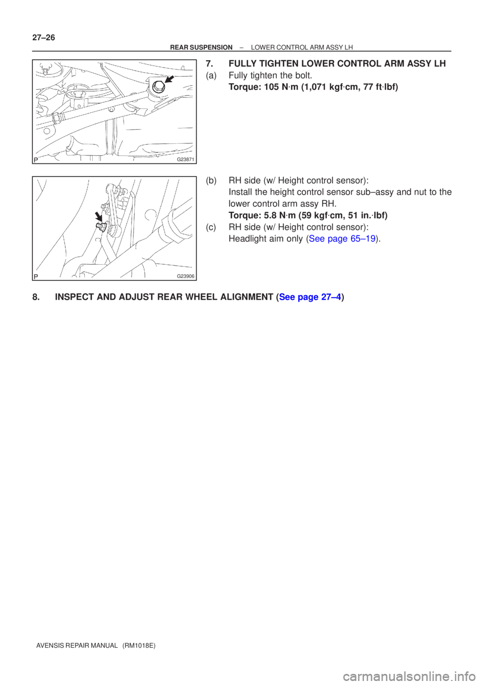
7. FULLY TIGHTEN LOWER CONTROL ARM ASSY LH
(a) Fully tighten the bolt. Torque: 105 N �m (1,071 kgf �cm, 77 ft �lbf)
(b) RH side (w/ Height control sensor): Install the height control sensor sub±assy and nut to the
lower control arm assy RH.
Torque: 5.8 N �m (59 kgf �cm, 51 in. �lbf)
(c) RH side (w/ Height control sensor): Headlight aim only (See page 65±19).
8.INSPECT AND ADJUST REAR WHEEL ALIGNMENT (See page 27±4)
Page 1250 of 1690

(c) Install the rear suspension arm assy No.1 LH with the 3
bolts.
Torque: 6")
G23868
G23867
G25772
G25771
27±12
± REAR SUSPENSIONREAR SHOCK ABSORBER WITH COIL SPRING
AVENSIS REPAIR MANUAL (RM1018E)
(c) Install the rear suspension arm assy No.1 LH with the 3
bolts.
Torque: 65 N�m (663 kgf�cm, 48 ft�lbf)
(d) Connect the parking brake cable assy No.3 with the 2
bolts.
Torque: 5.0 N�m (51 kgf�cm, 44 in.�lbf)
19. INSTALL REAR STABILIZER LINK ASSY LH
(a) Install the rear stabilizer link assy LH with the nut.
Torque: 44 N�m (449 kgf�cm, 32 ft�lbf)
HINT:
If the ball joint turns together with the nut, use a hexagon (5 mm)
wrench to hold the stud.
20. INSTALL REAR STABILIZER LINK ASSY RH
HINT:
Install the RH side by the same procedures as the LH side.
21. CONNECT SKID CONTROL SENSOR WIRE
(a) Install the wire bracket and bolt.
Torque: 5.0 N�m (51 kgf�cm, 44 in.�lbf)
(b) Connect the skid control sensor connector.
22. INSTALL REAR WHEEL
Torque: 103 N�m (1,050 kgf�cm, 76 ft�lbf)
23. STABILIZE SUSPENSION
(a) Bounce the vehicle up and down several times to stabilize the suspension.
Page 1251 of 1690
G23865
±
REAR SUSPENSION REAR SHOCK ABSORBER WITH COIL SPRING
27±13
AVENSIS REPAIR MANUAL (RM1018E)
24. FULLY TIGHTEN REAR SHOCK ABSORBER WITH
COIL SPRING
(a) Fully tighten the bolt and nut.
Torque: 160 N �m (1,632 kgf �cm, 118 ft �lbf)
NOTICE:
�When installing the bolt, hold the nut not to rotate.
�Be sure to empty the vehicle when fully tightening the
bolt and nut.
25.INSPECT AND ADJUST REAR WHEEL ALIGNMENT (See page 27±4)
26. CHECK ABS SPEED SENSOR SIGNAL
(a)ABD WITH EBD SYSTEM (See page 05±699)
(b)ABD WITH EBD & BA & TRC & VSC SYSTEM ( See page 05±756)
Page 1262 of 1690
G23875
G23874
G23865
G23880
27±22
± REAR SUSPENSIONREAR SUSPENSION ARM ASSY NO.1 LH
AVENSIS REPAIR MANUAL (RM1018E)
14. INSTALL REAR WHEEL
Torque: 103 N�m (1,050 kgf�cm, 76 ft�lbf)
15. STABILIZE SUSPENSION
(a) Bounce the vehicle up and down several times to stabilize the suspension.
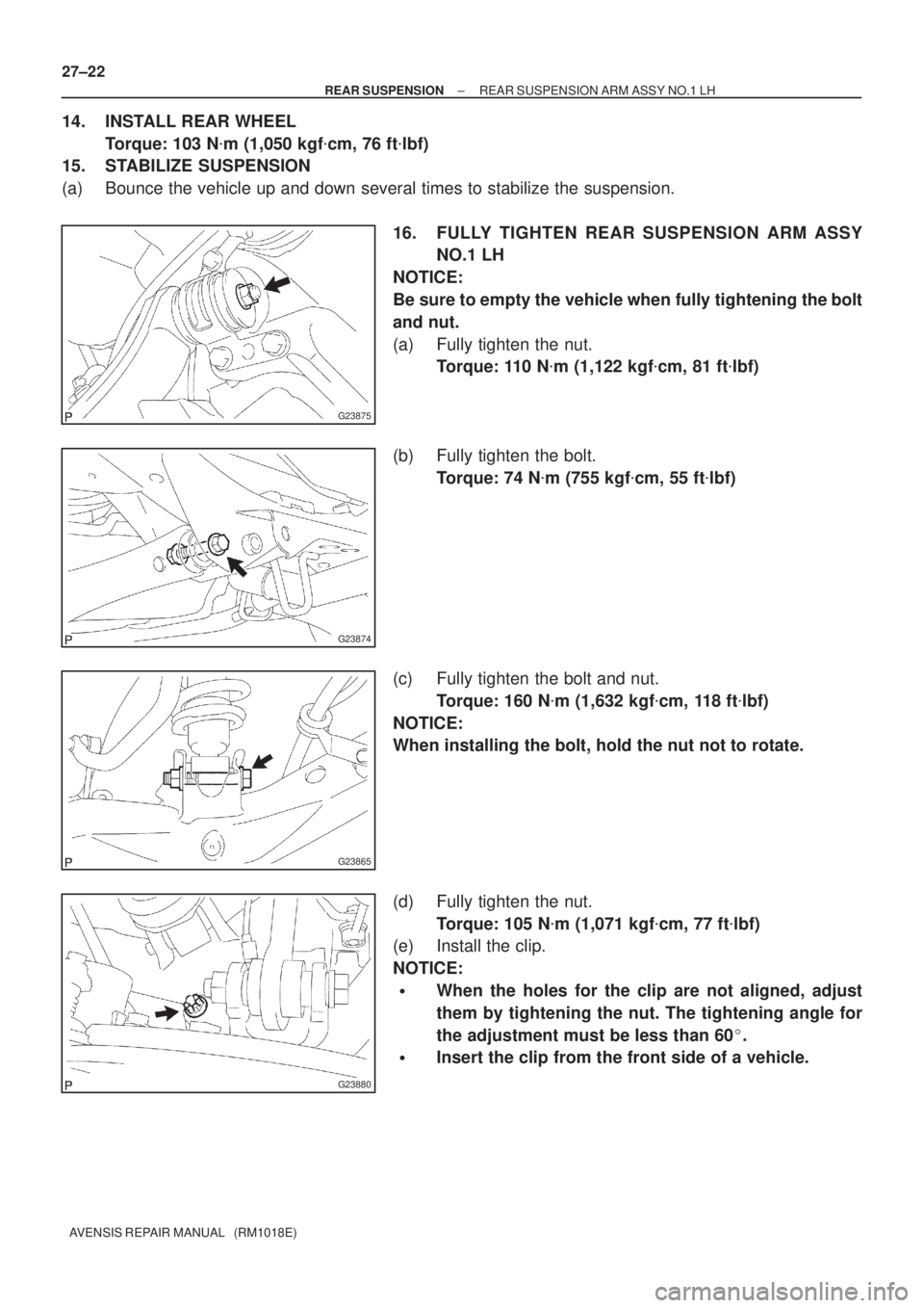
16. FULLY TIGHTEN REAR SUSPENSION ARM ASSY
NO.1 LH
NOTICE:
Be sure to empty the vehicle when fully tightening the bolt
and nut.
(a) Fully tighten the nut.
Torque: 110 N�m (1,122 kgf�cm, 81 ft�lbf)
(b) Fully tighten the bolt.
Torque: 74 N�m (755 kgf�cm, 55 ft�lbf)
(c) Fully tighten the bolt and nut.
Torque: 160 N�m (1,632 kgf�cm, 118 ft�lbf)
NOTICE:
When installing the bolt, hold the nut not to rotate.
(d) Fully tighten the nut.
Torque: 105 N�m (1,071 kgf�cm, 77 ft�lbf)
(e) Install the clip.
NOTICE:
�When the holes for the clip are not aligned, adjust
them by tightening the nut. The tightening angle for
the adjustment must be less than 60�.
�Insert the clip from the front side of a vehicle.
Page 1263 of 1690
G23881
������G25777
G23871
±
REAR SUSPENSION REAR SUSPENSION ARM ASSY NO.1 LH
27±23
AVENSIS REPAIR MANUAL (RM1018E)
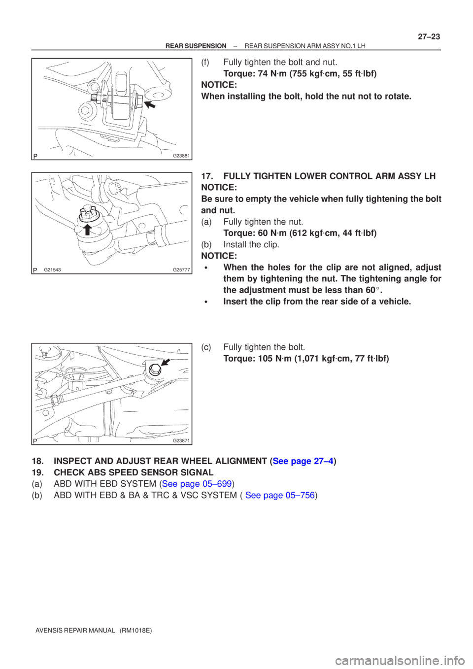
(f) Fully tighten the bolt and nut.
Torque: 74 N �m (755 kgf �cm, 55 ft �lbf)
NOTICE:
When installing the bolt, hold the nut not to rotate.
17. FULLY TIGHTEN LOWER CONTROL ARM ASSY LH
NOTICE:
Be sure to empty the vehicle when fully tightening the bolt
and nut.
(a) Fully tighten the nut. Torque: 60 N �m (612 kgf �cm, 44 ft �lbf)
(b) Install the clip.
NOTICE:
�When the holes for the clip are not aligned, adjust
them by tightening the nut. The tightening angle for
the adjustment must be less than 60 �.
�Insert the clip from the rear side of a vehicle.
(c) Fully tighten the bolt. Torque: 105 N �m (1,071 kgf �cm, 77 ft �lbf)
18.INSPECT AND ADJUST REAR WHEEL ALIGNMENT (See page 27±4)
19. CHECK ABS SPEED SENSOR SIGNAL
(a)ABD WITH EBD SYSTEM (See page 05±699)
(b)ABD WITH EBD & BA & TRC & VSC SYSTEM ( See page 05±756)
Page 1266 of 1690

G23877
G23886
Outward Inward
LongerShorterInward Outward
Front
Longer Shorter CAMBER ADJUSTING CAM ASSY
TIE ROD ADJUSTING TUBE
± REAR SUSPENSIONREAR WHEEL ALIGNMENT
27±5
AVENSIS REPAIR MANUAL (RM1018E)
(d) Loosen the camber adjusting cam assy set nut.
(e) Loosen the tie rod adjusting tube set nut.
(f) Adjust the camber and toe±in by turning the adjusting
cam and adjusting tube.
HINT:
Adjust the camber and toe±in to the center of the specified val-
ues as much as possible.
Toe±in:
(Normal package)
Toe±in
(total)A + B: 0���' � 6' (0.3� � 0.1�)
C ± D: 3.0 � 1.0 mm (0.12 � 0.04 in.)
(Rough road package)
Toe±in
(total)A + B: 0���' � 6' (0.3� � 0.1�)
C ± D: 3.0 � 1.0 mm (0.12 � 0.04 in.)
Camber:
(Normal package)
Camber
Right±left error±0���' � 20' (±0.9� � 0.3�)
30' (0.5�) or less
(Rough road package)
Camber
Right±left error±0���' � 20' (±0.5� � 0.3�)
30' (0.5�) or less
(g) Tighten the camber adjusting cam assy set nut.
Torque: 74 N�m (755 kgf�cm, 55 ft�lbf)
(h) Tighten the tie rod adjusting tube set nut.
Torque: 56 N�m (571 kgf�cm, 41 ft�lbf)
Page 1270 of 1690
G23878
Inner side
Stopper Ring
G23876
G25774
27±30
±
REAR SUSPENSION STABILIZER BAR REAR
AVENSIS REPAIR MANUAL (RM1018E)
5. INSTALL STABILIZER BAR REAR
(a) Install the 2 stabilizer bush rear to each stabilizer bar rear.
HINT:
Install the stabilizer bush rear to the outer side of the stopper
ring on the stabilizer bar.
(b) Install the stabilizer bar rear and 2 rear stabilizer bar bracket No.3 with 2 bolts and 2 nuts.
Torque: 35 N �m (357 kgf �cm, 26 ft �lbf)
6. INSTALL REAR STABILIZER LINK ASSY LH
(a) Install the rear stabilizer link assy LH with the 2 nuts. Torque: 44 N �m (449 kgf �cm, 32 ft �lbf)
HINT:
If the ball joint turns together with the nut, use a hexagon (5 mm)
wrench to hold the stud.
7. INSTALL REAR STABILIZER LINK ASSY RH
HINT:
Install the RH side by the same procedures as the LH side.
8.INSPECT AND ADJUST REAR WHEEL ALIGNMENT (See page 27±4)
Page 1272 of 1690
G21542
G21542
G23879
Matchmarks
27±28
±
REAR SUSPENSION UPPER CONTROL ARM ASSY
AVENSIS REPAIR MANUAL (RM1018E)
(b) Install the upper control arm assy, and temporarily tighten the bolt and nut.
4. INSTALL REAR WHEEL Torque: 103 N �m (1,050 kgf �cm, 76 ft �lbf)
5.STABILIZE SUSPENSION (See page 27±8)
6. FULLY TIGHTEN UPPER CONTROL ARM ASSY
NOTICE:
Be sure to empty the vehicle when fully tightening the bolt
and nut.
(a) Fully tighten the bolt and nut.Torque: 74 N �m (755 kgf �cm, 55 ft �lbf)
NOTICE:
When instaling the bolt, hold the nut not to rotate.
(b) Align the matchmarks, and fully tighten the nut. Torque: 74 N �m (755 kgf �cm, 55 ft �lbf)
7.INSPECT AND ADJUST REAR WHEEL ALIGNMENT (See page 27±4)

24. FULLY TIGHTEN REAR SHOCK ABSORBER WITH
COIL SPRING
(a) Fully tighten the bolt and nut.
Torqu")

5. INSTALL STABILIZER BAR REAR
(a) Install the 2 stabilizer bush rear to ea")

(b) Install the upper control arm assy, and temporarily tighten the bolt and nut.
4.")