Page 724 of 1690
110UC±01
A79148
SST
A79143
SST
11±78
±
FUEL COMMON RAIL ASSY(1CD±FTV)
AVENSIS REPAIR MANUAL (RM1018E)
REPLACEMENT
1.DRAIN ENGINE COOLANT(See page 16±44)
2. REMOVE RADIATOR SUPPORT OPENING COVER
3. REMOVE ENGINE COVER NO.1
(a) Remove the 5 nuts and the engine cover.
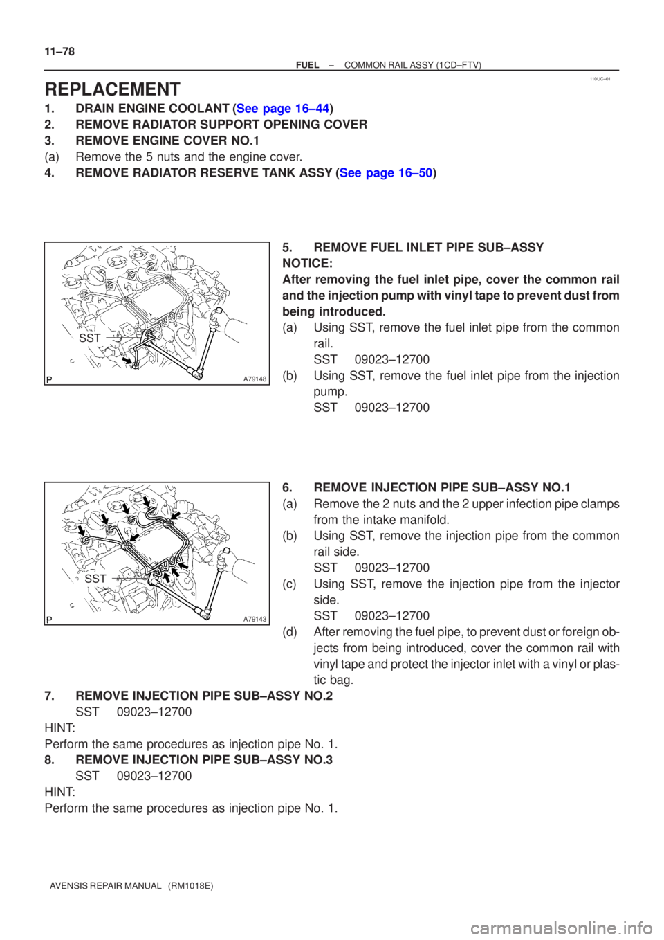
4.REMOVE RADIATOR RESERVE TANK ASSY(See page 16±50) 5. REMOVE FUEL INLET PIPE SUB±ASSY
NOTICE:
After removing the fuel inlet pipe, cover the common rail
and the injection pump with vinyl tape to prevent dust from
being introduced.
(a) Using SST, remove the fuel inlet pipe from the commonrail.
SST 09023±12700
(b) Using SST, remove the fuel inlet pipe from the injection pump.
SST 09023±12700
6. REMOVE INJECTION PIPE SUB±ASSY NO.1
(a) Remove the 2 nuts and the 2 upper infection pipe clamps from the intake manifold.
(b) Using SST, remove the injection pipe from the common
rail side.
SST 09023±12700
(c) Using SST, remove the injection pipe from the injector side.
SST 09023±12700
(d) After removing the fuel pipe, to prevent dust or foreign ob- jects from being introduced, cover the common rail with
vinyl tape and protect the injector inlet with a vinyl or plas-
tic bag.
7. REMOVE INJECTION PIPE SUB±ASSY NO.2 SST 09023±12700
HINT:
Perform the same procedures as injection pipe No. 1.
8. REMOVE INJECTION PIPE SUB±ASSY NO.3 SST 09023±12700
HINT:
Perform the same procedures as injection pipe No. 1.
Page 727 of 1690
A79149
30 cm
(11.81 in.)
SST
±
FUEL COMMON RAIL ASSY(1CD±FTV)
11±81
AVENSIS REPAIR MANUAL (RM1018E)
19.INSTALL FUEL INLET PIPE SUB±ASSY
NOTICE:
�In case of having the common rail replaced, must re-
place fuel inlet pipe, too.
�When assembling the pipe, perform the operation
with the engine cold under room temperature.
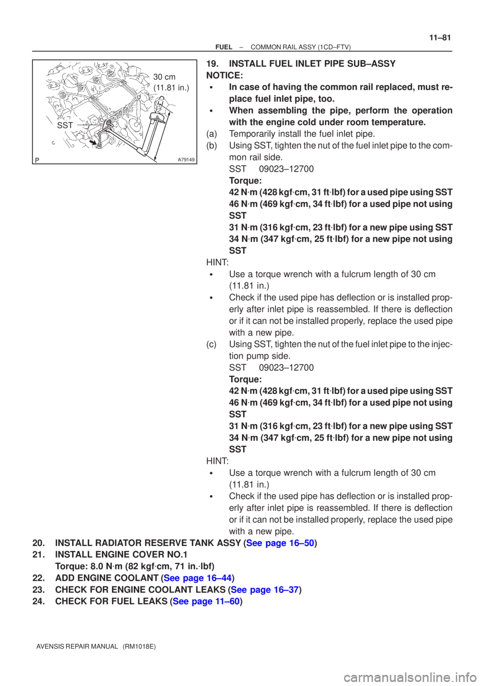
(a)Temporarily install the fuel inlet pipe.
(b)Using SST, tighten the nut of the fuel inlet pipe to the com-
mon rail side.
SST09023±12700
Torque:
42 N�m (428 kgf �cm, 31 ft �lbf) for a used pipe using SST
46 N �m (469 kgf �cm, 34 ft �lbf) for a used pipe not using
SST
31 N �m (316 kgf �cm, 23 ft �lbf) for a new pipe using SST
34 N �m (347 kgf �cm, 25 ft �lbf) for a new pipe not using
SST
HINT:
�Use a torque wrench with a fulcrum length of 30 cm
(11.81 in.)
�Check if the used pipe has deflection or is installed prop-
erly after inlet pipe is reassembled. If there is deflection
or if it can not be installed properly, replace the used pipe
with a new pipe.
(c)Using SST, tighten the nut of the fuel inlet pipe to the injec-
tion pump side.
SST09023±12700
Torque:
42 N�m (428 kgf �cm, 31 ft �lbf) for a used pipe using SST
46 N �m (469 kgf �cm, 34 ft �lbf) for a used pipe not using
SST
31 N �m (316 kgf �cm, 23 ft �lbf) for a new pipe using SST
34 N �m (347 kgf �cm, 25 ft �lbf) for a new pipe not using
SST
HINT:
�Use a torque wrench with a fulcrum length of 30 cm
(11.81 in.)
�Check if the used pipe has deflection or is installed prop-
erly after inlet pipe is reassembled. If there is deflection
or if it can not be installed properly, replace the used pipe
with a new pipe.
20.INSTALL RADIATOR RESERVE TANK ASSY(See page 16±50)
21. INSTALL ENGINE COVER NO.1 Torque: 8.0 N �m (82 kgf �cm, 71 in. �lbf)
22.ADD ENGINE COOLANT(See page 16±44)
23.CHECK FOR ENGINE COOLANT LEAKS(See page 16±37)
24.CHECK FOR FUEL LEAKS(See page 11±60)
Page 810 of 1690
110UA±01
A15950
±
FUEL INJECTION OR SUPPLY PUMP ASSY(1CD±FTV)
11±69
AVENSIS REPAIR MANUAL (RM1018E)
REPLACEMENT
1.REMOVE FRONT WHEEL RH
2.DRAIN ENGINE COOLANT(See page 16±44)
3.REMOVE ENGINE UNDER COVER SUB±ASSY NO.1
4.REMOVE ENGINE UNDER COVER RH
5.REMOVE RADIATOR SUPPORT OPENING COVER
6.REMOVE ENGINE ROOM COVER SIDE
7.REMOVE AIR CLEANER ASSY (See page 11±60)
8.REMOVE ENGINE COVER NO.1
(a)Remove the 5 nuts and the engine cover.
9.REMOVE RADIATOR RESERVE TANK ASSY(See page 16±50)
10.DISCONNECT RADIATOR HOSE OUTLET
(a)Disconnect the radiator hose outlet from the water inlet.
11.REMOVE V (COOLER COMPRESSOR TO CRANKSHAFT PULLEY) BELT NO.1
(See page 14±269)
12.REMOVE GENERATOR V BELT (See page 14±269)
13.REMOVE INJECTOR DRIVER
(a)Remove the 2 nuts which are used to secure the injector driver.
(b)Disconnect the injector driver connector and the harness clamp.
(c)Remove the injector driver.
14.REMOVE ENGINE MOUNTING INSULATOR SUB±ASSY RH(See page 14±307)
15.REMOVE CRANKSHAFT PULLEY(See page 14±307)
SST09213±54015 (90105±08076), 09330±00021, 09950±50013 (0995\
1±05010, 09952±05010, 09953±05020, 09954±05031)
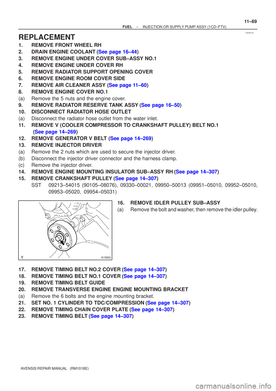
16.REMOVE IDLER PULLEY SUB±ASSY
(a)Remove the bolt and washer, then remove the idler pulley.
17.REMOVE TIMING BELT NO.2 COVER(See page 14±307)
18.REMOVE TIMING BELT NO.1 COVER(See page 14±307)
19. REMOVE TIMING BELT GUIDE
20. REMOVE TRANSVERSE ENGINE ENGINE MOUNTING BRACKET
(a) Remove the 6 bolts and the engine mounting bracket.
21.SET NO. 1 CYLINDER TO TDC/COMPRESSION(See page 14±307)
22.REMOVE TIMING CHAIN COVER PLATE(See page 14±307)
23.REMOVE TIMING BELT(See page 14±307)
Page 816 of 1690
±
FUEL INJECTION OR SUPPLY PUMP ASSY (1CD±FTV)
11±75
AVENSIS REPAIR MANUAL (RM1018E)
52.INSTALL TIMING BELT GUIDE(See page 14±307)
53.INSTALL TIMING BELT NO.1 COVER(See page 14±307)
54.INSTALL TIMING BELT NO.2 COVER(See page 14±307)
55. INSTALL IDLER PULLEY SUB±ASSY
Torque: 40 N �m (408 kgf �cm, 30 ft �lbf)
56.INSTALL CRANKSHAFT PULLEY(See page 14±307) SST 09213±54015 (90105±08076), 09330±00021
57.INSTALL ENGINE MOUNTING INSULATOR SUB±ASSY RH(See page 14±307)
58. INSTALL INJECTOR DRIVER Torque: 5.0 N �m (51 kgf �cm, 44 in. �lbf)
59. ADJUST V (COOLER COMPRESSOR TO CRANKSHAFT PULLEY) BELT NO.1 (See page 14±269)
60.INSTALL RADIATOR RESERVE TANK ASSY(See page 16±50)
61. INSTALL ENGINE COVER NO.1 Torque: 8.0 N �m (82 kgf �cm, 71 in. �lbf)
62.INSTALL AIR CLEANER ASSY (See page 11±60)
63. INSTALL FRONT WHEEL RH
Torque: 103 N �m (1,050 kgf �cm, 76 ft �lbf)
64.ADD ENGINE COOLANT(See page 16±44)
65.CHECK FOR ENGINE COOLANT LEAKS(See page 16±37)
66.CHECK FOR FUEL LEAKS(See page 11±60)
Page 837 of 1690
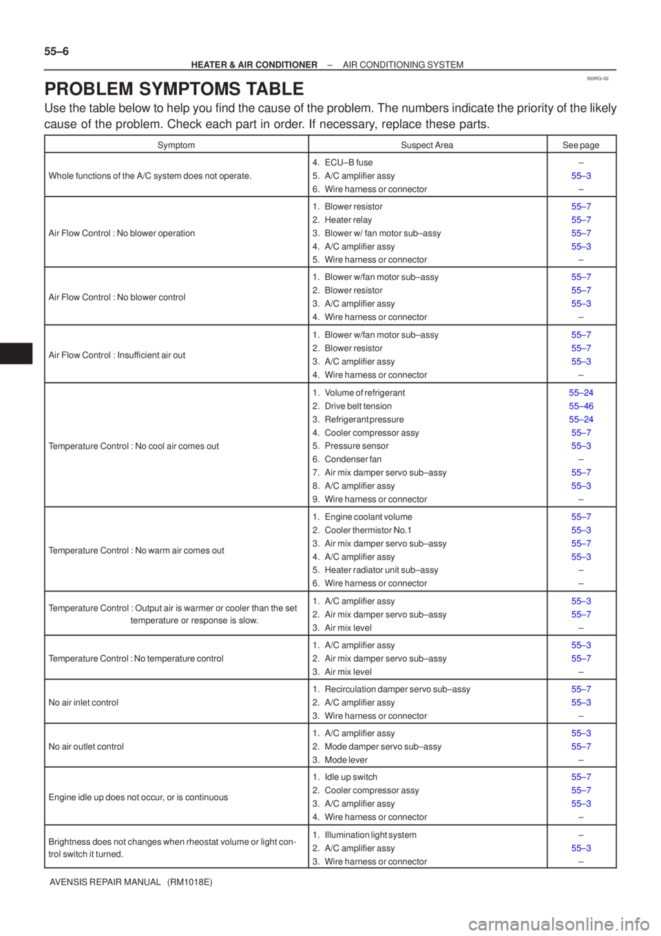
550RQ±02
55±6
±
HEATER & AIR CONDITIONER AIR CONDITIONING SYSTEM
AVENSIS REPAIR MANUAL (RM1018E)
PROBLEM SYMPTOMS TABLE
Use the table below to help you find the cause of the problem. The numbers \
indicate the priority of the likely
cause of the problem. Check each part in order. If necessary, replace these parts.
SymptomSuspect AreaSee page
Whole functions of the A/C system does not operate.
4. ECU±B fuse
5. A/C amplifier assy
6. Wire harness or connector±
55±3 ±
Air Flow Control : No blower operation
1. Blower resistor
2. Heater relay
3. Blower w/ fan motor sub±assy
4. A/C amplifier assy
5. Wire harness or connector55±7
55±7
55±7
55±3±
Air Flow Control : No blower control
1. Blower w/fan motor sub±assy
2. Blower resistor
3. A/C amplifier assy
4. Wire harness or connector55±7
55±7
55±3
±
Air Flow Control : Insufficient air out
1. Blower w/fan motor sub±assy
2. Blower resistor
3. A/C amplifier assy
4. Wire harness or connector55±7
55±7
55±3±
Temperature Control : No cool air comes out
1. Volume of refrigerant
2. Drive belt tension
3. Refrigerant pressure
4. Cooler compressor assy
5. Pressure sensor
6. Condenser fan
7. Air mix damper servo sub±assy
8. A/C amplifier assy
9. Wire harness or connector55±24
55±46
55±2455±7
55±3 ±
55±7
55±3 ±
Temperature Control : No warm air comes out
1. Engine coolant volume
2. Cooler thermistor No.1
3. Air mix damper servo sub±assy
4. A/C amplifier assy
5. Heater radiator unit sub±assy
6. Wire harness or connector55±7
55±3
55±7
55±3±
±
Temperature Control : Output air is warmer or cooler than the set
temperature or response is slow.1. A/C amplifier assy
2. Air mix damper servo sub±assy
3. Air mix level55±3
55±7
±
Temperature Control : No temperature control
1. A/C amplifier assy
2. Air mix damper servo sub±assy
3. Air mix level55±3
55±7±
No air inlet control
1. Recirculation damper servo sub±assy
2. A/C amplifier assy
3. Wire harness or connector55±7
55±3±
No air outlet control
1. A/C amplifier assy
2. Mode damper servo sub±assy
3. Mode lever55±3
55±7±
Engine idle up does not occur, or is continuous
1. Idle up switch
2. Cooler compressor assy
3. A/C amplifier assy
4. Wire harness or connector55±7
55±7
55±3±
Brightness does not changes when rheostat volume or light con-
trol switch it turned.1. Illumination light system
2. A/C amplifier assy
3. Wire harness or connector±
55±3 ±
Page 856 of 1690
550ZE±01
±
HEATER & AIR CONDITIONER ELECTRICAL TYPE POWER HEATER SYSTEM
55±13
AVENSIS REPAIR MANUAL (RM1018E)
ELECTRICAL TYPE POWER HEATER SYSTEM
PROBLEM SYMPTOMS TABLE
Use the table below to help you find the cause of the problem. The numbers \
indicate the priority of the likely
cause of the problem. Check each part in order. If necessary, replace these parts.
SymptomSuspect AreaSee page
PTC heater does not operate, when perform in these conditions:
�Engine coolant temp.: 70 �C (158 �F) or below
� Engine speed: 650 rpm or above
� Temperature control selector: MAX. HOT
� Ambient temperature: Below 10 �C (50 �F)
1. HTR1 Fuse
2. HTR2 Fuse
3. HTR1 relay
4. HTR2 relay
5. PTC heater
6. ECM
7. Wire harness±
±
±
±
55±14
±
±
Page 858 of 1690
550ZE±01
±
HEATER & AIR CONDITIONER ELECTRICAL TYPE POWER HEATER SYSTEM
55±13
AVENSIS REPAIR MANUAL (RM1018E)
ELECTRICAL TYPE POWER HEATER SYSTEM
PROBLEM SYMPTOMS TABLE
Use the table below to help you find the cause of the problem. The numbers \
indicate the priority of the likely
cause of the problem. Check each part in order. If necessary, replace these parts.
SymptomSuspect AreaSee page
PTC heater does not operate, when perform in these conditions:
�Engine coolant temp.: 70 �C (158 �F) or below
� Engine speed: 650 rpm or above
� Temperature control selector: MAX. HOT
� Ambient temperature: Below 10 �C (50 �F)
1. HTR1 Fuse
2. HTR2 Fuse
3. HTR1 relay
4. HTR2 relay
5. PTC heater
6. ECM
7. Wire harness±
±
±
±
55±14
±
±
Page 861 of 1690
I35349
I35350
I35350
I35349
±
HEATER & AIR CONDITIONER HEATER ASSY
55±101
AVENSIS REPAIR MANUAL (RM1018E)
6. REMOVE HEATER ASSY
(a) Using pliers, grip the claws of the clip and slide the clip to
disconnect the heater fuel hose.
HINT:
Prepare a support plate and waste to catch the leaked fuel.
(b) Disconnect the connector.
(c) Remove the 2 bolts and the heater assy.
7. INSTALL HEATER ASSY
(a) Install the heater assy with the 2 bolts. Torque: 7.5 N �m (76 kgf �cm, 66 in. �lbf)
(b) Connect the connector.
(c) Install the heater fuel hose.
HINT:
Prepare a support plate and waste to catch the leaked fuel.
8.INSTALL FUEL FILTER ASSY (See page 11±82)
9.INSTALL AIR CLEANER ASSY (See page 11±82)
10.ADD ENGINE COOLANT (See page 16±44)
11.CHECK FOR ENGINE COOLANT LEAKS (See page 16±37)
12.CHECK FUEL LEAK (See page 11±56)