2002 NISSAN TERRANO check engine
[x] Cancel search: check enginePage 114 of 1767
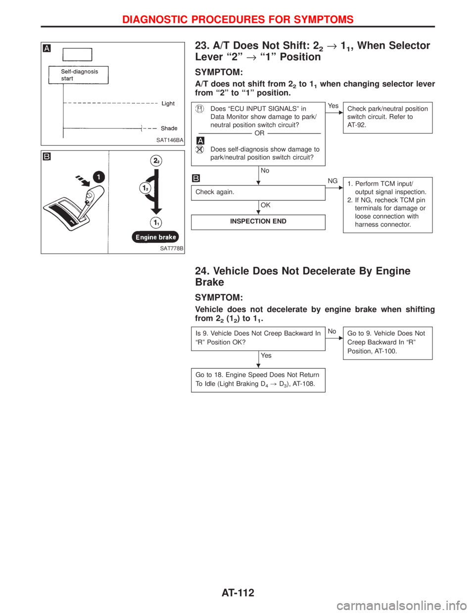
23. A/T Does Not Shift: 22®11, When Selector
Lever ª2º®ª1º Position
SYMPTOM:
A/T does not shift from 22to 11when changing selector lever
from ª2º to ª1º position.
Does ªECU INPUT SIGNALSº in
Data Monitor show damage to park/
neutral position switch circuit?
-----------------------------------------------------------------------------------------------------------------------OR -----------------------------------------------------------------------------------------------------------------------
Does self-diagnosis show damage to
park/neutral position switch circuit?
No
EYe s
Check park/neutral position
switch circuit. Refer to
AT-92.
Check again.
OK
ENG
1. Perform TCM input/
output signal inspection.
2. If NG, recheck TCM pin
terminals for damage or
loose connection with
harness connector.
INSPECTION END
24. Vehicle Does Not Decelerate By Engine
Brake
SYMPTOM:
Vehicle does not decelerate by engine brake when shifting
from 2
2(12)to11.
Is 9. Vehicle Does Not Creep Backward In
ªRº Position OK?
Ye s
ENo
Go to 9. Vehicle Does Not
Creep Backward In ªRº
Position, AT-100.
Go to 18. Engine Speed Does Not Return
To Idle (Light Braking D
4,D3), AT-108.
SAT146BA
SAT778B
H
H
H
DIAGNOSTIC PROCEDURES FOR SYMPTOMS
AT-112
Page 116 of 1767
Revolution Sensor Replacement
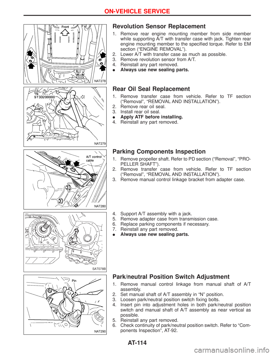
1. Remove rear engine mounting member from side member
while supporting A/T with transfer case with jack. Tighten rear
engine mounting member to the specified torque. Refer to EM
section (ªENGINE REMOVALº).
2. Lower A/T with transfer case as much as possible.
3. Remove revolution sensor from A/T.
4. Reinstall any part removed.
IAlways use new sealing parts.
Rear Oil Seal Replacement
1. Remove transfer case from vehicle. Refer to TF section
(ªRemovalº, ªREMOVAL AND INSTALLATIONº).
2. Remove rear oil seal.
3. Install rear oil seal.
IApply ATF before installing.
4. Reinstall any part removed.
Parking Components Inspection
1. Remove propeller shaft. Refer to PD section (ªRemovalº, ªPRO-
PELLER SHAFTº).
2. Remove transfer case from vehicle. Refer to TF section
(ªRemovalº, ªREMOVAL AND INSTALLATIONº).
3. Remove manual control linkage bracket from adapter case.
4. Support A/T assembly with a jack.
5. Remove adapter case from transmission case.
6. Replace parking components if necessary.
7. Reinstall any part removed.
IAlways use new sealing parts.
Park/neutral Position Switch Adjustment
1. Remove manual control linkage from manual shaft of A/T
assembly.
2. Set manual shaft of A/T assembly in ªNº position.
3. Loosen park/neutral position switch fixing bolts.
4. Insert pin into adjustment holes in both park/neutral position
switch and manual shaft of A/T assembly as near vertical as
possible.
5. Reinstall any part removed.
6. Check continuity of park/neutral position switch. Refer to ªCom-
ponents Inspectionº, AT-92.
NAT278
NAT279
NAT280
SAT078B
NAT290
ON-VEHICLE SERVICE
AT-114
Page 119 of 1767
10. Remove starter motor.
11. Remove gusset and rear plate cover securing engine to A/T
assembly.
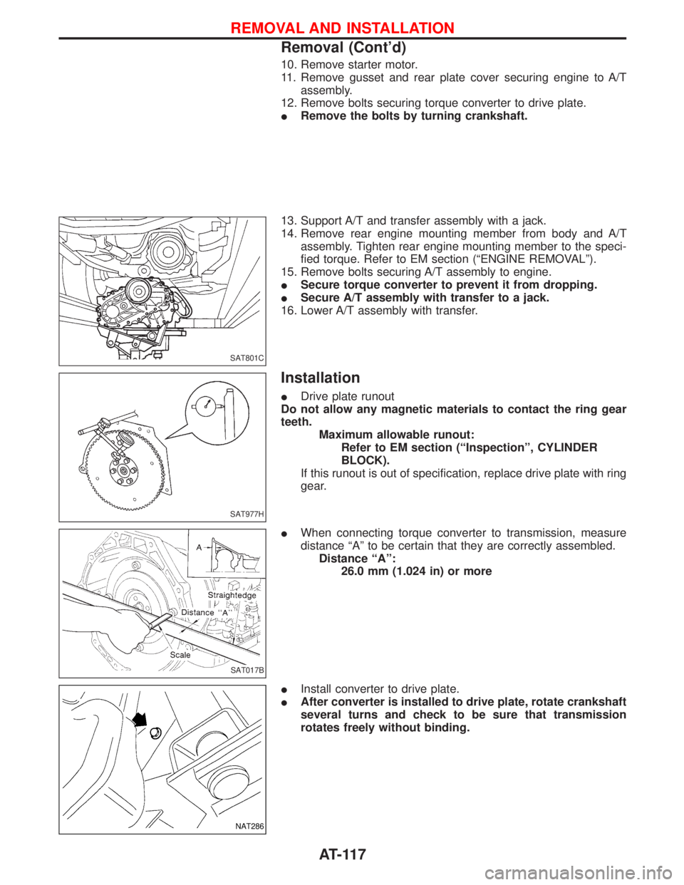
12. Remove bolts securing torque converter to drive plate.
IRemove the bolts by turning crankshaft.
13. Support A/T and transfer assembly with a jack.
14. Remove rear engine mounting member from body and A/T
assembly. Tighten rear engine mounting member to the speci-
fied torque. Refer to EM section (ªENGINE REMOVALº).
15. Remove bolts securing A/T assembly to engine.
ISecure torque converter to prevent it from dropping.
ISecure A/T assembly with transfer to a jack.
16. Lower A/T assembly with transfer.
Installation
IDrive plate runout
Do not allow any magnetic materials to contact the ring gear
teeth.
Maximum allowable runout:
Refer to EM section (ªInspectionº, CYLINDER
BLOCK).
If this runout is out of specification, replace drive plate with ring
gear.
IWhen connecting torque converter to transmission, measure
distance ªAº to be certain that they are correctly assembled.
Distance ªAº:
26.0 mm (1.024 in) or more
IInstall converter to drive plate.
IAfter converter is installed to drive plate, rotate crankshaft
several turns and check to be sure that transmission
rotates freely without binding.
SAT801C
SAT977H
SAT017B
NAT286
REMOVAL AND INSTALLATION
Removal (Cont'd)
AT-117
Page 120 of 1767
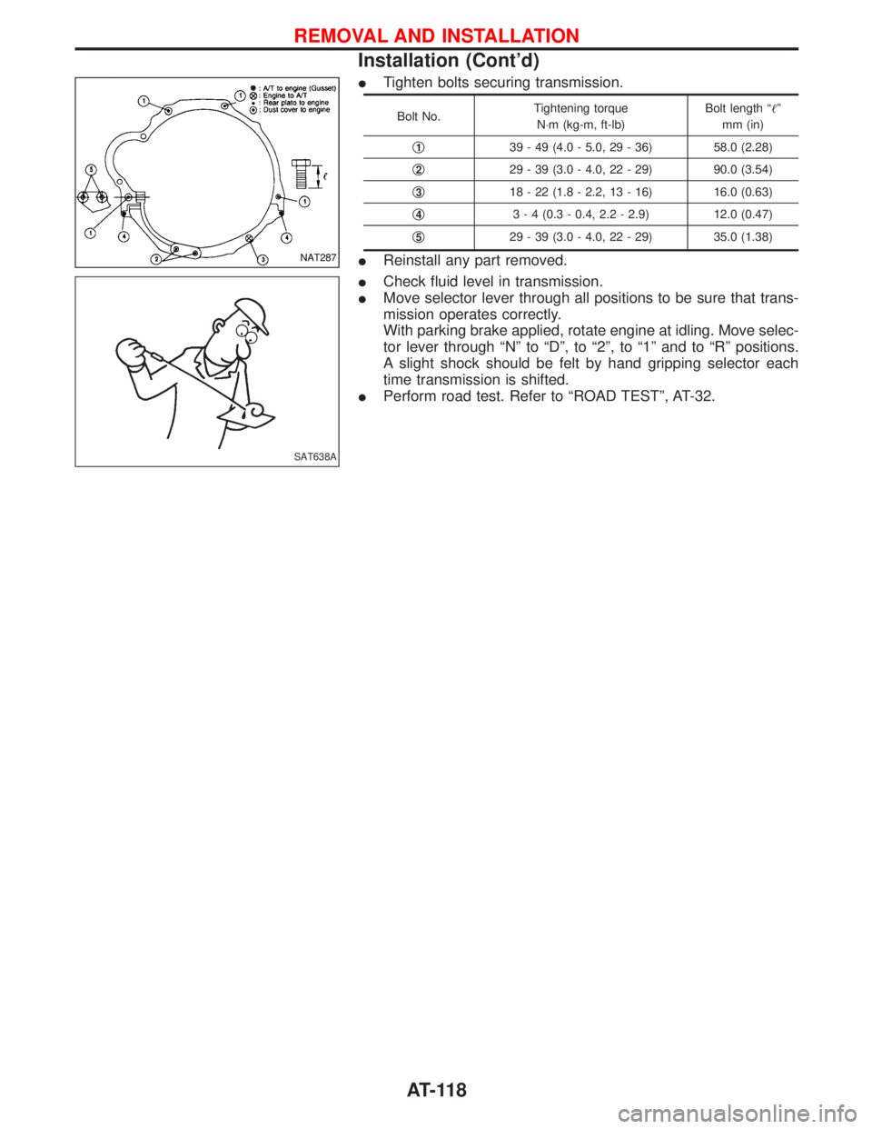
ITighten bolts securing transmission.
Bolt No.Tightening torque
N×m (kg-m, ft-lb)Bolt length ªº
mm (in)
q
139 - 49 (4.0 - 5.0, 29 - 36) 58.0 (2.28)
q
229 - 39 (3.0 - 4.0, 22 - 29) 90.0 (3.54)
q
318 - 22 (1.8 - 2.2, 13 - 16) 16.0 (0.63)
q
43 - 4 (0.3 - 0.4, 2.2 - 2.9) 12.0 (0.47)
q
529 - 39 (3.0 - 4.0, 22 - 29) 35.0 (1.38)
IReinstall any part removed.
ICheck fluid level in transmission.
IMove selector lever through all positions to be sure that trans-
mission operates correctly.
With parking brake applied, rotate engine at idling. Move selec-
tor lever through ªNº to ªDº, to ª2º, to ª1º and to ªRº positions.
A slight shock should be felt by hand gripping selector each
time transmission is shifted.
IPerform road test. Refer to ªROAD TESTº, AT-32.NAT287
SAT638A
REMOVAL AND INSTALLATION
Installation (Cont'd)
AT-118
Page 126 of 1767
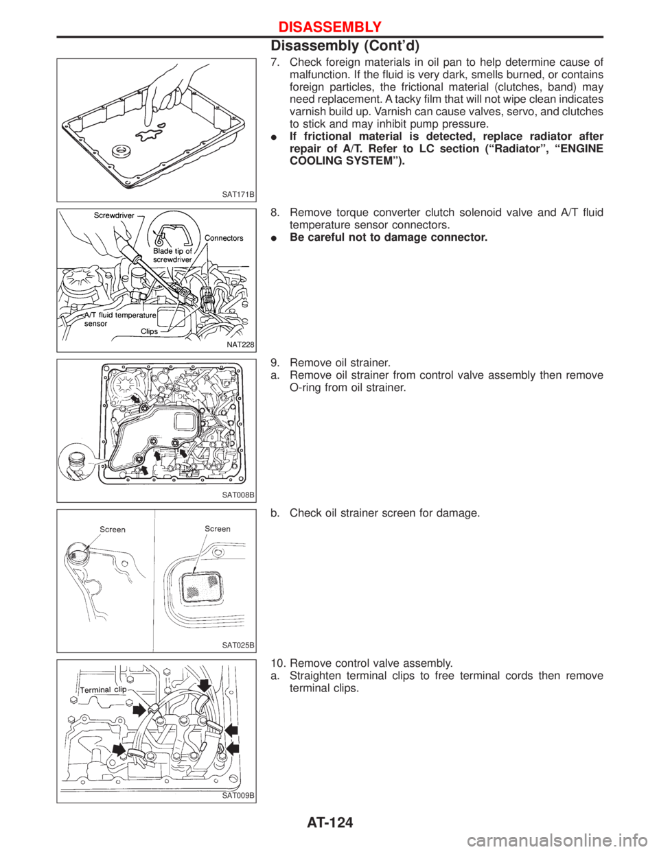
7. Check foreign materials in oil pan to help determine cause of
malfunction. If the fluid is very dark, smells burned, or contains
foreign particles, the frictional material (clutches, band) may
need replacement. A tacky film that will not wipe clean indicates
varnish build up. Varnish can cause valves, servo, and clutches
to stick and may inhibit pump pressure.
IIf frictional material is detected, replace radiator after
repair of A/T. Refer to LC section (ªRadiatorº, ªENGINE
COOLING SYSTEMº).
8. Remove torque converter clutch solenoid valve and A/T fluid
temperature sensor connectors.
IBe careful not to damage connector.
9. Remove oil strainer.
a. Remove oil strainer from control valve assembly then remove
O-ring from oil strainer.
b. Check oil strainer screen for damage.
10. Remove control valve assembly.
a. Straighten terminal clips to free terminal cords then remove
terminal clips.
SAT171B
NAT228
SAT008B
SAT025B
SAT009B
DISASSEMBLY
Disassembly (Cont'd)
AT-124
Page 203 of 1767
BRAKE SYSTEM
SECTION
BR
CONTENTS
PRECAUTIONS AND PREPARATION............................3
Supplement Restraint System (SRS)²AIR BAG²
and²SEAT BELT PRE-TENSIONER².........................3
Precautions ..................................................................3
Preparation ..................................................................4
CHECK AND ADJUSTMENT..........................................5
Checking Brake Fluid Level.........................................5
Checking Brake Line ...................................................5
Changing Brake Fluid ..................................................5
Brake Burnishing Procedure........................................5
BRAKE HYDRAULIC LINE.............................................6
Bleeding Brake System ...............................................8
Removal .......................................................................9
Inspection.....................................................................9
Installation ....................................................................9
LOAD SENSING VALVE...............................................10
Removal and Installation ...........................................10
Removal ..................................................................... 11
Installation .................................................................. 11
Inspection and Adjustment ........................................12
BRAKE PEDAL AND BRACKET..................................14
Removal and Installation ...........................................14
Inspection...................................................................15
Adjustment .................................................................15
MASTER CYLINDER.....................................................16
Removal .....................................................................16
Installation ..................................................................16
BRAKE BOOSTER........................................................17
Removal and Installation ...........................................17
Inspection...................................................................17
Installation ..................................................................18
VACUUM HOSE.............................................................19
Removal and Installation ...........................................19
Inspection...................................................................21
VACUUM PUMP (TD27Ti engine model)....................23
Removal and Installation ...........................................23
Inspection...................................................................23VACUUM PUMP (ZD30DDTi engine model)...............25
Removal and Installation ...........................................25
FRONT DISC BRAKE...................................................26
Pad Replacement ......................................................26
Removal .....................................................................27
Disassembly...............................................................27
Inspection...................................................................27
Assembly ...................................................................28
Inspection...................................................................28
Installation ..................................................................30
REAR DRUM BRAKE...................................................31
Removal .....................................................................32
Shoe Replacement ....................................................33
Inspection...................................................................33
Installation ..................................................................33
PARKING BRAKE CONTROL......................................35
Removal and Installation ...........................................35
Inspection...................................................................35
Adjustment .................................................................35
ANTI-LOCK BRAKE SYSTEM......................................37
Purpose......................................................................37
Operation ...................................................................37
ABS Hydraulic Circuit ................................................37
System Description ....................................................38
Removal and Installation ...........................................42
TROUBLE DIAGNOSES...............................................47
How to Perform Trouble Diagnoses for Quick
and Accurate Repair ..................................................47
Component Parts and Harness Connector
Location .....................................................................48
Circuit Diagram for Quick Pinpoint Check.................49
Wiring Diagram - ABS - .............................................50
CONSULT-II ...............................................................58
CONSULT-II Inspection Procedure............................59
Preliminary Check......................................................65
Ground Circuit Check ................................................66
Diagnostic Procedure 1 (Not self-diagnostic item) ....67
Page 207 of 1767
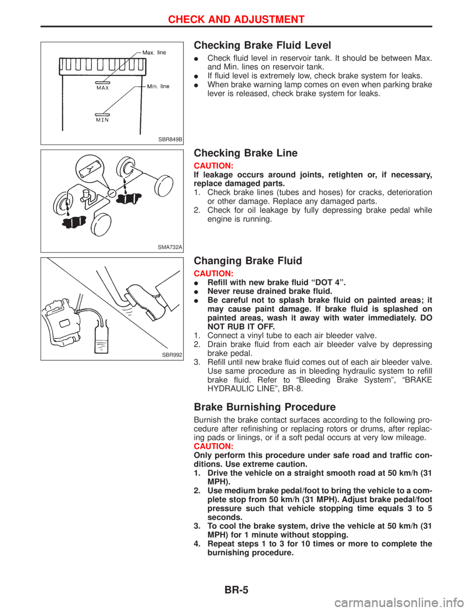
Checking Brake Fluid Level
ICheck fluid level in reservoir tank. It should be between Max.
and Min. lines on reservoir tank.
IIf fluid level is extremely low, check brake system for leaks.
IWhen brake warning lamp comes on even when parking brake
lever is released, check brake system for leaks.
Checking Brake Line
CAUTION:
If leakage occurs around joints, retighten or, if necessary,
replace damaged parts.
1. Check brake lines (tubes and hoses) for cracks, deterioration
or other damage. Replace any damaged parts.
2. Check for oil leakage by fully depressing brake pedal while
engine is running.
Changing Brake Fluid
CAUTION:
IRefill with new brake fluid ªDOT 4º.
INever reuse drained brake fluid.
IBe careful not to splash brake fluid on painted areas; it
may cause paint damage. If brake fluid is splashed on
painted areas, wash it away with water immediately. DO
NOT RUB IT OFF.
1. Connect a vinyl tube to each air bleeder valve.
2. Drain brake fluid from each air bleeder valve by depressing
brake pedal.
3. Refill until new brake fluid comes out of each air bleeder valve.
Use same procedure as in bleeding hydraulic system to refill
brake fluid. Refer to ªBleeding Brake Systemº, ªBRAKE
HYDRAULIC LINEº, BR-8.
Brake Burnishing Procedure
Burnish the brake contact surfaces according to the following pro-
cedure after refinishing or replacing rotors or drums, after replac-
ing pads or linings, or if a soft pedal occurs at very low mileage.
CAUTION:
Only perform this procedure under safe road and traffic con-
ditions. Use extreme caution.
1. Drive the vehicle on a straight smooth road at 50 km/h (31
MPH).
2. Use medium brake pedal/foot to bring the vehicle to a com-
plete stop from 50 km/h (31 MPH). Adjust brake pedal/foot
pressure such that vehicle stopping time equals 3 to 5
seconds.
3. To cool the brake system, drive the vehicle at 50 km/h (31
MPH) for 1 minute without stopping.
4. Repeat steps 1 to 3 for 10 times or more to complete the
burnishing procedure.
SBR849B
SMA732A
SBR992
CHECK AND ADJUSTMENT
BR-5
Page 215 of 1767
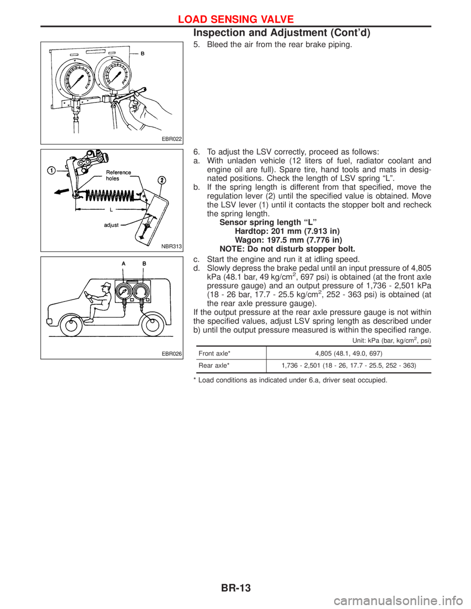
5. Bleed the air from the rear brake piping.
6. To adjust the LSV correctly, proceed as follows:
a. With unladen vehicle (12 liters of fuel, radiator coolant and
engine oil are full). Spare tire, hand tools and mats in desig-
nated positions. Check the length of LSV spring ªLº.
b. If the spring length is different from that specified, move the
regulation lever (2) until the specified value is obtained. Move
the LSV lever (1) until it contacts the stopper bolt and recheck
the spring length.
Sensor spring length ªLº
Hardtop: 201 mm (7.913 in)
Wagon: 197.5 mm (7.776 in)
NOTE: Do not disturb stopper bolt.
c. Start the engine and run it at idling speed.
d. Slowly depress the brake pedal until an input pressure of 4,805
kPa (48.1 bar, 49 kg/cm
2, 697 psi) is obtained (at the front axle
pressure gauge) and an output pressure of 1,736 - 2,501 kPa
(18 - 26 bar, 17.7 - 25.5 kg/cm
2, 252 - 363 psi) is obtained (at
the rear axle pressure gauge).
If the output pressure at the rear axle pressure gauge is not within
the specified values, adjust LSV spring length as described under
b) until the output pressure measured is within the specified range.
Unit: kPa (bar, kg/cm2, psi)
Front axle* 4,805 (48.1, 49.0, 697)
Rear axle* 1,736 - 2,501 (18 - 26, 17.7 - 25.5, 252 - 363)
* Load conditions as indicated under 6.a, driver seat occupied.
EBR022
NBR313
EBR026
LOAD SENSING VALVE
Inspection and Adjustment (Cont'd)
BR-13