Page 32 of 1767
Line Pressure Test
LINE PRESSURE TEST PORTS
ILocation of line pressure test ports.
IAlways replace line pressure plugs as they are self-
sealing bolts.
LINE PRESSURE TEST PROCEDURE
1. Check A/T and engine fluid levels. If necessary, add fluid.
2. Drive vehicle for approx. 10 minutes or until engine oil and ATF
reach operating temperature.
ATF operating temperature:
50 - 80ÉC (122 - 176ÉF)
3. Install pressure gauge to corresponding line pressure port.
SAT209GA
SAT647B
SAT518GB
SAT519GA
TROUBLE DIAGNOSIS Ð Basic Inspection
AT-30
Page 34 of 1767
Road Test
DESCRIPTION
IThe purpose of the test is to determine overall performance of
A/T and analyze causes of problems.
IThe road test consists of the following three parts:
1. Check before engine is started
2. Check at idle
3. Cruise test
IBefore road test, familiarize yourself with all test procedures
and items to check.
IConduct tests on all items until specified symptom is found.
Troubleshoot items which check out No Good after road test.
Refer to ªON BOARD DIAGNOSTIC SYSTEM DESCRIPTIONº
and ªDIAGNOSTIC PROCEDURES FOR SYMPTOMSº, AT-14
- AT-20 and AT-92 - AT-112.
SAT786A
SAT496G
TROUBLE DIAGNOSIS Ð Basic Inspection
AT-32
Page 35 of 1767
1. CHECK BEFORE ENGINE IS STARTED
1. Park vehicle on flat surface.
2. Turn ignition switch to ªOFFº position.
1. Set A/T mode switch to ªAUTOº posi-
tion.
2. Move selector lever to ªPº position.
3. Turn ignition switch to ªONº position.
(Do not start engine.)
4. Does SPORT indicator lamp come on
for about 2 seconds?
Ye s
ENo
Go to 1. SPORT Indicator
Lamp Does Not Come On,
AT-92.
Does SPORT indicator lamp flicker for
about 8 seconds?
No
EYe s
Perform self-diagnosis.
Refer to SELF-DIAGNO-
SIS PROCEDURE, AT-14.
1. Set A/T mode switch to ªSPORTº posi-
tion.
2. Does SPORT indicator lamp come on?
Ye s
ENo
Go to 2. SPORT or SNOW
(*) Indicator Lamp Does
Not Come On, AT-95.
Set overdrive control switch to ªOFFº posi-
tion.
Does O/D OFF indicator lamp come on?
Ye s
ENo
Go to 3. O/D OFF Indica-
tor Lamp Does Not Come
On, AT-95.
qA
(Go to next page.)
NAT309
SAT853E
NAT309
SAT857E
NAT232
H
H
H
H
H
H
TROUBLE DIAGNOSIS Ð Basic Inspection
Road Test (Cont'd)
AT-33
Page 37 of 1767
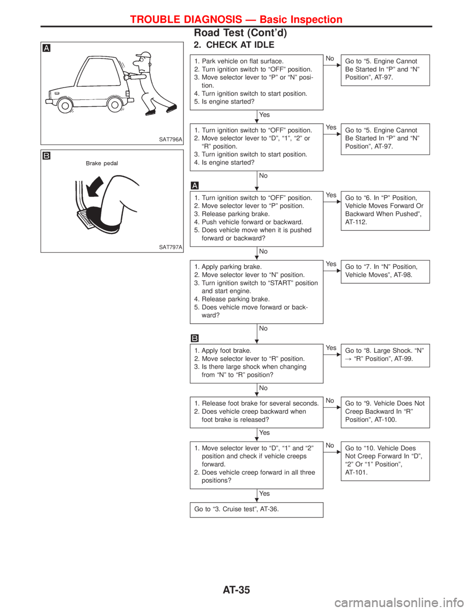
2. CHECK AT IDLE
1. Park vehicle on flat surface.
2. Turn ignition switch to ªOFFº position.
3. Move selector lever to ªPº or ªNº posi-
tion.
4. Turn ignition switch to start position.
5. Is engine started?
Ye s
ENo
Go to ª5. Engine Cannot
Be Started In ªPº and ªNº
Positionº, AT-97.
1. Turn ignition switch to ªOFFº position.
2. Move selector lever to ªDº, ª1º, ª2º or
ªRº position.
3. Turn ignition switch to start position.
4. Is engine started?
No
EYe s
Go to ª5. Engine Cannot
Be Started In ªPº and ªNº
Positionº, AT-97.
1. Turn ignition switch to ªOFFº position.
2. Move selector lever to ªPº position.
3. Release parking brake.
4. Push vehicle forward or backward.
5. Does vehicle move when it is pushed
forward or backward?
No
EYe s
Go to ª6. In ªPº Position,
Vehicle Moves Forward Or
Backward When Pushedº,
AT-112.
1. Apply parking brake.
2. Move selector lever to ªNº position.
3. Turn ignition switch to ªSTARTº position
and start engine.
4. Release parking brake.
5. Does vehicle move forward or back-
ward?
No
EYe s
Go to ª7. In ªNº Position,
Vehicle Movesº, AT-98.
1. Apply foot brake.
2. Move selector lever to ªRº position.
3. Is there large shock when changing
from ªNº to ªRº position?
No
EYe s
Go to ª8. Large Shock. ªNº
,ªRº Positionº, AT-99.
1. Release foot brake for several seconds.
2. Does vehicle creep backward when
foot brake is released?
Ye s
ENo
Go to ª9. Vehicle Does Not
Creep Backward In ªRº
Positionº, AT-100.
1. Move selector lever to ªDº, ª1º and ª2º
position and check if vehicle creeps
forward.
2. Does vehicle creep forward in all three
positions?
Ye s
ENo
Go to ª10. Vehicle Does
Not Creep Forward In ªDº,
ª2º Or ª1º Positionº,
AT-101.
Go to ª3. Cruise testº, AT-36.
SAT796A
SAT797A
H
H
H
H
H
H
H
TROUBLE DIAGNOSIS Ð Basic Inspection
Road Test (Cont'd)
AT-35
Page 52 of 1767
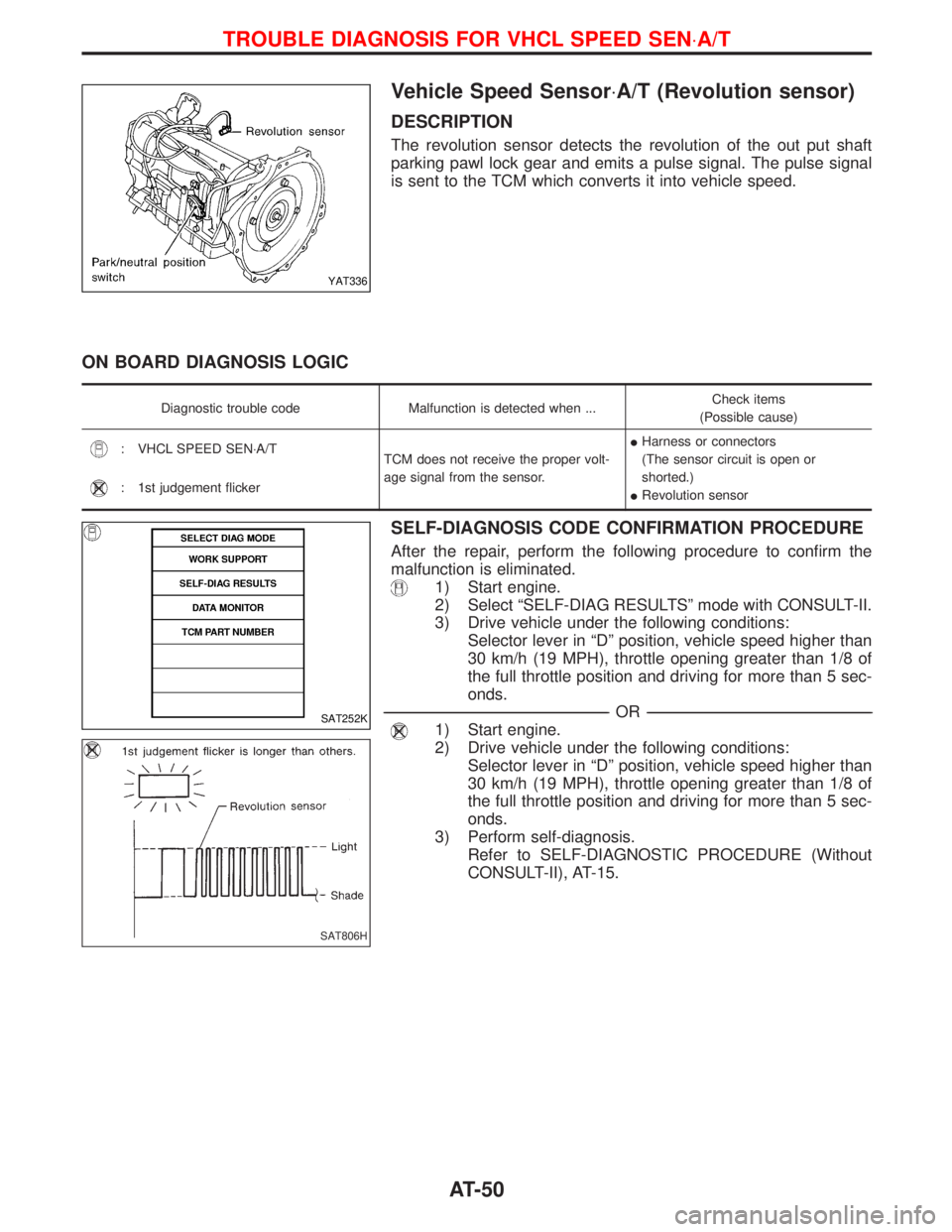
Vehicle Speed Sensor×A/T (Revolution sensor)
DESCRIPTION
The revolution sensor detects the revolution of the out put shaft
parking pawl lock gear and emits a pulse signal. The pulse signal
is sent to the TCM which converts it into vehicle speed.
ON BOARD DIAGNOSIS LOGIC
Diagnostic trouble code Malfunction is detected when ...Check items
(Possible cause)
: VHCL SPEED SEN×A/T
TCM does not receive the proper volt-
age signal from the sensor.IHarness or connectors
(The sensor circuit is open or
shorted.)
IRevolution sensor
: 1st judgement flicker
SELF-DIAGNOSIS CODE CONFIRMATION PROCEDURE
After the repair, perform the following procedure to confirm the
malfunction is eliminated.
1) Start engine.
2) Select ªSELF-DIAG RESULTSº mode with CONSULT-II.
3) Drive vehicle under the following conditions:
Selector lever in ªDº position, vehicle speed higher than
30 km/h (19 MPH), throttle opening greater than 1/8 of
the full throttle position and driving for more than 5 sec-
onds.
------------------------------------------------------------------------------------------------------------------------------------------------------------------------------------------------------------------------------------------------------------OR------------------------------------------------------------------------------------------------------------------------------------------------------------------------------------------------------------------------------------------------------------
1) Start engine.
2) Drive vehicle under the following conditions:
Selector lever in ªDº position, vehicle speed higher than
30 km/h (19 MPH), throttle opening greater than 1/8 of
the full throttle position and driving for more than 5 sec-
onds.
3) Perform self-diagnosis.
Refer to SELF-DIAGNOSTIC PROCEDURE (Without
CONSULT-II), AT-15.
YAT336
SAT252K
SAT806H
TROUBLE DIAGNOSIS FOR VHCL SPEED SEN×A/T
AT-50
Page 53 of 1767
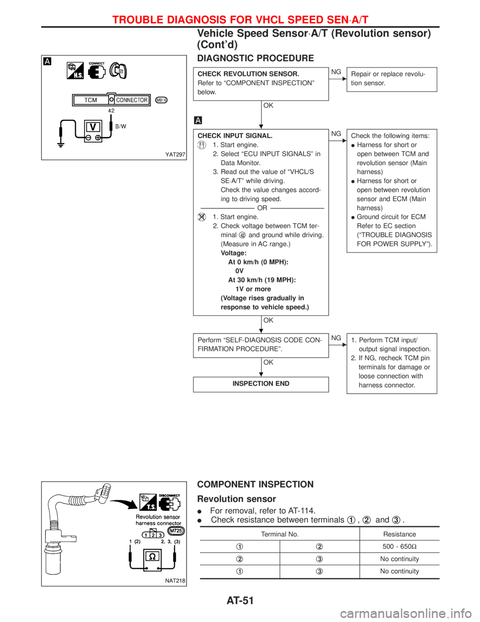
DIAGNOSTIC PROCEDURE
CHECK REVOLUTION SENSOR.
Refer to ªCOMPONENT INSPECTIONº
below.
OK
ENG
Repair or replace revolu-
tion sensor.
CHECK INPUT SIGNAL.
1. Start engine.
2. Select ªECU INPUT SIGNALSº in
Data Monitor.
3. Read out the value of ªVHCL/S
SE×A/Tº while driving.
Check the value changes accord-
ing to driving speed.
-----------------------------------------------------------------------------------------------------------------------OR -----------------------------------------------------------------------------------------------------------------------
1. Start engine.
2. Check voltage between TCM ter-
minalq
42and ground while driving.
(Measure in AC range.)
Voltage:
At 0 km/h (0 MPH):
0V
At 30 km/h (19 MPH):
1V or more
(Voltage rises gradually in
response to vehicle speed.)
OK
ENG
Check the following items:
IHarness for short or
open between TCM and
revolution sensor (Main
harness)
IHarness for short or
open between revolution
sensor and ECM (Main
harness)
IGround circuit for ECM
Refer to EC section
(ªTROUBLE DIAGNOSIS
FOR POWER SUPPLYº).
Perform ªSELF-DIAGNOSIS CODE CON-
FIRMATION PROCEDUREº.
OK
ENG
1. Perform TCM input/
output signal inspection.
2. If NG, recheck TCM pin
terminals for damage or
loose connection with
harness connector.
INSPECTION END
COMPONENT INSPECTION
Revolution sensor
IFor removal, refer to AT-114.
ICheck resistance between terminalsq
1,q2andq3.
Terminal No. Resistance
q
1q2500 - 650W
q
2q3No continuity
q
1q3No continuity
YAT297
NAT218
H
H
H
TROUBLE DIAGNOSIS FOR VHCL SPEED SEN×A/T
Vehicle Speed Sensor×A/T (Revolution sensor)
(Cont'd)
AT-51
Page 56 of 1767
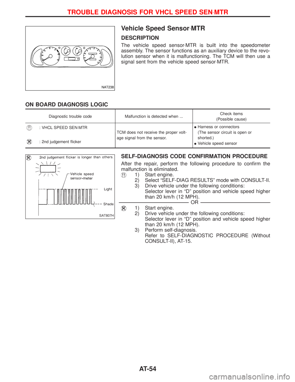
Vehicle Speed Sensor×MTR
DESCRIPTION
The vehicle speed sensor×MTR is built into the speedometer
assembly. The sensor functions as an auxiliary device to the revo-
lution sensor when it is malfunctioning. The TCM will then use a
signal sent from the vehicle speed sensor×MTR.
ON BOARD DIAGNOSIS LOGIC
Diagnostic trouble code Malfunction is detected when ...Check items
(Possible cause)
: VHCL SPEED SEN×MTR
TCM does not receive the proper volt-
age signal from the sensor.IHarness or connectors
(The sensor circuit is open or
shorted.)
IVehicle speed sensor
: 2nd judgement flicker
SELF-DIAGNOSIS CODE CONFIRMATION PROCEDURE
After the repair, perform the following procedure to confirm the
malfunction is eliminated.
1) Start engine.
2) Select ªSELF-DIAG RESULTSº mode with CONSULT-II.
3) Drive vehicle under the following conditions:
Selector lever in ªDº position and vehicle speed higher
than 20 km/h (12 MPH).
------------------------------------------------------------------------------------------------------------------------------------------------------------------------------------------------------------------------------------------------------------OR------------------------------------------------------------------------------------------------------------------------------------------------------------------------------------------------------------------------------------------------------------
1) Start engine.
2) Drive vehicle under the following conditions:
Selector lever in ªDº position and vehicle speed higher
than 20 km/h (12 MPH).
3) Perform self-diagnosis.
Refer to SELF-DIAGNOSTIC PROCEDURE (Without
CONSULT-II), AT-15.
NAT238
SAT807H
TROUBLE DIAGNOSIS FOR VHCL SPEED SEN×MTR
AT-54
Page 57 of 1767
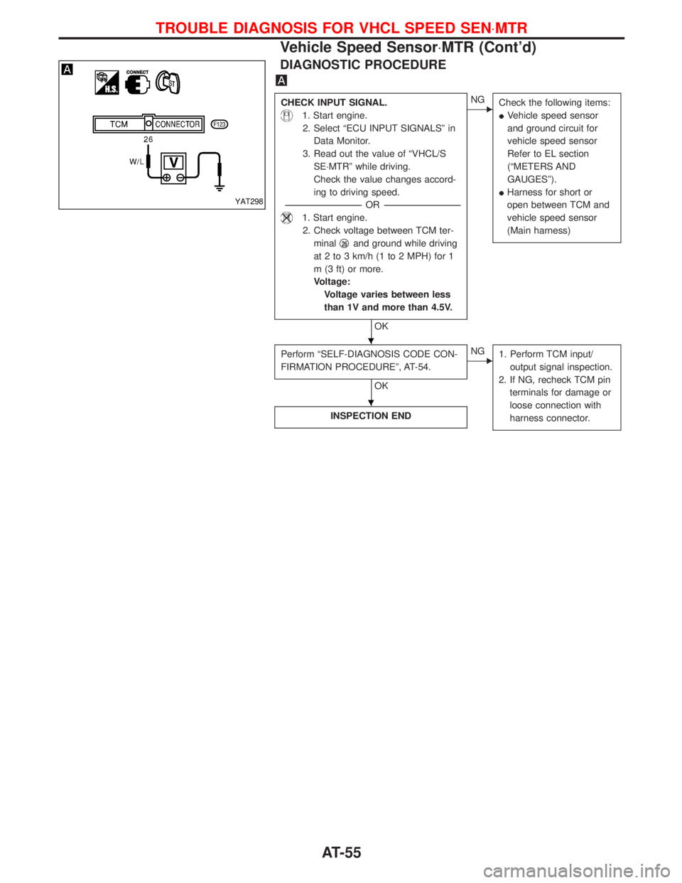
DIAGNOSTIC PROCEDURE
CHECK INPUT SIGNAL.
1. Start engine.
2. Select ªECU INPUT SIGNALSº in
Data Monitor.
3. Read out the value of ªVHCL/S
SE×MTRº while driving.
Check the value changes accord-
ing to driving speed.
-----------------------------------------------------------------------------------------------------------------------OR -----------------------------------------------------------------------------------------------------------------------
1. Start engine.
2. Check voltage between TCM ter-
minalq
26and ground while driving
at 2 to 3 km/h (1 to 2 MPH) for 1
m (3 ft) or more.
Voltage:
Voltage varies between less
than 1V and more than 4.5V.
OK
ENG
Check the following items:
IVehicle speed sensor
and ground circuit for
vehicle speed sensor
Refer to EL section
(ªMETERS AND
GAUGESº).
IHarness for short or
open between TCM and
vehicle speed sensor
(Main harness)
Perform ªSELF-DIAGNOSIS CODE CON-
FIRMATION PROCEDUREº, AT-54.
OK
ENG
1. Perform TCM input/
output signal inspection.
2. If NG, recheck TCM pin
terminals for damage or
loose connection with
harness connector.
INSPECTION END
YAT298
H
H
TROUBLE DIAGNOSIS FOR VHCL SPEED SEN×MTR
Vehicle Speed Sensor×MTR (Cont'd)
AT-55