Page 219 of 1767

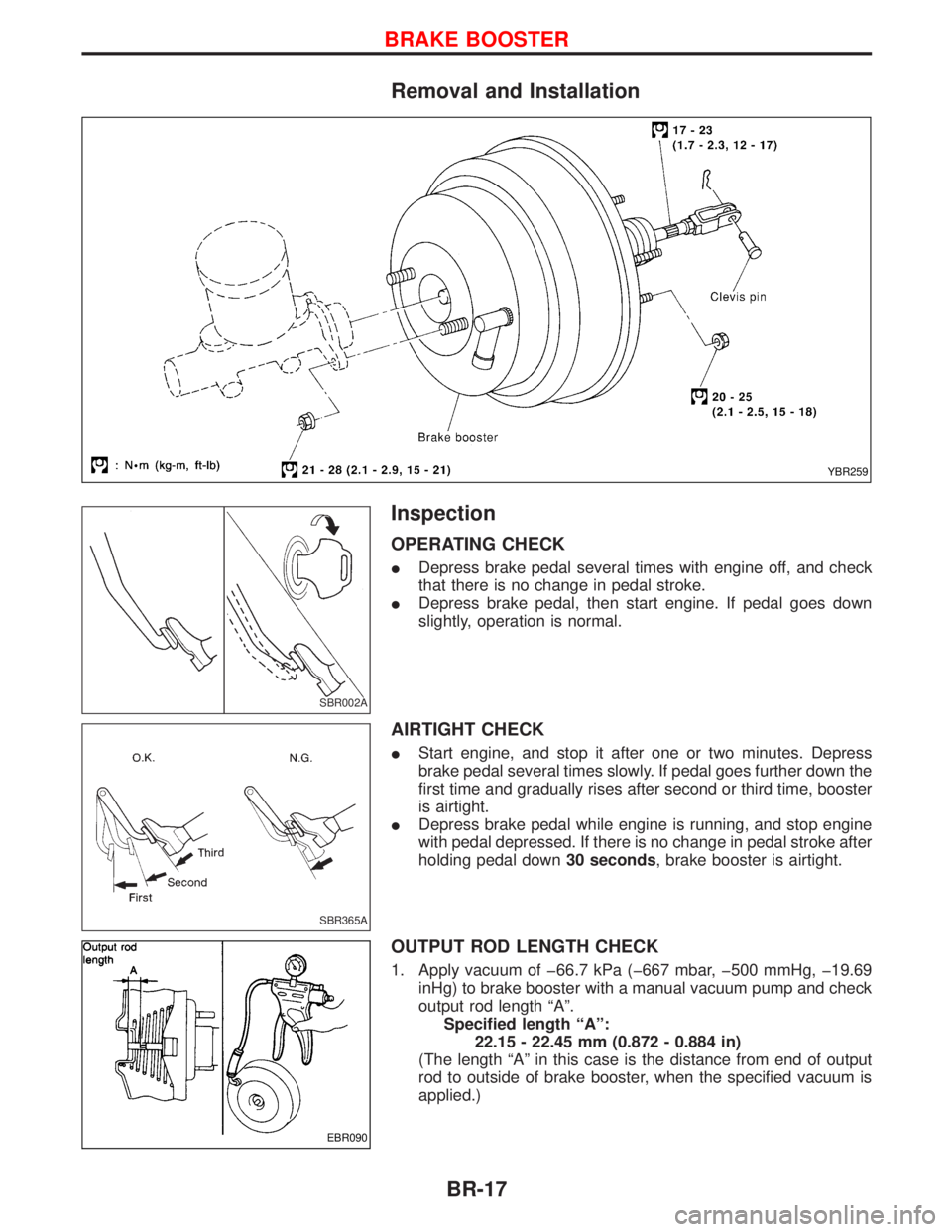
Removal and Installation
Inspection
OPERATING CHECK
IDepress brake pedal several times with engine off, and check
that there is no change in pedal stroke.
IDepress brake pedal, then start engine. If pedal goes down
slightly, operation is normal.
AIRTIGHT CHECK
IStart engine, and stop it after one or two minutes. Depress
brake pedal several times slowly. If pedal goes further down the
first time and gradually rises after second or third time, booster
is airtight.
IDepress brake pedal while engine is running, and stop engine
with pedal depressed. If there is no change in pedal stroke after
holding pedal down30 seconds, brake booster is airtight.
OUTPUT ROD LENGTH CHECK
1. Apply vacuum of þ66.7 kPa (þ667 mbar, þ500 mmHg, þ19.69
inHg) to brake booster with a manual vacuum pump and check
output rod length ªAº.
Specified length ªAº:
22.15 - 22.45 mm (0.872 - 0.884 in)
(The length ªAº in this case is the distance from end of output
rod to outside of brake booster, when the specified vacuum is
applied.)
YBR259
SBR002A
SBR365A
EBR090
BRAKE BOOSTER
BR-17
Page 223 of 1767
Inspection
HOSES AND CONNECTORS
ICheck condition of vacuum hoses and connectors.
ICheck vacuum hoses and check valve for air tightness.
CHECK VALVE
ICheck vacuum with a manual vacuum pump.
Connect to booster
sideVacuum should exist.
Connect to engine
sideVacuum should not exist.
VACUUM WARNING SWITCH
Test continuity though vacuum warning switch with an ohmmeter
and vacuum pump.
VacuumLess than 26.7 kPa
(267 mbar, 200 mmHg,
7.87 inHg)0W
33.3 kPa
(333 mbar, 250 mmHg,
9.84 inHg) or more
W
EBR008
EBR009
SBR007A
VACUUM HOSE
BR-21
Page 224 of 1767
VACUUM PUMP (TD27Ti ENGINE)
1. Install vacuum gauge.
2. Run engine at 1,000 rpm or more.
3. Check vacuum.
Specified vacuum:
93.3 kPa
(933 mbar, 700 mmHg, 27.56 inHg) or more
VACUUM PUMP (ZD30DDTi ENGINE)
Refer to EM section, ªINSPECTIONº in ªVACUUM PUMP Ð
Removal and Installationº.
NBR004
VACUUM HOSE
Inspection (Cont'd)
BR-22
Page 225 of 1767
Removal and Installation
IDrain oil from vacuum pump before removal.
Manually rotate fan belt clockwise to discharge any oil which
may have accumulated in vacuum pump.
IInstall vane so that its round surface faces pump housing.
IAfter installing vacuum pump assembly, apply 5 m(0.2 Imp fl
oz) of engine oil into vacuum pump assembly. Then, make sure
that pulley can be smoothly rotated by hand.
Inspection
Clean all parts and check them as follows:
ICheck for wear or scratches on mating surfaces of rotor and
vacuum pump housing and on rotor and center plate. If wear
or scratches are noted, replace those parts.
ICheck for wear or scratches on vanes. If necessary, replace.
NBR131
NBR132
NBR133
VACUUM PUMP (TD27Ti engine model)
BR-23
Page 226 of 1767
ICheck inner wall of vacuum pump housing for wear. If
necessary, replace.
ICheck rotor shaft for wear. If necessary, replace.
ICheck valve locations and copper washers for bends or defor-
mation. If necessary, replace.
ICheck that valve operates smoothly when slightly pushed.
Replace if necessary.
ICheck for air leakage with 98 to 490 kPa (1.0 to 4.9 bar, 1 to
5 kg/cm
2, 14 to 71 psi) of air pressure.
Replace if necessary.
NBR134
SBR194
SBR195
VACUUM PUMP (TD27Ti engine model)
Inspection (Cont'd)
BR-24
Page 237 of 1767

Removal and Installation
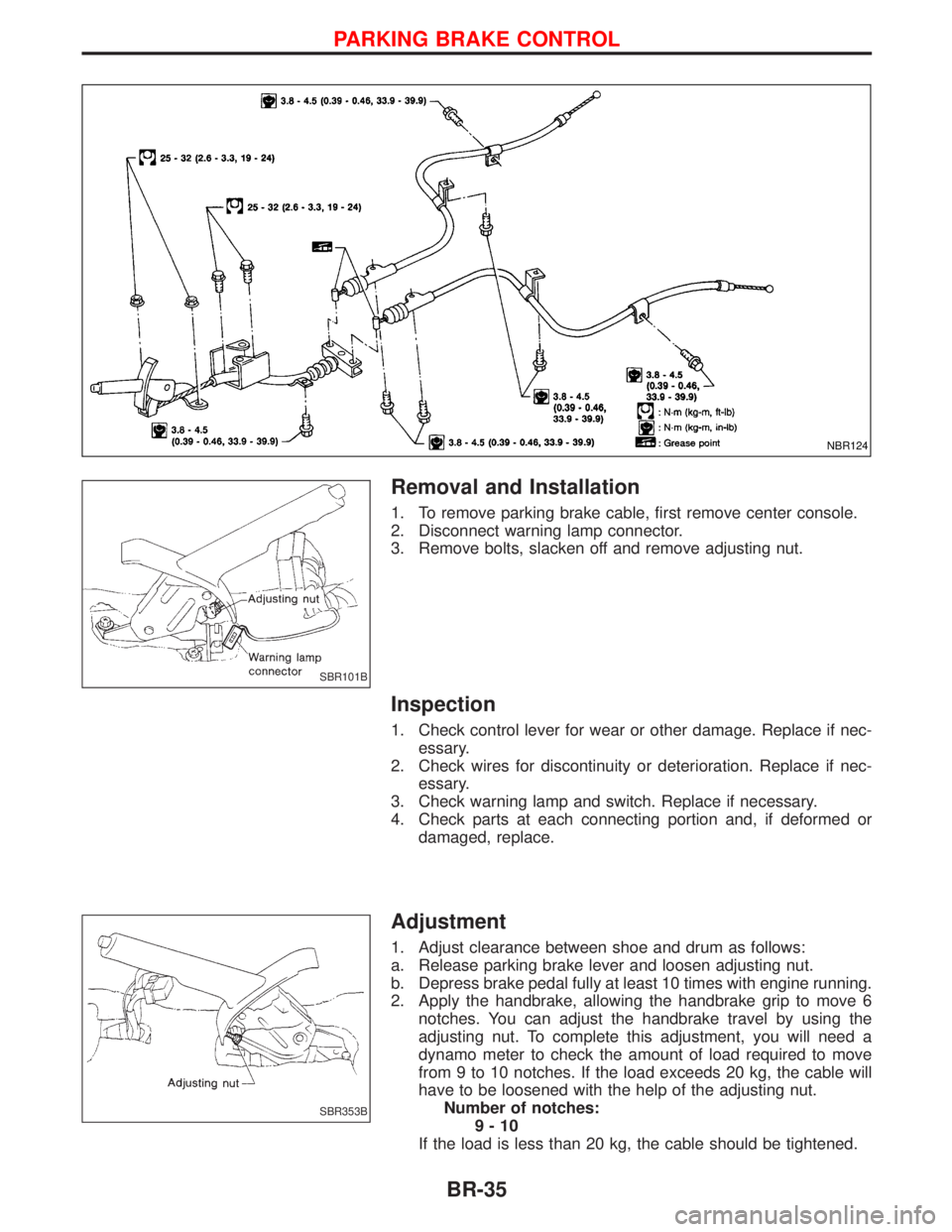
1. To remove parking brake cable, first remove center console.
2. Disconnect warning lamp connector.
3. Remove bolts, slacken off and remove adjusting nut.
Inspection
1. Check control lever for wear or other damage. Replace if nec-
essary.
2. Check wires for discontinuity or deterioration. Replace if nec-
essary.
3. Check warning lamp and switch. Replace if necessary.
4. Check parts at each connecting portion and, if deformed or
damaged, replace.
Adjustment
1. Adjust clearance between shoe and drum as follows:
a. Release parking brake lever and loosen adjusting nut.
b. Depress brake pedal fully at least 10 times with engine running.
2. Apply the handbrake, allowing the handbrake grip to move 6
notches. You can adjust the handbrake travel by using the
adjusting nut. To complete this adjustment, you will need a
dynamo meter to check the amount of load required to move
from 9 to 10 notches. If the load exceeds 20 kg, the cable will
have to be loosened with the help of the adjusting nut.
Number of notches:
9-10
If the load is less than 20 kg, the cable should be tightened.
NBR124
SBR101B
SBR353B
PARKING BRAKE CONTROL
BR-35
Page 239 of 1767

Purpose
The Anti-lock Brake System (ABS) with an integrated Electronic Brake force Distribution (EBD) system con-
sists of electronic and hydraulic components. It allows you to control the braking force so that wheel lock can
be avoided during braking.
The advantages of ABS with EBD
1) Better tracking performance through improved steering wheel control.
2) Improved maneuverability and safer vehicle control.
3) Improved vehicle stability by preventing flat spins.
4) Shorter stopping distance and optimal utilisation of the rear brakes under many different circumstances.
Operation
IABS with EBD has self-test capabilities. The ABS warning lamp is illuminated for 1 second each time the
ignition switch is turned ªONº. After the engine is started, the ABS warning lamp turns off. An ABS self-test
is performed the first time the vehicle reaches 6 km/h (4 MPH) to ensure the system is operational. A
mechanical noise may be heard as the ABS performs this self-test and is a normal part of the self-test
feature. If a malfunction is detected during this check, the ABS warning lamp will stay on.
During the self-test, it also performs a EBD check when it detects a failure the ABS warning light will go
on simultaneously with the brake warning light and an audible sound will sound constantly.
IEBD system will only operate when the ABS is not in active status and it uses the inlet valves of ABS con-
trol unit to limit the pressure to the rear wheels when they tend to go into slip.
IWhen the vehicle speed is less than 10 km/h (6 MPH) the ABS system does not operate.
IWhile driving, a mechanical noise may be heard during ABS operation, this is a normal system condition.
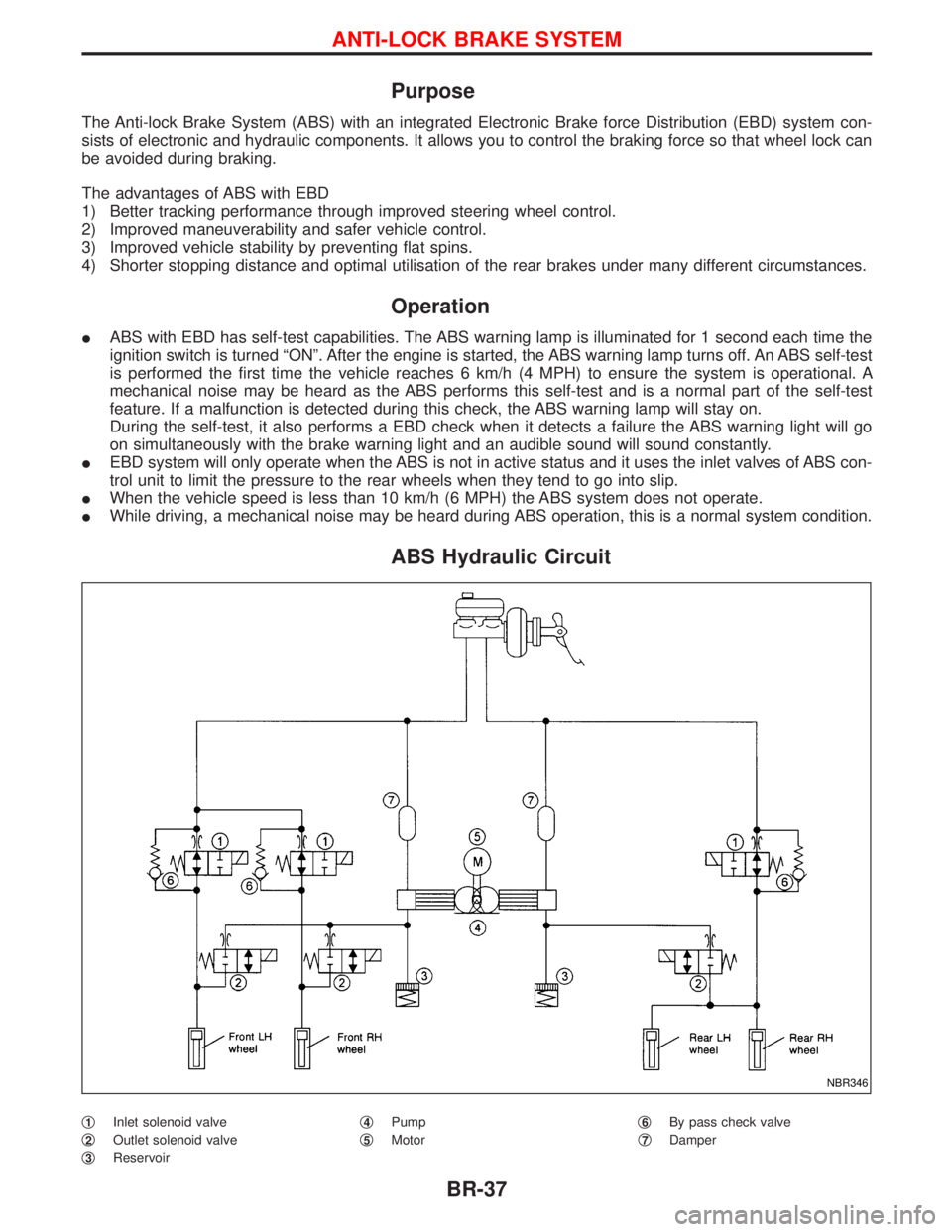
ABS Hydraulic Circuit
q1Inlet solenoid valve
q
2Outlet solenoid valve
q
3Reservoirq
4Pump
q
5Motorq
6By pass check valve
q
7Damper
NBR346
ANTI-LOCK BRAKE SYSTEM
BR-37
Page 261 of 1767

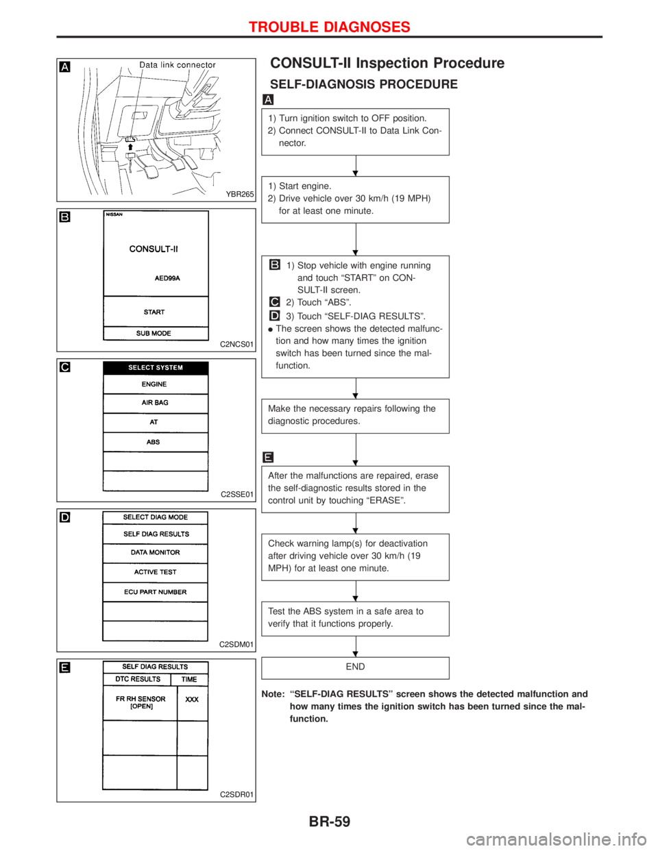
CONSULT-II Inspection Procedure
SELF-DIAGNOSIS PROCEDURE
1) Turn ignition switch to OFF position.
2) Connect CONSULT-II to Data Link Con-
nector.
1) Start engine.
2) Drive vehicle over 30 km/h (19 MPH)
for at least one minute.
1) Stop vehicle with engine running
and touch ªSTARTº on CON-
SULT-II screen.
2) Touch ªABSº.
3) Touch ªSELF-DIAG RESULTSº.
IThe screen shows the detected malfunc-
tion and how many times the ignition
switch has been turned since the mal-
function.
Make the necessary repairs following the
diagnostic procedures.
After the malfunctions are repaired, erase
the self-diagnostic results stored in the
control unit by touching ªERASEº.
Check warning lamp(s) for deactivation
after driving vehicle over 30 km/h (19
MPH) for at least one minute.
Test the ABS system in a safe area to
verify that it functions properly.
END
Note: ªSELF-DIAG RESULTSº screen shows the detected malfunction and
how many times the ignition switch has been turned since the mal-
function.
YBR265
C2NCS01
C2SSE01
C2SDM01
C2SDR01
H
H
H
H
H
H
H
TROUBLE DIAGNOSES
BR-59