2002 NISSAN TERRANO ignition
[x] Cancel search: ignitionPage 1407 of 1767
Diagnostic Procedure 2
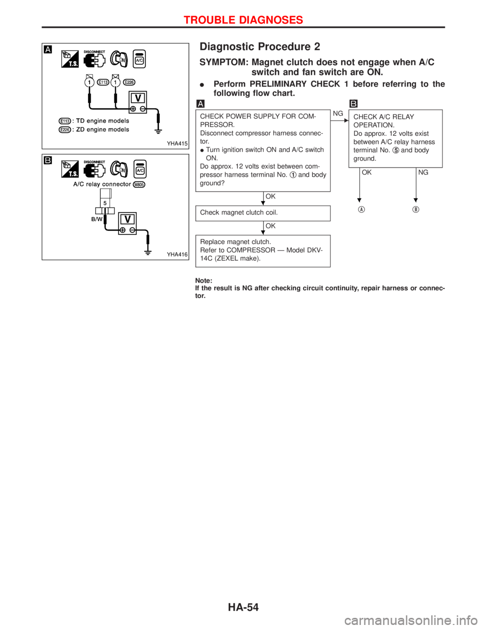
SYMPTOM: Magnet clutch does not engage when A/C
switch and fan switch are ON.
IPerform PRELIMINARY CHECK 1 before referring to the
following flow chart.
CHECK POWER SUPPLY FOR COM-
PRESSOR.
Disconnect compressor harness connec-
tor.
ITurn ignition switch ON and A/C switch
ON.
Do approx. 12 volts exist between com-
pressor harness terminal No.q
1and body
ground?
OK
ENG
CHECK A/C RELAY
OPERATION.
Do approx. 12 volts exist
between A/C relay harness
terminal No.q
5and body
ground.
OK NG
Check magnet clutch coil.
OKq
AqB
Replace magnet clutch.
Refer to COMPRESSOR Ð Model DKV-
14C (ZEXEL make).
Note:
If the result is NG after checking circuit continuity, repair harness or connec-
tor.
YHA415
YHA416
HHH
H
TROUBLE DIAGNOSES
HA-54
Page 1408 of 1767
qAqB
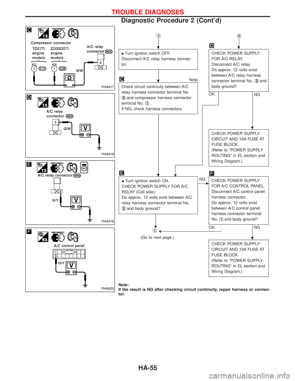
ITurn ignition switch OFF.
Disconnect A/C relay harness connec-
tor.CHECK POWER SUPPLY
FOR A/C RELAY.
Disconnect A/C relay.
Do approx. 12 volts exist
between A/C relay harness
connector terminal No.q
3and
body ground?
NG OK
Note
Check circuit continuity between A/C
relay harness connector terminal No.
q
5and compressor harness connector
terminal No.q
1.
If NG, check harness connectors.
H
CHECK POWER SUPPLY
CIRCUIT AND 10A FUSE AT
FUSE BLOCK.
(Refer to ªPOWER SUPPLY
ROUTINGº in EL section and
Wiring Diagram.)
ITurn ignition switch ON.
CHECK POWER SUPPLY FOR A/C
RELAY (Coil side).
Do approx. 12 volts exist between A/C
relay harness connector terminal No.
q
2and body ground?
H
ENG
CHECK POWER SUPPLY
FOR A/C CONTROL PANEL.
Disconnect A/C control panel
harness connector.
Do approx. 12 volts exist
between A/C control panel
harness connector terminal
No.q
1and body ground?
NG
OKFqC
(Go to next page.)
CHECK POWER SUPPLY
CIRCUIT AND 10A FUSE AT
FUSE BLOCK.
(Refer to ªPOWER SUPPLY
ROUTINGº in EL section and
Wiring Diagram.)
Note:
If the result is NG after checking circuit continuity, repair harness or connec-
tor.
YHA417
YHA418
YHA419
YHA420
HH
H
H
H
H
TROUBLE DIAGNOSES
Diagnostic Procedure 2 (Cont'd)
HA-55
Page 1409 of 1767
qC
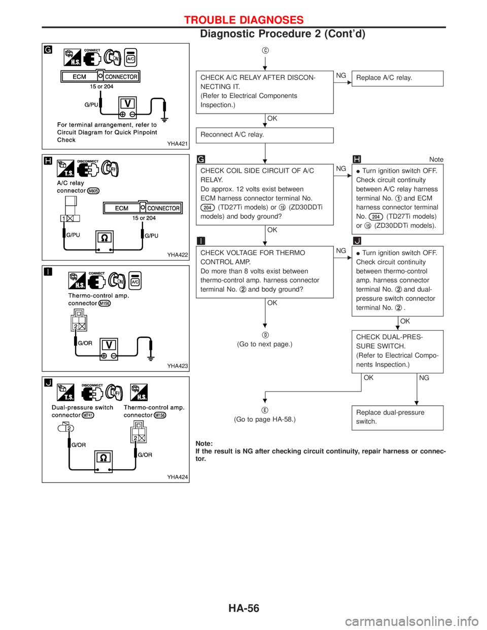
CHECK A/C RELAY AFTER DISCON-
NECTING IT.
(Refer to Electrical Components
Inspection.)
OK
ENG
Replace A/C relay.
Reconnect A/C relay.
Note
CHECK COIL SIDE CIRCUIT OF A/C
RELAY.
Do approx. 12 volts exist between
ECM harness connector terminal No.
204(TD27Ti models) orq15(ZD30DDTi
models) and body ground?
OK
ENG
ITurn ignition switch OFF.
Check circuit continuity
between A/C relay harness
terminal No.q
1and ECM
harness connector terminal
No.
204(TD27Ti models)
orq
15(ZD30DDTi models).
CHECK VOLTAGE FOR THERMO
CONTROL AMP.
Do more than 8 volts exist between
thermo-control amp. harness connector
terminal No.q
2and body ground?
OK
ENG
ITurn ignition switch OFF.
Check circuit continuity
between thermo-control
amp. harness connector
terminal No.q
2and dual-
pressure switch connector
terminal No.q
2.
OK
q
D
(Go to next page.)CHECK DUAL-PRES-
SURE SWITCH.
(Refer to Electrical Compo-
nents Inspection.)
NGOK
q
E
(Go to page HA-58.)Replace dual-pressure
switch.
Note:
If the result is NG after checking circuit continuity, repair harness or connec-
tor.
YHA421
YHA422
YHA423
YHA424
H
H
H
H
HH
HH
TROUBLE DIAGNOSES
Diagnostic Procedure 2 (Cont'd)
HA-56
Page 1410 of 1767
qD
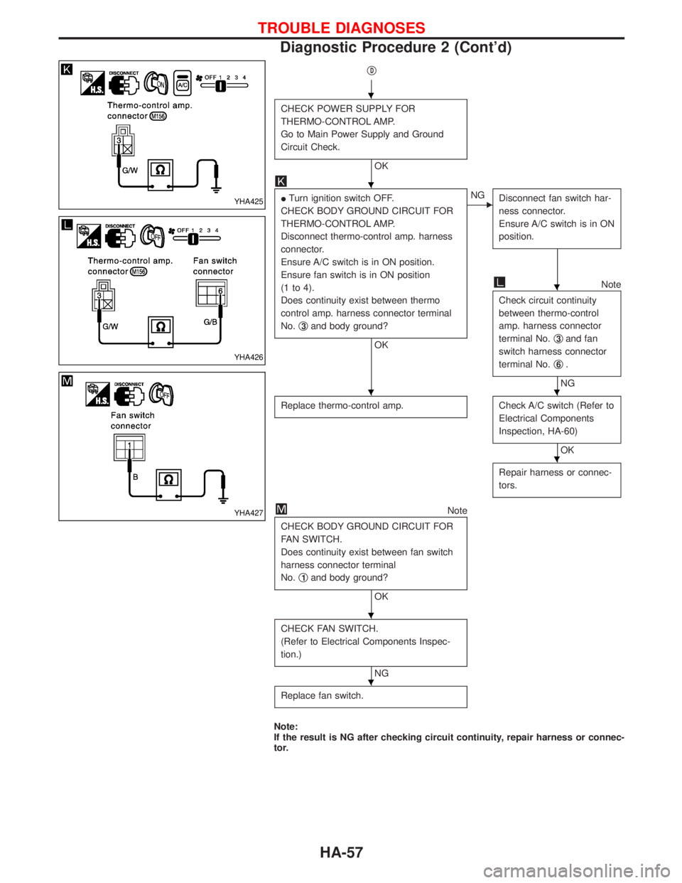
CHECK POWER SUPPLY FOR
THERMO-CONTROL AMP.
Go to Main Power Supply and Ground
Circuit Check.
OK
ITurn ignition switch OFF.
CHECK BODY GROUND CIRCUIT FOR
THERMO-CONTROL AMP.
Disconnect thermo-control amp. harness
connector.
Ensure A/C switch is in ON position.
Ensure fan switch is in ON position
(1 to 4).
Does continuity exist between thermo
control amp. harness connector terminal
No.q
3and body ground?
OK
ENG
Disconnect fan switch har-
ness connector.
Ensure A/C switch is in ON
position.
Note
Check circuit continuity
between thermo-control
amp. harness connector
terminal No.q
3and fan
switch harness connector
terminal No.q
6.
NG
Replace thermo-control amp.
Check A/C switch (Refer to
Electrical Components
Inspection, HA-60)
OK
Repair harness or connec-
tors.
Note
CHECK BODY GROUND CIRCUIT FOR
FAN SWITCH.
Does continuity exist between fan switch
harness connector terminal
No.q
1and body ground?
OK
CHECK FAN SWITCH.
(Refer to Electrical Components Inspec-
tion.)
NG
Replace fan switch.
Note:
If the result is NG after checking circuit continuity, repair harness or connec-
tor.
YHA425
YHA426
YHA427
H
H
H
HH
H
H
H
TROUBLE DIAGNOSES
Diagnostic Procedure 2 (Cont'd)
HA-57
Page 1412 of 1767
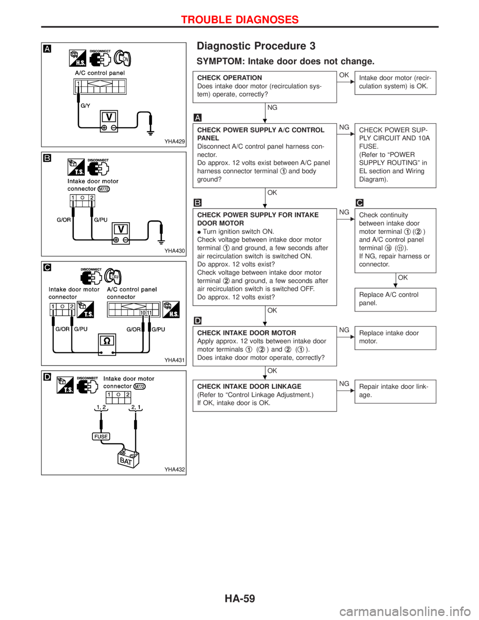
Diagnostic Procedure 3
SYMPTOM: Intake door does not change.
CHECK OPERATION
Does intake door motor (recirculation sys-
tem) operate, correctly?
NG
EOK
Intake door motor (recir-
culation system) is OK.
CHECK POWER SUPPLY A/C CONTROL
PANEL
Disconnect A/C control panel harness con-
nector.
Do approx. 12 volts exist between A/C panel
harness connector terminalq
1and body
ground?
OK
ENG
CHECK POWER SUP-
PLY CIRCUIT AND 10A
FUSE.
(Refer to ªPOWER
SUPPLY ROUTINGº in
EL section and Wiring
Diagram).
CHECK POWER SUPPLY FOR INTAKE
DOOR MOTOR
ITurn ignition switch ON.
Check voltage between intake door motor
terminalq
1and ground, a few seconds after
air recirculation switch is switched ON.
Do approx. 12 volts exist?
Check voltage between intake door motor
terminalq
2and ground, a few seconds after
air recirculation switch is switched OFF.
Do approx. 12 volts exist?
OK
ENG
Check continuity
between intake door
motor terminalq
1(q2)
and A/C control panel
terminalq
10(q11).
If NG, repair harness or
connector.
OK
Replace A/C control
panel.
CHECK INTAKE DOOR MOTOR
Apply approx. 12 volts between intake door
motor terminalsq
1(q2) andq2(q1).
Does intake door motor operate, correctly?
OK
ENG
Replace intake door
motor.
CHECK INTAKE DOOR LINKAGE
(Refer to ªControl Linkage Adjustment.)
If OK, intake door is OK.ENG
Repair intake door link-
age.
YHA429
YHA430
YHA431
YHA432
H
H
H
H
H
TROUBLE DIAGNOSES
HA-59
Page 1462 of 1767
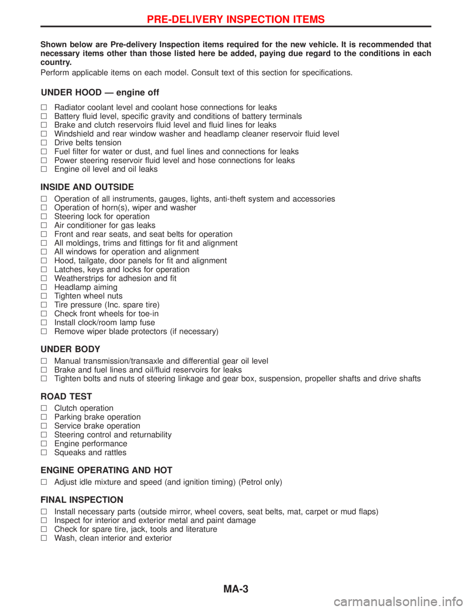
Shown below are Pre-delivery Inspection items required for the new vehicle. It is recommended that
necessary items other than those listed here be added, paying due regard to the conditions in each
country.
Perform applicable items on each model. Consult text of this section for specifications.
UNDER HOOD Ð engine off
lRadiator coolant level and coolant hose connections for leaks
lBattery fluid level, specific gravity and conditions of battery terminals
lBrake and clutch reservoirs fluid level and fluid lines for leaks
lWindshield and rear window washer and headlamp cleaner reservoir fluid level
lDrive belts tension
lFuel filter for water or dust, and fuel lines and connections for leaks
lPower steering reservoir fluid level and hose connections for leaks
lEngine oil level and oil leaks
INSIDE AND OUTSIDE
lOperation of all instruments, gauges, lights, anti-theft system and accessories
lOperation of horn(s), wiper and washer
lSteering lock for operation
lAir conditioner for gas leaks
lFront and rear seats, and seat belts for operation
lAll moldings, trims and fittings for fit and alignment
lAll windows for operation and alignment
lHood, tailgate, door panels for fit and alignment
lLatches, keys and locks for operation
lWeatherstrips for adhesion and fit
lHeadlamp aiming
lTighten wheel nuts
lTire pressure (Inc. spare tire)
lCheck front wheels for toe-in
lInstall clock/room lamp fuse
lRemove wiper blade protectors (if necessary)
UNDER BODY
lManual transmission/transaxle and differential gear oil level
lBrake and fuel lines and oil/fluid reservoirs for leaks
lTighten bolts and nuts of steering linkage and gear box, suspension, propeller shafts and drive shafts
ROAD TEST
lClutch operation
lParking brake operation
lService brake operation
lSteering control and returnability
lEngine performance
lSqueaks and rattles
ENGINE OPERATING AND HOT
lAdjust idle mixture and speed (and ignition timing) (Petrol only)
FINAL INSPECTION
lInstall necessary parts (outside mirror, wheel covers, seat belts, mat, carpet or mud flaps)
lInspect for interior and exterior metal and paint damage
lCheck for spare tire, jack, tools and literature
lWash, clean interior and exterior
PRE-DELIVERY INSPECTION ITEMS
MA-3
Page 1623 of 1767
Precautions
SUPPLEMENTAL RESTRAINT SYSTEM (SRS) ªAIR BAGº AND ªSEAT BELT
PRE-TENSIONERº
The Supplemental Restraint System such as ªAIR BAGº and ªSEAT BELT PRE-TENSIONERº used along with
a seat belt, helps to reduce the risk or severity of injury to the driver and front passenger for certain types of
collision. The SRS composition which is available to NISSAN MODEL R20 is as follows (The composition
varies according to the destination and optional equipment.):
IFor a frontal collision
The Supplemental Restraint System consists of driver air bag module (located in the center of the steer-
ing wheel), front passenger air bag module (located on the instrument panel on passenger side), front seat
belt pre-tensioners, a diagnosis sensor unit, warning lamp, wiring harness and spiral cable.
IFor a side collision
The Supplemental Restraint System consists of front side air bag module (located in the outer side of front
seat), side air bag (satellite) sensor, diagnosis sensor unit (one of components of air bags for a frontal
collision), wiring harness, warning lamp (one of components of air bags for a frontal collision).
WARNING:
ITo avoid rendering the SRS inoperative, which could increase the risk of personal injury or death
in the event of a collision which would result in air bag inflation, all maintenance should be per-
formed by an authorized NISSAN dealer.
IImproper maintenance, including incorrect removal and installation of the SRS, can lead to per-
sonal injury caused by unintentional activation of the system.
IDo not use electrical test equipment on any circuit related to the SRS unless instructed to in this
Service Manual. Spiral cable and wiring harnesses covered with yellow insulation tape either just
before the harness connectors or for the complete harness are related to the SRS.
Precaution for Seat Belt Service
CAUTION:
IBefore removing the seat belt pre-tensioner assembly, turn the ignition switch off, disconnect both
battery cables and wait at least 3 minutes.
IDo not use electrical test equipment for seat belt pre-tensioner connector.
IAfter replacing or reinstalling seat belt pre-tensioner assembly, or reconnecting seat belt pre-ten-
sioner connector, check the system function. Refer to ªSRS Operation Checkº for details. (RS-36)
IDo not disassemble buckle or seat belt assembly.
IReplace anchor bolts if they are deformed or worn out.
INever oil tongue and buckle.
IIf any component of seat belt assembly is questionable, do not repair. Replace the whole seat belt
assembly.
IIf webbing is cut, frayed, or damaged, replace seat belt assembly.
IWhen replacing seat belt assembly, use a genuine seat belt assembly.
After A Collision
WARNING:
Inspect all seat belt assemblies including retractors and attaching hardware after any collision.
NISSAN recommends that all seat belt assemblies in use during a collision be replaced unless the
collision was minor and the belts show no damage and continue to operate properly. Failure to do so
could result in serious personal injury in an accident. Seat belt assemblies not in use during a colli-
sion should also be replaced if either damage or improper operation is noted. Seat belt pre-tensioner
should be replaced even if the seat belts are not in use during a frontal collision in which the air bags
are deployed.
Replace any seat belt assembly if:
IThe seat belt was in use at the time of a collision (except for minor collisions and the belts, retractors and
buckles show no damage and continue to operate properly).
IThe seat belt was damaged in an accident. (i.e. torn webbing, bent retractor or guide, etc.)
IThe seat belt attaching point was damaged in an accident. Inspect the seat belt attaching area for dam-
age or distortion and repair as necessary before installing a new seat belt assembly.
IAnchor bolts are deformed or worn out.
SEAT BELTS
RS-2
Page 1627 of 1767
Precautions
SUPPLEMENTAL RESTRAINT SYSTEM (SRS) ªAIR BAGº AND ªSEAT BELT
PRE-TENSIONERº
The Supplemental Restraint System such as ªAIR BAGº and ªSEAT BELT PRE-TENSIONERº used along with
a seat belt, helps to reduce the risk or severity of injury to the driver and front passenger for certain types of
collision. The SRS composition which is available to NISSAN MODEL R20 is as follows (The composition
varies according to the destination and optional equipment.):
IFor a frontal collision
The Supplemental Restraint System consists of driver air bag module (located in the center of the steer-
ing wheel), front passenger air bag module (located on the instrument panel on passenger side), front seat
belt pre-tensioners, a diagnosis sensor unit, warning lamp, wiring harness and spiral cable.
IFor a side collision
The Supplemental Restraint System consists of front side air bag module (located in the outer side of front
seat), side air bag (satellite) sensor, diagnosis sensor unit (one of components of air bags for a frontal
collision), wiring harness, warning lamp (one of components of air bags for a frontal collision).
WARNING:
ITo avoid rendering the SRS inoperative, which could increase the risk of personal injury or death
in the event of a collision which would result in air bag inflation, all maintenance should be per-
formed by an authorized NISSAN dealer.
IImproper maintenance, including incorrect removal and installation of the SRS, can lead to per-
sonal injury caused by unintentional activation of the system.
IDo not use electrical test equipment on any circuit related to the SRS unless instructed to in this
Service Manual. Spiral cable and wiring harnesses covered with yellow insulation tape either just
before the harness connectors or for the complete harness are related to the SRS.
PRECAUTIONS FOR SRS ªAIR BAGº AND ªSEAT BELT PRE-TENSIONERº SERVICE
IDo not use electrical test equipment to check SRS circuits unless instructed to in this Service Manual.
IBefore servicing the SRS, turn ignition switch ªOFFº, disconnect both battery cables and wait at least 3
minutes.
For approximately 3 minutes after the cables are removed, it is still possible for the air bag and seat belt
pre-tensioner to deploy. Therefore, do not work on any SRS connectors or wires until at least 3 minutes
have passed.
IDiagnosis sensor unit must always be installed with their arrow marks ª+º pointing towards the front of
the vehicle for proper operation. Also check diagnosis sensor unit for cracks, deformities or rust before
installation and replace as required.
IThe spiral cable must be aligned with the neutral position since its rotations are limited. Do not attempt to
turn steering wheel or column after removal of steering gear.
IHandle air bag module carefully. Always place driver and front passenger air bag modules with the pad
side facing upward and place front side air bag module (built-in type) standing with stud bolt side setting
bottom.
IConduct self-diagnosis to check entire SRS for proper function after replacing any components.
IAfter air bag inflates, the front instrument panel assembly should be replaced if damaged.
WIRING DIAGRAMS AND TROUBLE DIAGNOSIS
When you read wiring diagrams, refer to the following:
IGI-10, ªHOW TO READ WIRING DIAGRAMSº
IEL-6, ªPOWER SUPPLY ROUTINGº for power distribution circuit
When you perform trouble diagnosis, refer to the following:
IGI-25, ªHOW TO FOLLOW TEST GROUPS IN TROUBLE DIAGNOSISº
IGI-22, ªHOW TO PERFORM EFFICIENT DIAGNOSES FOR AN ELECTRICAL INCIDENTº
SUPPLEMENTAL RESTRAINT SYSTEM (SRS)
RS-6