Page 1436 of 1767
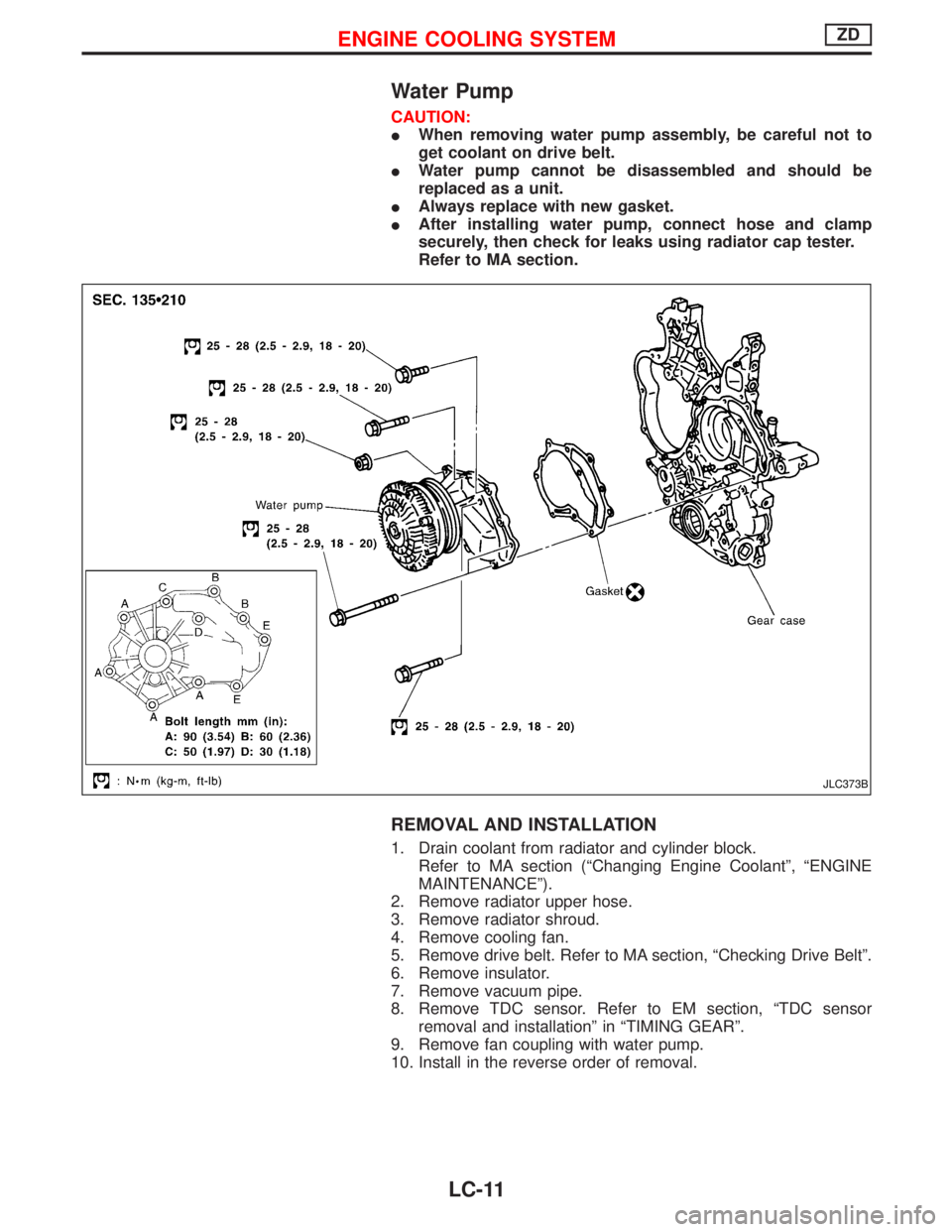
Water Pump
CAUTION:
IWhen removing water pump assembly, be careful not to
get coolant on drive belt.
IWater pump cannot be disassembled and should be
replaced as a unit.
IAlways replace with new gasket.
IAfter installing water pump, connect hose and clamp
securely, then check for leaks using radiator cap tester.
Refer to MA section.
REMOVAL AND INSTALLATION
1. Drain coolant from radiator and cylinder block.
Refer to MA section (ªChanging Engine Coolantº, ªENGINE
MAINTENANCEº).
2. Remove radiator upper hose.
3. Remove radiator shroud.
4. Remove cooling fan.
5. Remove drive belt. Refer to MA section, ªChecking Drive Beltº.
6. Remove insulator.
7. Remove vacuum pipe.
8. Remove TDC sensor. Refer to EM section, ªTDC sensor
removal and installationº in ªTIMING GEARº.
9. Remove fan coupling with water pump.
10. Install in the reverse order of removal.
JLC373B
ENGINE COOLING SYSTEMZD
LC-11
Page 1437 of 1767
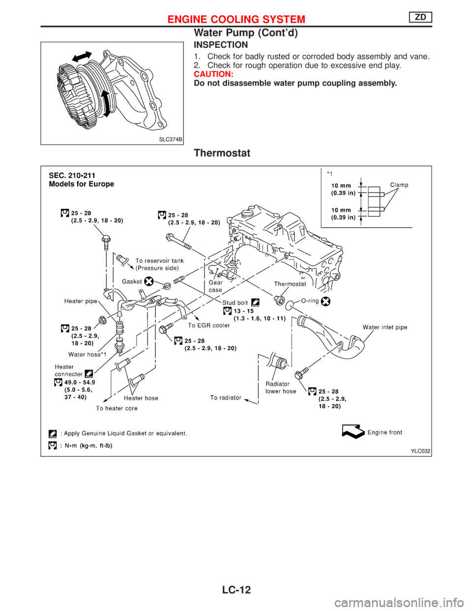
INSPECTION
1. Check for badly rusted or corroded body assembly and vane.
2. Check for rough operation due to excessive end play.
CAUTION:
Do not disassemble water pump coupling assembly.
Thermostat
SLC374B
YLC032
ENGINE COOLING SYSTEMZD
Water Pump (Cont'd)
LC-12
Page 1440 of 1767
REMOVAL AND INSTALLATION
1. Remove under cover.
2. Drain engine coolant. Refer to MA section, ªChanging Engine
Coolantº.
3. Remove air cleaner case, air duct and resonator.
4. Remove battery (right side).
5. Remove radiator shroud (lower).
6. Remove radiator shroud (front).
7. Disconnect radiator hose (upper and lower).
8. Disconnect reservoir tank hose.
9. Disconnect A/T oil cooler hose (Only A/T models).
10. Remove radiator.
11. After repairing or replacing radiator, install all removed parts in
reverse order of removal.
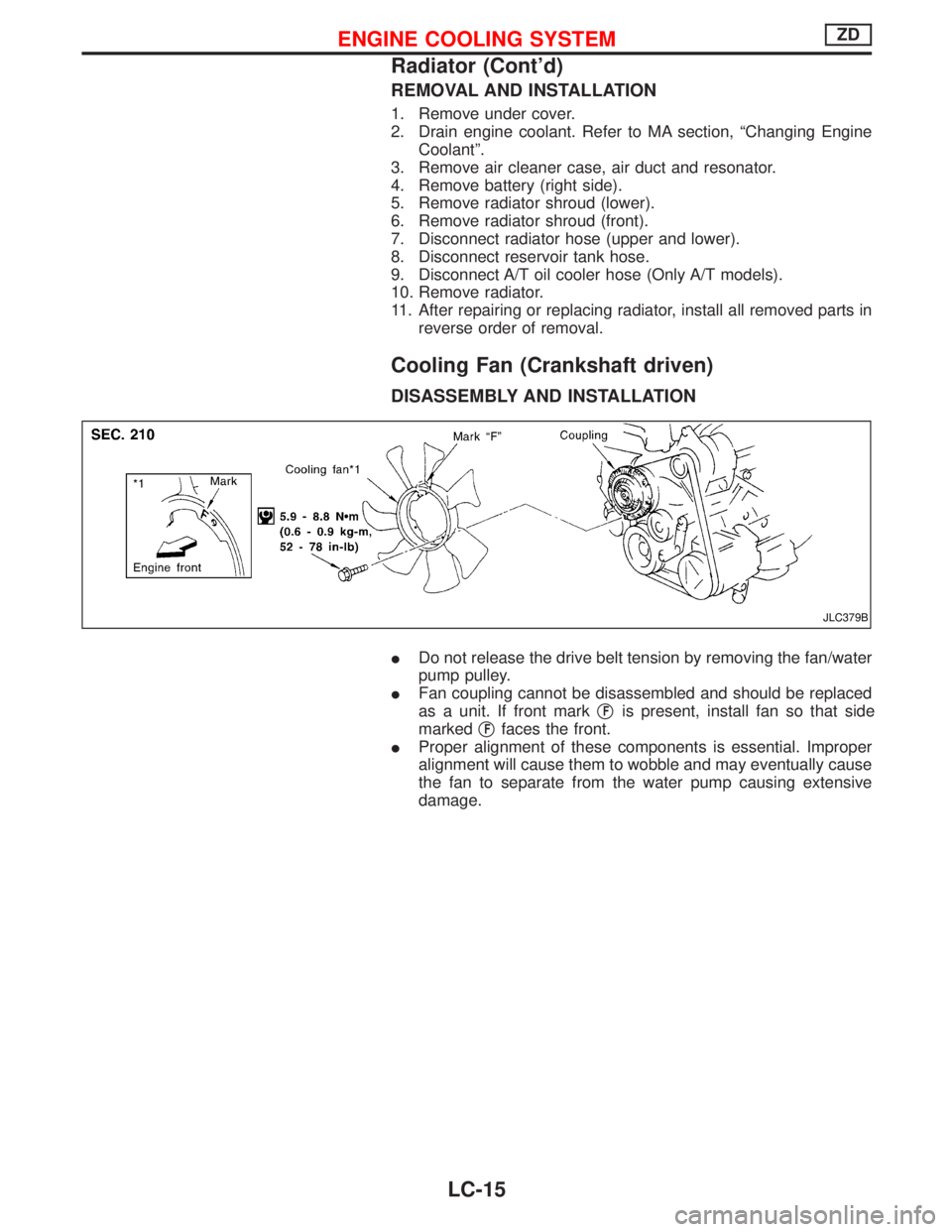
Cooling Fan (Crankshaft driven)
DISASSEMBLY AND INSTALLATION
IDo not release the drive belt tension by removing the fan/water
pump pulley.
IFan coupling cannot be disassembled and should be replaced
as a unit. If front markq
Fis present, install fan so that side
markedq
Ffaces the front.
IProper alignment of these components is essential. Improper
alignment will cause them to wobble and may eventually cause
the fan to separate from the water pump causing extensive
damage.
JLC379B
ENGINE COOLING SYSTEMZD
Radiator (Cont'd)
LC-15
Page 1454 of 1767
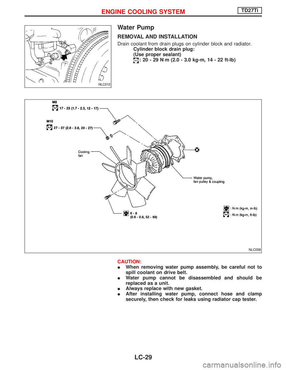
Water Pump
REMOVAL AND INSTALLATION
Drain coolant from drain plugs on cylinder block and radiator.
Cylinder block drain plug:
(Use proper sealant)
:20-29N×m (2.0 - 3.0 kg-m, 14 - 22 ft-lb)
CAUTION:
IWhen removing water pump assembly, be careful not to
spill coolant on drive belt.
IWater pump cannot be disassembled and should be
replaced as a unit.
IAlways replace with new gasket.
IAfter installing water pump, connect hose and clamp
securely, then check for leaks using radiator cap tester.
NLC012
NLC058
ENGINE COOLING SYSTEMTD27Ti
LC-29
Page 1455 of 1767
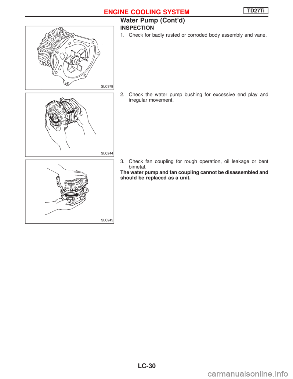
INSPECTION
1. Check for badly rusted or corroded body assembly and vane.
2. Check the water pump bushing for excessive end play and
irregular movement.
3. Check fan coupling for rough operation, oil leakage or bent
bimetal.
The water pump and fan coupling cannot be disassembled and
should be replaced as a unit.
SLC979
SLC244
SLC245
ENGINE COOLING SYSTEMTD27Ti
Water Pump (Cont'd)
LC-30
Page 1483 of 1767
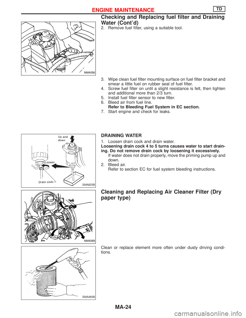
2. Remove fuel filter, using a suitable tool.
3. Wipe clean fuel filter mounting surface on fuel filter bracket and
smear a little fuel on rubber seal of fuel filter.
4. Screw fuel filter on until a slight resistance is felt, then tighten
and additional more than 2/3 turn.
5. Install fuel filter sensor to new filter.
6. Bleed air from fuel line.
Refer to Bleeding Fuel System in EC section.
7. Start engine and check for leaks.
DRAINING WATER
1. Loosen drain cock and drain water.
Loosening drain cock 4 to 5 turns causes water to start drain-
ing. Do not remove drain cock by loosening it excessively.
If water does not drain properly, move the priming pump up and
down.
2. Bleed air.
Refer to section EC for fuel system bleeding instructions.
Cleaning and Replacing Air Cleaner Filter (Dry
paper type)
Clean or replace element more often under dusty driving condi-
tions.
NMA056
SMA825B
NMA069
SMA485B
ENGINE MAINTENANCETD
Checking and Replacing fuel filter and Draining
Water (Cont'd)
MA-24
Page 1487 of 1767
Checking Tightening Torque
Checking should be performed while engine is cold.
MANIFOLD BOLTS AND NUTS
Intake and exhaust manifolds:
Intake
:25-28N×m (2.5 - 2.9 kg-m, 18 - 20 ft-lb)
Exhaust
:40-49N×m (4.0 - 4.5 kg-m, 29 - 36 ft-lb)
Adjusting Intake and Exhaust Valve Clearance
Refer to EM section.
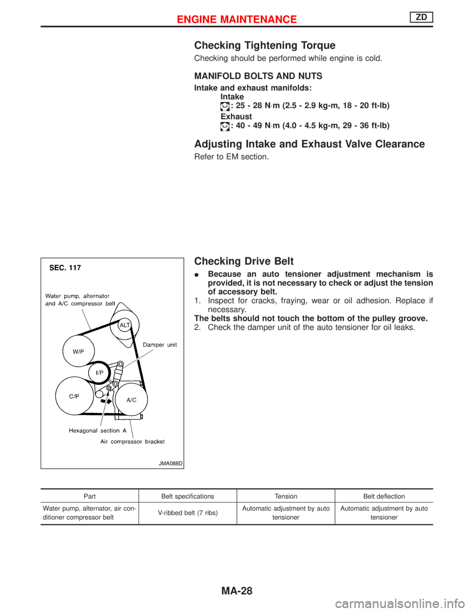
Checking Drive Belt
IBecause an auto tensioner adjustment mechanism is
provided, it is not necessary to check or adjust the tension
of accessory belt.
1. Inspect for cracks, fraying, wear or oil adhesion. Replace if
necessary.
The belts should not touch the bottom of the pulley groove.
2. Check the damper unit of the auto tensioner for oil leaks.
Part Belt specifications Tension Belt deflection
Water pump, alternator, air con-
ditioner compressor beltV-ribbed belt (7 ribs)Automatic adjustment by auto
tensionerAutomatic adjustment by auto
tensioner
JMA088D
ENGINE MAINTENANCEZD
MA-28
Page 1488 of 1767
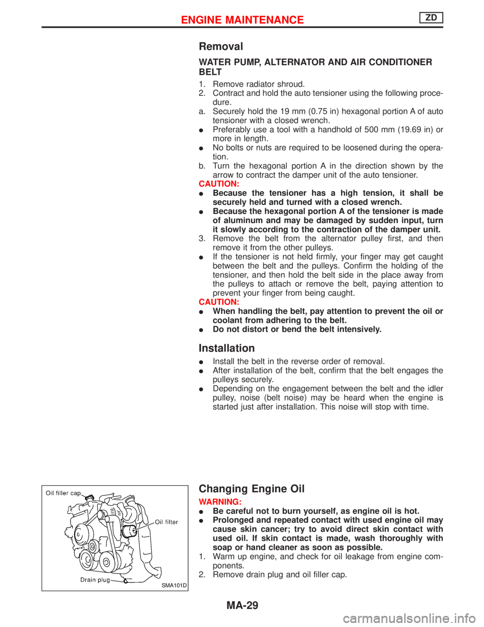
Removal
WATER PUMP, ALTERNATOR AND AIR CONDITIONER
BELT
1. Remove radiator shroud.
2. Contract and hold the auto tensioner using the following proce-
dure.
a. Securely hold the 19 mm (0.75 in) hexagonal portion A of auto
tensioner with a closed wrench.
IPreferably use a tool with a handhold of 500 mm (19.69 in) or
more in length.
INo bolts or nuts are required to be loosened during the opera-
tion.
b. Turn the hexagonal portion A in the direction shown by the
arrow to contract the damper unit of the auto tensioner.
CAUTION:
IBecause the tensioner has a high tension, it shall be
securely held and turned with a closed wrench.
IBecause the hexagonal portion A of the tensioner is made
of aluminum and may be damaged by sudden input, turn
it slowly according to the contraction of the damper unit.
3. Remove the belt from the alternator pulley first, and then
remove it from the other pulleys.
IIf the tensioner is not held firmly, your finger may get caught
between the belt and the pulleys. Confirm the holding of the
tensioner, and then hold the belt side in the place away from
the pulleys to attach or remove the belt, paying attention to
prevent your finger from being caught.
CAUTION:
IWhen handling the belt, pay attention to prevent the oil or
coolant from adhering to the belt.
IDo not distort or bend the belt intensively.
Installation
IInstall the belt in the reverse order of removal.
IAfter installation of the belt, confirm that the belt engages the
pulleys securely.
IDepending on the engagement between the belt and the idler
pulley, noise (belt noise) may be heard when the engine is
started just after installation. This noise will stop with time.
Changing Engine Oil
WARNING:
IBe careful not to burn yourself, as engine oil is hot.
IProlonged and repeated contact with used engine oil may
cause skin cancer; try to avoid direct skin contact with
used oil. If skin contact is made, wash thoroughly with
soap or hand cleaner as soon as possible.
1. Warm up engine, and check for oil leakage from engine com-
ponents.
2. Remove drain plug and oil filler cap.
SMA101D
ENGINE MAINTENANCEZD
MA-29