2002 NISSAN TERRANO water pump
[x] Cancel search: water pumpPage 1156 of 1767
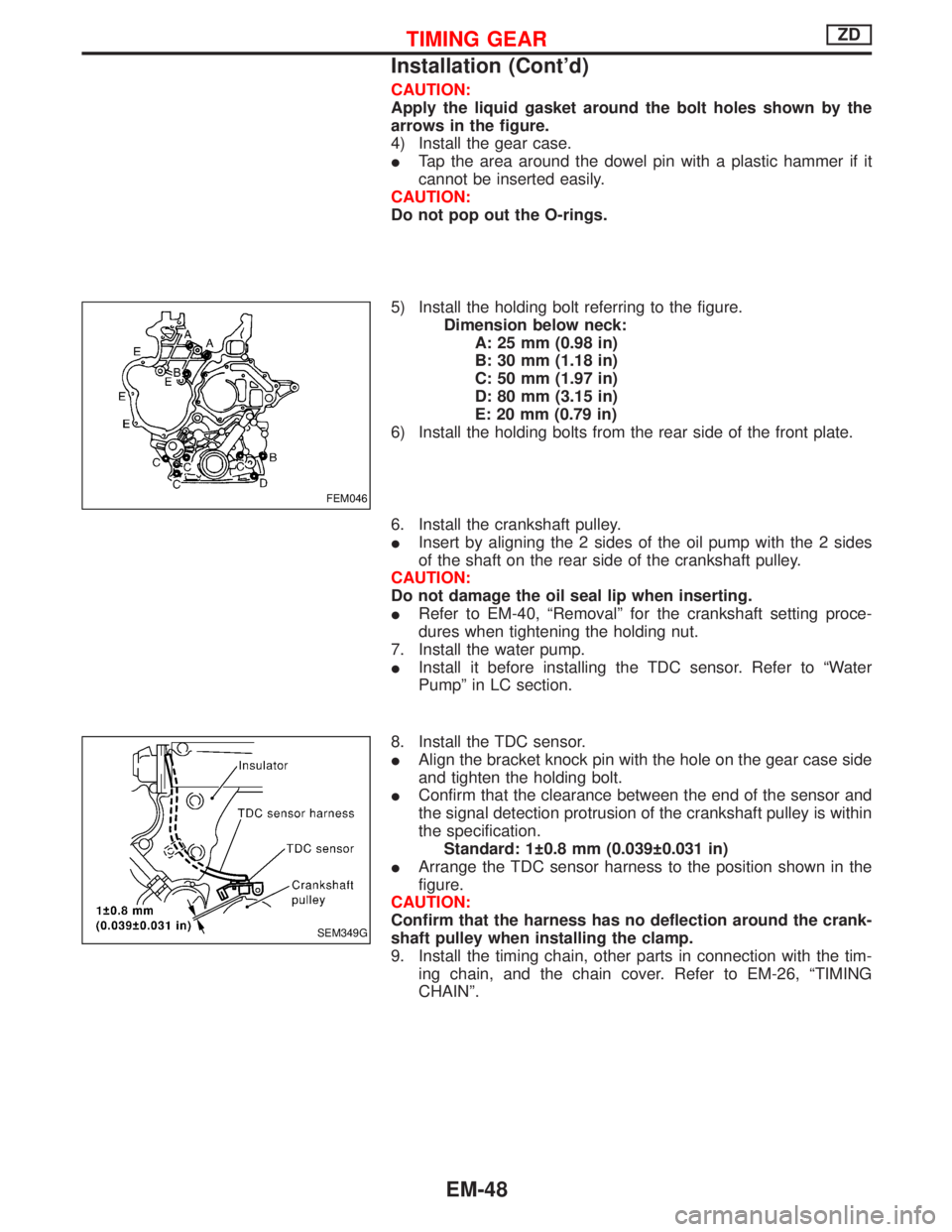
CAUTION:
Apply the liquid gasket around the bolt holes shown by the
arrows in the figure.
4) Install the gear case.
ITap the area around the dowel pin with a plastic hammer if it
cannot be inserted easily.
CAUTION:
Do not pop out the O-rings.
5) Install the holding bolt referring to the figure.
Dimension below neck:
A: 25 mm (0.98 in)
B: 30 mm (1.18 in)
C: 50 mm (1.97 in)
D: 80 mm (3.15 in)
E: 20 mm (0.79 in)
6) Install the holding bolts from the rear side of the front plate.
6. Install the crankshaft pulley.
IInsert by aligning the 2 sides of the oil pump with the 2 sides
of the shaft on the rear side of the crankshaft pulley.
CAUTION:
Do not damage the oil seal lip when inserting.
IRefer to EM-40, ªRemovalº for the crankshaft setting proce-
dures when tightening the holding nut.
7. Install the water pump.
IInstall it before installing the TDC sensor. Refer to ªWater
Pumpº in LC section.
8. Install the TDC sensor.
IAlign the bracket knock pin with the hole on the gear case side
and tighten the holding bolt.
IConfirm that the clearance between the end of the sensor and
the signal detection protrusion of the crankshaft pulley is within
the specification.
Standard: 1 0.8 mm (0.039 0.031 in)
IArrange the TDC sensor harness to the position shown in the
figure.
CAUTION:
Confirm that the harness has no deflection around the crank-
shaft pulley when installing the clamp.
9. Install the timing chain, other parts in connection with the tim-
ing chain, and the chain cover. Refer to EM-26, ªTIMING
CHAINº.
FEM046
SEM349G
TIMING GEARZD
Installation (Cont'd)
EM-48
Page 1160 of 1767
Removal and Installation
Removal
1. Remove the following. (Refer to corresponding chapter for
detailed auxiliary work.)
IDrain coolant
IRocker cover
IInjection tube
ISpill tube
IHigh pressure injection nozzle assembly
ITiming chain
ICamshaft
ICatalytic converter
ITurbocharger assembly
IExhaust manifold
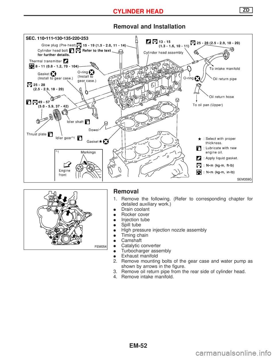
2. Remove mounting bolts of the gear case and water pump as
shown by arrows in the figure.
3. Remove oil return pipe from the rear side of cylinder head.
4. Remove intake manifold.
SEM359G
FEM054
CYLINDER HEADZD
EM-52
Page 1176 of 1767
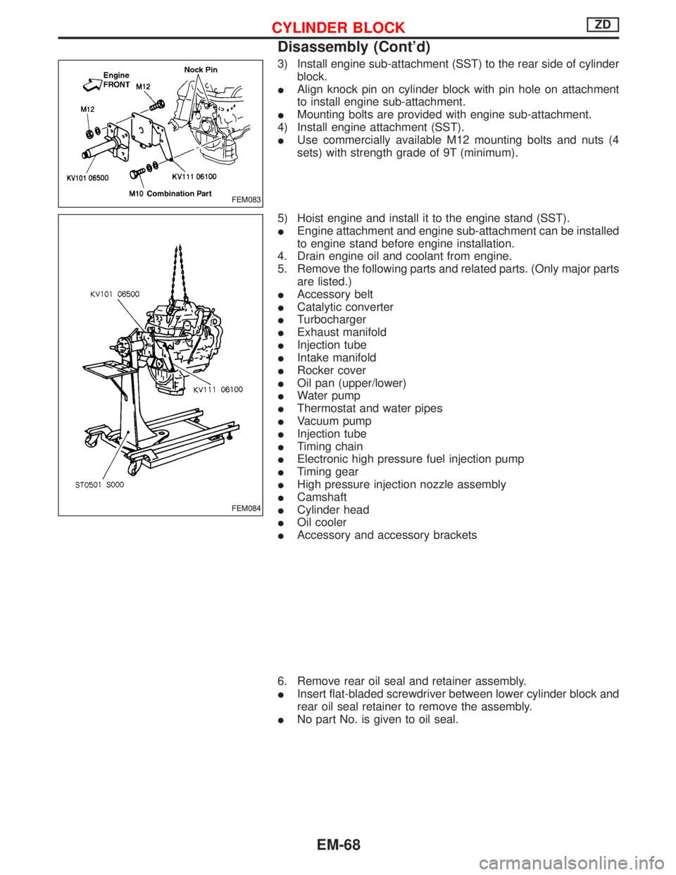
3) Install engine sub-attachment (SST) to the rear side of cylinder
block.
IAlign knock pin on cylinder block with pin hole on attachment
to install engine sub-attachment.
IMounting bolts are provided with engine sub-attachment.
4) Install engine attachment (SST).
IUse commercially available M12 mounting bolts and nuts (4
sets) with strength grade of 9T (minimum).
5) Hoist engine and install it to the engine stand (SST).
IEngine attachment and engine sub-attachment can be installed
to engine stand before engine installation.
4. Drain engine oil and coolant from engine.
5. Remove the following parts and related parts. (Only major parts
are listed.)
IAccessory belt
ICatalytic converter
ITurbocharger
IExhaust manifold
IInjection tube
IIntake manifold
IRocker cover
IOil pan (upper/lower)
IWater pump
IThermostat and water pipes
IVacuum pump
IInjection tube
ITiming chain
IElectronic high pressure fuel injection pump
ITiming gear
IHigh pressure injection nozzle assembly
ICamshaft
ICylinder head
IOil cooler
IAccessory and accessory brackets
6. Remove rear oil seal and retainer assembly.
IInsert flat-bladed screwdriver between lower cylinder block and
rear oil seal retainer to remove the assembly.
INo part No. is given to oil seal.
FEM083
FEM084
CYLINDER BLOCKZD
Disassembly (Cont'd)
EM-68
Page 1211 of 1767
Measurement of Compression Pressure
1. Warm up engine and switch off the ignition switch.
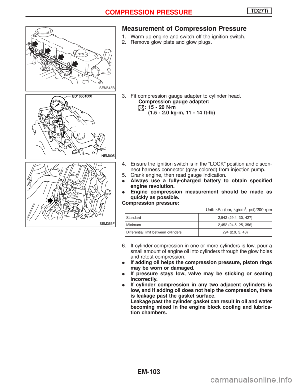
2. Remove glow plate and glow plugs.
3. Fit compression gauge adapter to cylinder head.
Compression gauge adapter:
:15-20N×m
(1.5 - 2.0 kg-m, 11 - 14 ft-lb)
4. Ensure the ignition switch is in the ªLOCKº position and discon-
nect harness connector (gray colored) from injection pump.
5. Crank engine, then read gauge indication.
IAlways use a fully-charged battery to obtain specified
engine revolution.
IEngine compression measurement should be made as
quickly as possible.
Compression pressure:
Unit: kPa (bar, kg/cm2, psi)/200 rpm
Standard 2,942 (29.4, 30, 427)
Minimum 2,452 (24.5, 25, 356)
Differential limit between cylinders 294 (2.9, 3, 43)
6. If cylinder compression in one or more cylinders is low, pour a
small amount of engine oil into cylinders through the glow holes
and retest compression.
IIf adding oil helps the compression pressure, piston rings
may be worn or damaged.
IIf pressure stays low, valve may be sticking or seating
incorrectly.
IIf cylinder compression in any two adjacent cylinders is
low, and if adding oil does not help the compression, there
is leakage past the gasket surface.
Leakage past the cylinder gasket can result in oil and water
becoming mixed in the engine block cooling and lubrica-
tion chambers.
SEM618B
NEM005
SEM355F
COMPRESSION PRESSURETD27Ti
EM-103
Page 1213 of 1767
Removal
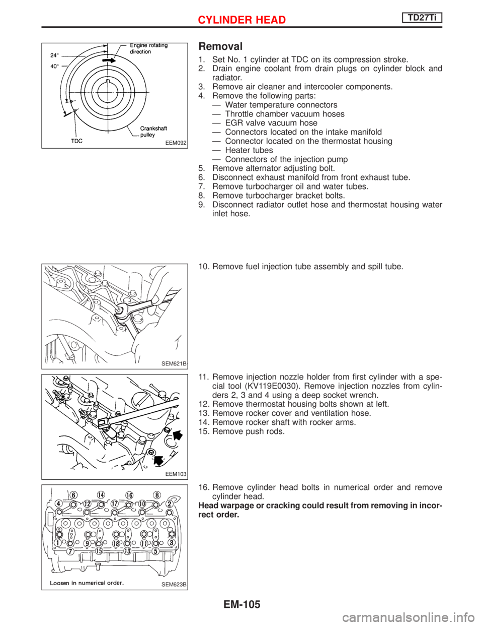
1. Set No. 1 cylinder at TDC on its compression stroke.
2. Drain engine coolant from drain plugs on cylinder block and
radiator.
3. Remove air cleaner and intercooler components.
4. Remove the following parts:
Ð Water temperature connectors
Ð Throttle chamber vacuum hoses
Ð EGR valve vacuum hose
Ð Connectors located on the intake manifold
Ð Connector located on the thermostat housing
Ð Heater tubes
Ð Connectors of the injection pump
5. Remove alternator adjusting bolt.
6. Disconnect exhaust manifold from front exhaust tube.
7. Remove turbocharger oil and water tubes.
8. Remove turbocharger bracket bolts.
9. Disconnect radiator outlet hose and thermostat housing water
inlet hose.
10. Remove fuel injection tube assembly and spill tube.
11. Remove injection nozzle holder from first cylinder with a spe-
cial tool (KV119E0030). Remove injection nozzles from cylin-
ders 2, 3 and 4 using a deep socket wrench.
12. Remove thermostat housing bolts shown at left.
13. Remove rocker cover and ventilation hose.
14. Remove rocker shaft with rocker arms.
15. Remove push rods.
16. Remove cylinder head bolts in numerical order and remove
cylinder head.
Head warpage or cracking could result from removing in incor-
rect order.
EEM092
SEM621B
EEM103
SEM623B
CYLINDER HEADTD27Ti
EM-105
Page 1233 of 1767
Disassembly
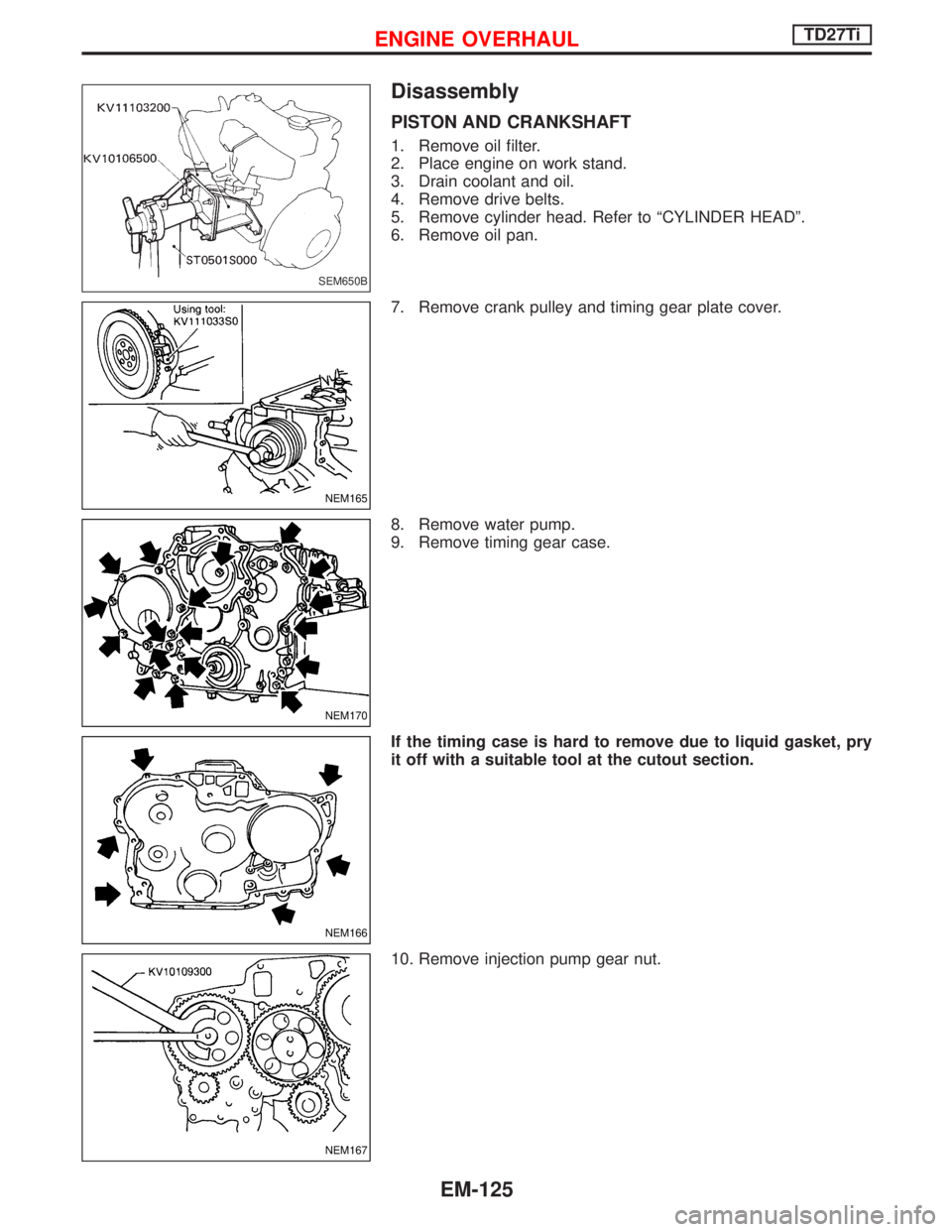
PISTON AND CRANKSHAFT
1. Remove oil filter.
2. Place engine on work stand.
3. Drain coolant and oil.
4. Remove drive belts.
5. Remove cylinder head. Refer to ªCYLINDER HEADº.
6. Remove oil pan.
7. Remove crank pulley and timing gear plate cover.
8. Remove water pump.
9. Remove timing gear case.
If the timing case is hard to remove due to liquid gasket, pry
it off with a suitable tool at the cutout section.
10. Remove injection pump gear nut.
SEM650B
NEM165
NEM170
NEM166
NEM167
ENGINE OVERHAULTD27Ti
EM-125
Page 1424 of 1767
TAIL/L - Wiring diagram ..................................EL-45
TCM circuit diagram ..........................................AT-7
TCM inspection table ......................................AT-46
TDC Pulse Signal .........................................EC-168
Temperature control cable and linkage
adjustment ..................................................HA-63
THEFT - Wiring diagram...............................EL-214
Theft warning system ...........EL-209, 210, 213, 230
Thermo control amp .................................HA-51, 61
Thermostat................................................LC-12, 31
Third (3rd) seat ...............................................BT-39
THLCNT - Wiring diagram ...........................EC-435
Three way catalyst precautions.........................GI-5
Throttle control solenoid valve .....................EC-435
Throttle position switch ...................................AT-60
Tie-rod .......................................................ST-19, 21
Tie-rod ball joints.............................................ST-20
Tightening torque of standard bolts.................GI-38
Time control system .....................EL-180, 182, 184
Timing chain ...................................................EM-26
Timing gear ....................................................EM-38
Tire rotation ....................................................MA-43
Tooth contact diff. .....................................PD-27, 52
Torque convertor clutch solenoid valve ..AT-72, 141
Torsion bar spring .......................................FA-4, 30
Tow truck towing ..............................................GI-33
Towing point.....................................................GI-34
Transaxle fluid replacement.....................MA-36, 37
Transfer case ..............................................TF-9, 12
Transfer fluid replacement (Part time
4WD model) .........................................MA-36, 37
Transfer oil replacement ..........................MA-36, 38
Transmission case (M/T)..........................MT-10, 14
TRANSMT - Wiring diagram ...........................EL-80
Tread-FR&RR (Dimensions)............................GI-25
Trim...............................................BT-18, 19, 20, 21
Trunk room trim...............................................BT-47
Turbocharger ..................................................EM-14
Turbocharger charge air cooler......................EM-11
Turbocharger precautions..................................GI-5
TURN - Wiring diagram ..................................EL-56
Turn signal lamp .......................................EL-55, 56
U
Under body .....................................................BT-53
Upper link (front susp.) ...................................FA-33
V
Vacuum hose (brake system) ........................BR-19Vacuum hose drawing (Engine
control)................................................EC-18, 304
Vacuum pump .............................EM-24, BR-23, 25
Valve clearance..............................................EM-35
Valve clearance adjustment.....................MA-20, 28
Valve guide ....................................................EM-59
Valve lifter ......................................................EM-32
Valve seat ......................................................EM-60
Valve spring ...................................................EM-61
Variable nozzle turbocharger control
solenoid valve ...........................................EC-281
Vehicle identification number...........................GI-29
Vehicle speed sensor (VSS) ..................EC-99, 397
Ventilator door control rod adjustment ...........HA-61
Viscosity number (SAE)...........................MA-17, 18
VNT - Wiring diagram ..................................EC-283
VSS - Wiring diagram ..................................EC-101
W
WARN - Wiring diagram ...........................EL-82, 93
Warning chime ..........................................EL-81, 93
Warning lamps ..........................................EL-81, 82
Washer, front ...................................................EL-94
Washer, rear....................................................EL-96
Water cock control rod adjustment ................HA-63
Water pump ..............................................LC-11, 29
Water temperature gauge ...............................EL-72
Weatherstrip - See Exterior ............................BT-21
Wheel alignment (front) ....................................FA-8
Wheel balance ...............................................MA-43
Wheel bearing (front axle) ................................FA-6
Wheel bearing (rear) ..................................RA-5, 16
Wheel hub (front) ........................................FA-4, 18
Wheel sensors (ABS)...............................BR-38, 42
Wheel size .......................................................GI-31
WINDOW - Wiring diagram ..........................EL-134
Window, back door .........................................BT-47
Window, door ..................................................BT-42
Window, rear side .....................................BT-42, 43
Window, side - See Rear side window ...........BT-43
Windshield.......................................................BT-42
WIP/R - Wiring diagram ..................................EL-96
WIPER - Wiring diagram ........................EL-94, 100
Wiper and washer.....................................EL-94, 98
Wiper, front......................................................EL-94
Wiper, rear ......................................................EL-96
Wiring Diagram (Cell code) list .....................EL-291
ALPHABETICAL INDEX
IDX-7
Page 1426 of 1767
ENGINE LUBRICATION &
COOLING SYSTEMS
SECTION
LC
CONTENTS
ZD
PRECAUTIONS AND PREPARATION............................2
Liquid Gasket Application Procedure ..........................2
Special Service Tools ..................................................2
ENGINE LUBRICATION SYSTEM..................................3
Lubricating Circuit ........................................................3
Oil Pressure Check......................................................4
Oil Pump ......................................................................5
Oil Jet...........................................................................7
Oil Cooler .....................................................................8
ENGINE COOLING SYSTEM..........................................9
Cooling Circuit .............................................................9
System Check............................................................10
Water Pump ............................................................... 11
Thermostat .................................................................12
Water Outlet ...............................................................13
Radiator .....................................................................14
Cooling Fan (Crankshaft driven) ...............................15
EGR Cooler ...............................................................16
SERVICE DATA AND SPECIFICATIONS (SDS)..........17
Engine Lubrication System ........................................17
Engine Cooling System .............................................17TD27TiPREPARATION..............................................................18
PRECAUTION................................................................19
ENGINE LUBRICATION SYSTEM................................20
Lubrication Circuit ......................................................20
Oil Pressure Check....................................................21
Oil Pump ....................................................................22
Oil Filter Bracket ........................................................24
Oil Cooler ...................................................................25
Oil Jet.........................................................................26
ENGINE COOLING SYSTEM........................................27
Cooling Circuit ...........................................................27
System Inspection .....................................................28
Water Pump ...............................................................29
Thermostat .................................................................31
Radiator .....................................................................32
Cooling Fan ...............................................................33
SERVICE DATA AND SPECIFICATIONS (SDS)..........34
Engine Lubrication System ........................................34
Engine Cooling System .............................................34