Page 838 of 1767
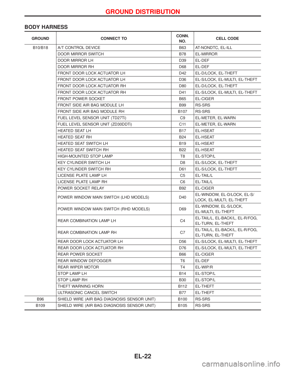
BODY HARNESS
GROUND CONNECT TOCONN.
NO.CELL CODE
B10/B18 A/T CONTROL DEVICE B63 AT-NONDTC, EL-ILL
DOOR MIRROR SWITCH B78 EL-MIRROR
DOOR MIRROR LH D39 EL-DEF
DOOR MIRROR RH D68 EL-DEF
FRONT DOOR LOCK ACTUATOR LH D42 EL-D/LOCK, EL-THEFT
FRONT DOOR LOCK ACTUATOR LH D36 EL-S/LOCK, EL-MULTI, EL-THEFT
FRONT DOOR LOCK ACTUATOR RH D80 EL-D/LOCK, EL-THEFT
FRONT DOOR LOCK ACTUATOR RH D41 EL-S/LOCK, EL-MULTI, EL-THEFT
FRONT POWER SOCKET B65 EL-CIGER
FRONT SIDE AIR BAG MODULE LH B99 RS-SRS
FRONT SIDE AIR BAG MODULE RH B107 RS-SRS
FUEL LEVEL SENSOR UNIT (TD27Ti) C9 EL-METER, EL-WARN
FUEL LEVEL SENSOR UNIT (ZD30DDTi) C11 EL-METER, EL-WARN
HEATED SEAT LH B17 EL-HSEAT
HEATED SEAT RH B24 EL-HSEAT
HEATED SEAT SWITCH LH B19 EL-HSEAT
HEATED SEAT SWITCH RH B22 EL-HSEAT
HIGH-MOUNTED STOP LAMP T8 EL-STOP/L
KEY CYLINDER SWITCH LH D8 EL-S/LOCK, EL-THEFT
KEY CYLINDER SWITCH RH D61 EL-S/LOCK, EL-THEFT
LICENSE PLATE LAMP LH C5 EL-TAIL/L
LICENSE PLATE LAMP RH C6 EL-TAIL/L
POWER SOCKET RELAY B92 EL-CIGER
POWER WINDOW MAIN SWITCH (LHD MODELS) D40EL-WINDOW, EL-D/LOCK, EL-S/
LOCK, EL-MULTI, EL-THEFT
POWER WINDOW MAIN SWITCH (RHD MODELS) D69EL-WINDOW, EL-S/LOCK,
EL-MULTI, EL-THEFT
REAR COMBINATION LAMP LH C4EL-TAIL/L, EL-BACK/L, EL-R/FOG,
EL-TURN, EL-THEFT
REAR COMBINATION LAMP RH C7EL-TAIL/L, EL-BACK/L, EL-R/FOG,
EL-TURN, EL-THEFT
REAR DOOR LOCK ACTUATOR LH D56 EL-S/LOCK, EL-MULTI, EL-THEFT
REAR DOOR LOCK ACTUATOR RH D76 EL-S/LOCK, EL-MULTI, EL-THEFT
REAR POWER SOCKET B66 EL-CIGER
REAR WINDOW DEFOGGER T6 EL-DEF
REAR WIPER MOTOR T4 EL-WIP/R
STOP LAMP LH B14 EL-STOP/L
STOP LAMP RH B30 EL-STOP/L
THEFT WARNING HORN B112 EL-THEFT
ULTRASONIC CANCEL SWITCH B77 EL-THEFT
B96 SHIELD WIRE (AIR BAG DIAGNOSIS SENSOR UNIT) B100 RS-SRS
B109 SHIELD WIRE (AIR BAG DIAGNOSIS SENSOR UNIT) B105 RS-SRS
GROUND DISTRIBUTION
EL-22
Page 894 of 1767
Components Inspection
AMBIENT TEMPERATURE SENSOR
Intake air temperature
ÉC (ÉF)Resistance
kW
þ20 (þ4) 10.5 - 10.8
0 (32) 6.1 - 6.24
20 (68) 3.0 - 3.1
50 (122) 0.85 - 1.04
SEF012P
METER AND GAUGES
EL-78
Page 895 of 1767
Trouble Diagnoses
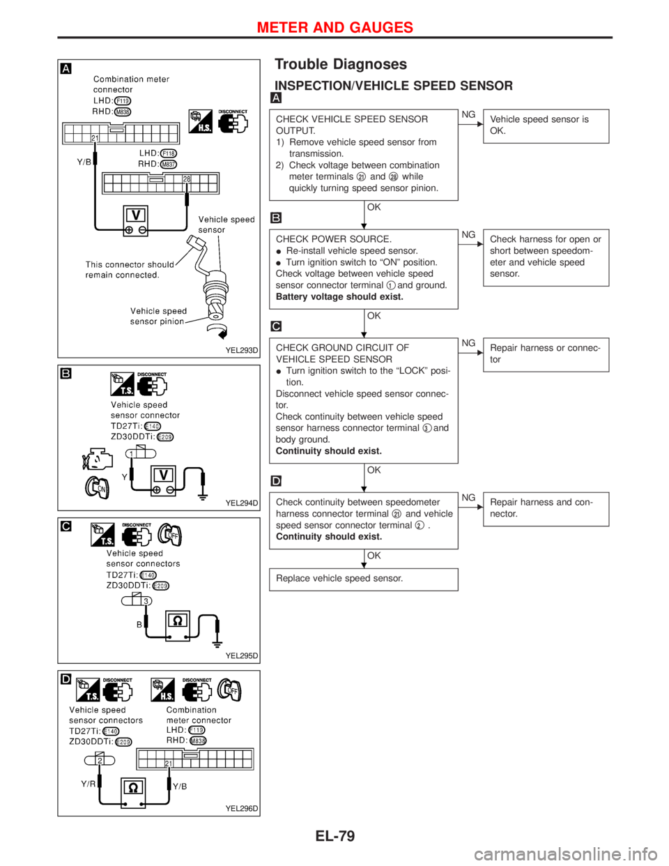
INSPECTION/VEHICLE SPEED SENSOR
CHECK VEHICLE SPEED SENSOR
OUTPUT.
1) Remove vehicle speed sensor from
transmission.
2) Check voltage between combination
meter terminalsq
21andq28while
quickly turning speed sensor pinion.
OK
ENG
Vehicle speed sensor is
OK.
CHECK POWER SOURCE.
IRe-install vehicle speed sensor.
ITurn ignition switch to ªONº position.
Check voltage between vehicle speed
sensor connector terminalq
1and ground.
Battery voltage should exist.
OK
ENG
Check harness for open or
short between speedom-
eter and vehicle speed
sensor.
CHECK GROUND CIRCUIT OF
VEHICLE SPEED SENSOR
ITurn ignition switch to the ªLOCKº posi-
tion.
Disconnect vehicle speed sensor connec-
tor.
Check continuity between vehicle speed
sensor harness connector terminalq
3and
body ground.
Continuity should exist.
OK
ENG
Repair harness or connec-
tor
Check continuity between speedometer
harness connector terminalq
21and vehicle
speed sensor connector terminalq
2.
Continuity should exist.
OK
ENG
Repair harness and con-
nector.
Replace vehicle speed sensor.
YEL293D
YEL294D
YEL295D
YEL296D
H
H
H
H
METER AND GAUGES
EL-79
Page 975 of 1767
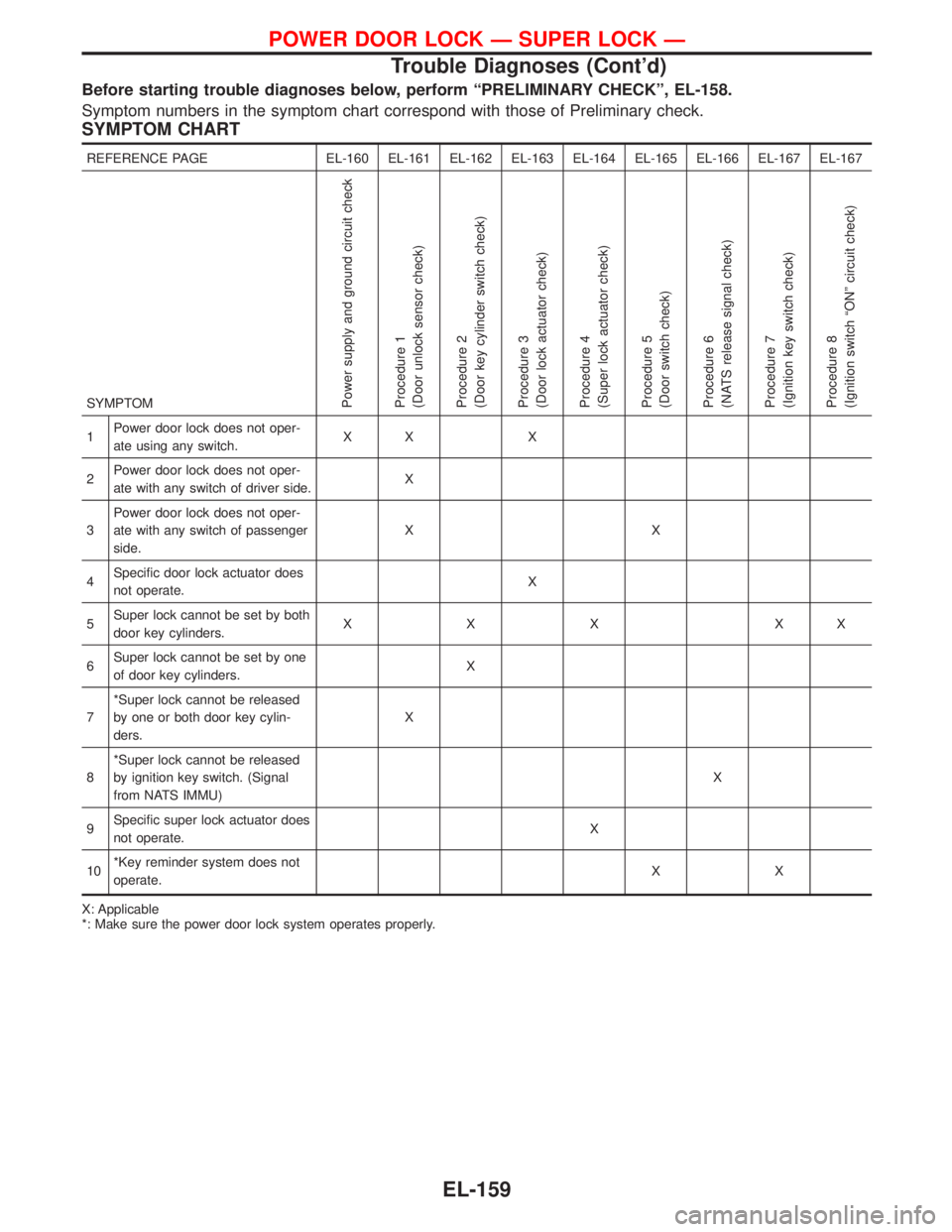
Before starting trouble diagnoses below, perform ªPRELIMINARY CHECKº, EL-158.
Symptom numbers in the symptom chart correspond with those of Preliminary check.
SYMPTOM CHART
REFERENCE PAGE EL-160 EL-161 EL-162 EL-163 EL-164 EL-165 EL-166 EL-167 EL-167
SYMPTOM
Power supply and ground circuit check
Procedure 1
(Door unlock sensor check)
Procedure 2
(Door key cylinder switch check)
Procedure 3
(Door lock actuator check)
Procedure 4
(Super lock actuator check)
Procedure 5
(Door switch check)
Procedure 6
(NATS release signal check)
Procedure 7
(Ignition key switch check)
Procedure 8
(Ignition switch ªONº circuit check)
1Power door lock does not oper-
ate using any switch.XX X
2Power door lock does not oper-
ate with any switch of driver side.X
3Power door lock does not oper-
ate with any switch of passenger
side.XX
4Specific door lock actuator does
not operate.X
5Super lock cannot be set by both
door key cylinders.XXX XX
6Super lock cannot be set by one
of door key cylinders.X
7*Super lock cannot be released
by one or both door key cylin-
ders.X
8*Super lock cannot be released
by ignition key switch. (Signal
from NATS IMMU)X
9Specific super lock actuator does
not operate.X
10*Key reminder system does not
operate.XX
X: Applicable
*: Make sure the power door lock system operates properly.
POWER DOOR LOCK Ð SUPER LOCK Ð
Trouble Diagnoses (Cont'd)
EL-159
Page 977 of 1767
DIAGNOSTIC PROCEDURE 1
(Door unlock sensor check)
CHECK DOOR UNLOCK SENSOR
INPUT SIGNAL.
Check voltage between time control unit
connector terminals
U35orU36and
ground.
NG
EOK
Door unlock sensor is OK.
CHECK DOOR UNLOCK SENSOR.
1) Disconnect door unlock sensor con-
nector.
2) Check continuity between door unlock
sensor terminals.
OK
ENG
Replace door lock actuator
assembly.
Check the following:
IDoor unlock sensor ground circuit.
IHarness for open or short-circuit
between control unit and door unlock
sensor
Terminals
Condi-
tionVoltage
[V]
!@
Driver
side
U35GroundLockedApprox.
2
(Approx.
20 sec.)
Unlocked 0
Pas-
senger
side
U36GroundLockedApprox.
12
(Approx.
20 sec.)
Unlocked 0
Terminals Condition Continuity
q
2-q5Locked No
Unlocked Yes
YEL301D
YEL302D
H
H
POWER DOOR LOCK Ð SUPER LOCK Ð
Trouble Diagnoses (Cont'd)
EL-161
Page 993 of 1767
Trouble Diagnoses
If doors can not be unlocked by remote controller operation then the following procedure is required.
A) Unlock the vehicle by a mechanical key in the drivers door key cylinder.
Note: this may cause the alarm to sound.
B) Put the key in ignition, turn to ON position for at least five seconds. Assuming the ignition key contains a
valid transponder then a signal will be generated by the immobilizer which will disarm the alarm and allow
key learn mode to be entered.
C) Turn ignition OFF and wait for ten seconds.
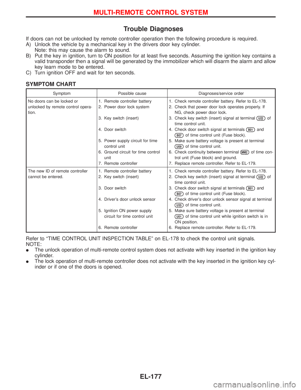
SYMPTOM CHART
Symptom Possible cause Diagnoses/service order
No doors can be locked or
unlocked by remote control opera-
tion.1. Remote controller battery
2. Power door lock system
3. Key switch (insert)
4. Door switch
5. Power supply circuit for time
control unit
6. Ground circuit for time control
unit
7. Remote controller1. Check remote controller battery. Refer to EL-178.
2. Check that power door lock operates properly. If
NG, check power door lock.
3. Check key switch (insert) signal at terminal
U22of
time control unit.
4. Check door switch signal at terminals
B01and
B07of time control unit (Fuse block).
5. Make sure battery voltage is present at terminal
U09of time control unit.
6. Check continuity between terminal
MM2of time con-
trol unit (Fuse block) and ground.
7. Replace remote controller. Refer to EL-179.
The new ID of remote controller
cannot be entered.1. Remote controller battery
2. Key switch (insert)
3. Door switch
4. Driver's door unlock sensor
5. Ignition ON power supply
circuit for time control unit
6. Remote controller1. Check remote controller battery. Refer to EL-178.
2. Check key switch (insert) signal at terminal
U22of
time control unit.
3. Check door switch signal at terminals
B01and
B07of time control unit (Fuse block).
4. Check driver's door unlock sensor signal at terminal
U35of time control unit.
5. Make sure battery voltage is present at terminal
U01of time control unit while ignition switch is in
ON position.
6. Replace remote controller. Refer to EL-179.
Refer to ªTIME CONTROL UNIT INSPECTION TABLEº on EL-178 to check the control unit signals.
NOTE:
IThe unlock operation of multi-remote control system does not activate with key inserted in the ignition key
cylinder.
IThe lock operation of multi-remote controller does not activate with the key inserted in the ignition key cyl-
inder or if one of the doors is opened.
MULTI-REMOTE CONTROL SYSTEM
EL-177
Page 994 of 1767
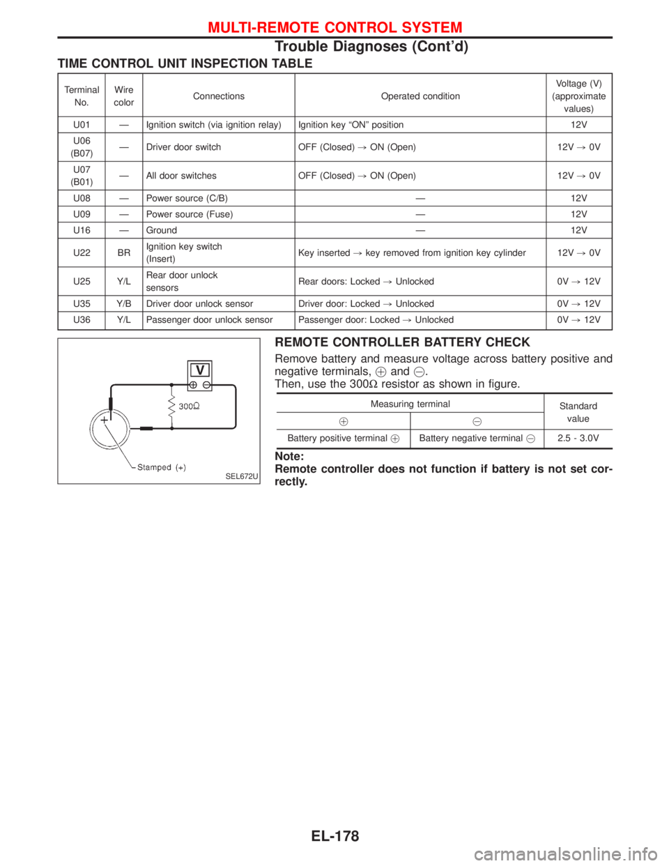
TIME CONTROL UNIT INSPECTION TABLE
Terminal
No.Wire
colorConnections Operated conditionVoltage (V)
(approximate
values)
U01 Ð Ignition switch (via ignition relay) Ignition key ªONº position 12V
U06
(B07)Ð Driver door switch OFF (Closed),ON (Open) 12V,0V
U07
(B01)Ð All door switches OFF (Closed),ON (Open) 12V,0V
U08 Ð Power source (C/B) Ð 12V
U09 Ð Power source (Fuse) Ð 12V
U16 Ð Ground Ð 12V
U22 BRIgnition key switch
(Insert)Key inserted,key removed from ignition key cylinder 12V,0V
U25 Y/LRear door unlock
sensorsRear doors: Locked,Unlocked 0V,12V
U35 Y/B Driver door unlock sensor Driver door: Locked,Unlocked 0V,12V
U36 Y/L Passenger door unlock sensor Passenger door: Locked,Unlocked 0V,12V
REMOTE CONTROLLER BATTERY CHECK
Remove battery and measure voltage across battery positive and
negative terminals,!and@.
Then, use the 300Wresistor as shown in figure.
Measuring terminal
Standard
value
!@
Battery positive terminal!Battery negative [email protected] - 3.0V
Note:
Remote controller does not function if battery is not set cor-
rectly.
SEL672U
MULTI-REMOTE CONTROL SYSTEM
Trouble Diagnoses (Cont'd)
EL-178
Page 997 of 1767
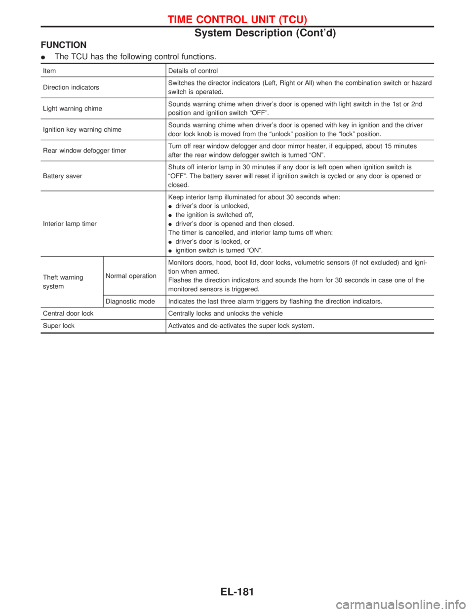
FUNCTION
IThe TCU has the following control functions.
Item Details of control
Direction indicatorsSwitches the director indicators (Left, Right or All) when the combination switch or hazard
switch is operated.
Light warning chimeSounds warning chime when driver's door is opened with light switch in the 1st or 2nd
position and ignition switch ªOFFº.
Ignition key warning chimeSounds warning chime when driver's door is opened with key in ignition and the driver
door lock knob is moved from the ªunlockº position to the ªlockº position.
Rear window defogger timerTurn off rear window defogger and door mirror heater, if equipped, about 15 minutes
after the rear window defogger switch is turned ªONº.
Battery saverShuts off interior lamp in 30 minutes if any door is left open when ignition switch is
ªOFFº. The battery saver will reset if ignition switch is cycled or any door is opened or
closed.
Interior lamp timerKeep interior lamp illuminated for about 30 seconds when:
Idriver's door is unlocked,
Ithe ignition is switched off,
Idriver's door is opened and then closed.
The timer is cancelled, and interior lamp turns off when:
Idriver's door is locked, or
Iignition switch is turned ªONº.
Theft warning
systemNormal operationMonitors doors, hood, boot lid, door locks, volumetric sensors (if not excluded) and igni-
tion when armed.
Flashes the direction indicators and sounds the horn for 30 seconds in case one of the
monitored sensors is triggered.
Diagnostic mode Indicates the last three alarm triggers by flashing the direction indicators.
Central door lock Centrally locks and unlocks the vehicle
Super lock Activates and de-activates the super lock system.
TIME CONTROL UNIT (TCU)
System Description (Cont'd)
EL-181