Page 1139 of 1767

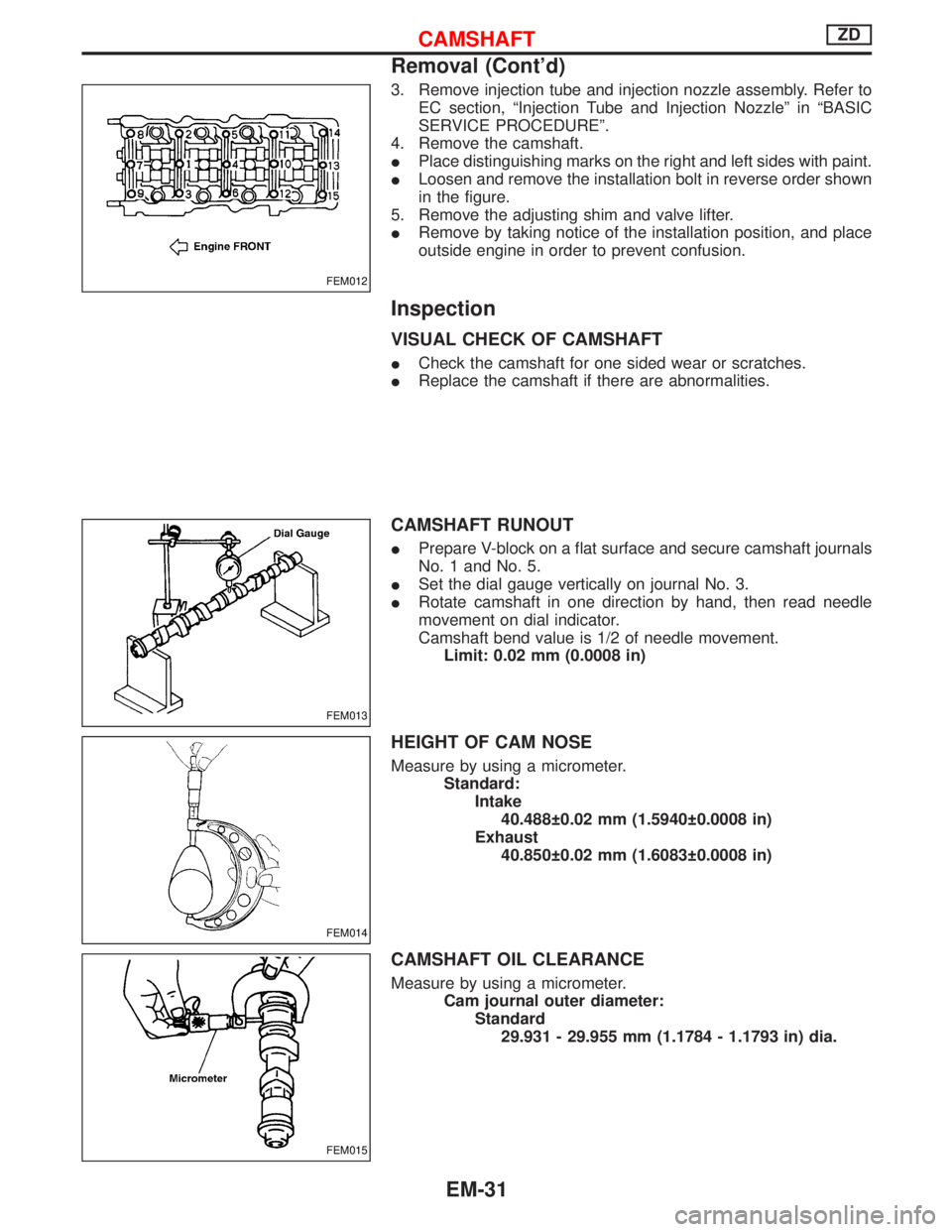
3. Remove injection tube and injection nozzle assembly. Refer to
EC section, ªInjection Tube and Injection Nozzleº in ªBASIC
SERVICE PROCEDUREº.
4. Remove the camshaft.
IPlace distinguishing marks on the right and left sides with paint.
ILoosen and remove the installation bolt in reverse order shown
in the figure.
5. Remove the adjusting shim and valve lifter.
IRemove by taking notice of the installation position, and place
outside engine in order to prevent confusion.
Inspection
VISUAL CHECK OF CAMSHAFT
ICheck the camshaft for one sided wear or scratches.
IReplace the camshaft if there are abnormalities.
CAMSHAFT RUNOUT
IPrepare V-block on a flat surface and secure camshaft journals
No. 1 and No. 5.
ISet the dial gauge vertically on journal No. 3.
IRotate camshaft in one direction by hand, then read needle
movement on dial indicator.
Camshaft bend value is 1/2 of needle movement.
Limit: 0.02 mm (0.0008 in)
HEIGHT OF CAM NOSE
Measure by using a micrometer.
Standard:
Intake
40.488 0.02 mm (1.5940 0.0008 in)
Exhaust
40.850 0.02 mm (1.6083 0.0008 in)
CAMSHAFT OIL CLEARANCE
Measure by using a micrometer.
Cam journal outer diameter:
Standard
29.931 - 29.955 mm (1.1784 - 1.1793 in) dia.
FEM012
FEM013
FEM014
FEM015
CAMSHAFTZD
Removal (Cont'd)
EM-31
Page 1197 of 1767
Camshaft and Camshaft Bearing
Unit: mm (in)
Standard Limit
Camshaft journal to bearing clearance 0.045 - 0.090 (0.0018 - 0.0035) 0.09 (0.0035)
Inner diameter of camshaft bearing 30.000 - 30.021 (1.1811 - 1.1819) Ð
Outer diameter of camshaft journal 29.931 - 29.955 (1.1784 - 1.1793) Ð
Camshaft runout [TIR*] Ð 0.02 (0.0008)
Camshaft sprocket runout [TIR*] Less than 0.15 (0.0059) Ð
Camshaft end play 0.065 - 0.169 (0.0026 - 0.0067) 0.2 (0.008)
*: Total indicator reading
EM671
Cam height ªAºIntake 40.468 - 40.508 (1.5932 - 1.5948)
Exhaust 40.830 - 40.870 (1.6075 - 1.6091)
Wear limit of cam height0.15 (0.0059)
Valve timing
SEM372G
Unit: degree
abcde
234 220 10 34 50
SERVICE DATA AND SPECIFICATIONS (SDS)ZD
EM-89
Page 1200 of 1767
Crankshaft
Unit: mm (in)
Main journal dia. ªDmº70.907 - 70.920 (2.7916 - 2.7921)
Pin journal dia. ªDpº Grade No. 0 56.913 - 56.926 (2.2407 - 2.2412)
Center distance ªrº50.95 - 51.05 (2.0059 - 2.0098)
Out-of-round (X þ Y) Standard Less than 0.01 (0.0004)
Taper (A þ B) Standard Less than 0.01 (0.0004)
Runout [TIR*]Standard Less than 0.01 (0.0004)
Limit Less than 0.03 (0.0012)
Free end playStandard 0.055 - 0.140 (0.0022 - 0.0055)
Limit 0.25 (0.0098)
SEM645EM715
*: Total indicator reading
Available Main Bearing
UNDERSIZE
FEM127
Size Thickness ªTº mm (in) Width ªWº mm (in) Main journal diameter ªDmº
Standard 2.005 - 2.013 (0.0789 - 0.0793)
25.74 - 26.00 (1.0134 - 1.0236)Grind so that bearing clearance is
the specified value. US 025 2.130 - 2.138 (0.0839 - 0.0842)
US 050 2.255 - 2.263 (0.0888 - 0.0891)
US 075 2.380 - 2.388 (0.0937 - 0.0940)
US 100 2.505 - 2.513 (0.0986 - 0.0989)
SERVICE DATA AND SPECIFICATIONS (SDS)ZD
EM-92
Page 1202 of 1767
Miscellaneous Components
Unit: mm (in)
Flywheel runout [TIR]*Less than 0.15 (0.0059)
Drive plate runout [TIR]*Less than 0.1 (0.0039)
*: Total indicator reading
BEARING CLEARANCE
Unit: mm (in)
Main bearing clearance Standard 0.035 - 0.083 (0.0014 - 0.0033)
Connecting rod bearing clearance Standard 0.035 - 0.077 (0.0014 - 0.0030)
SERVICE DATA AND SPECIFICATIONS (SDS)ZD
EM-94
Page 1255 of 1767

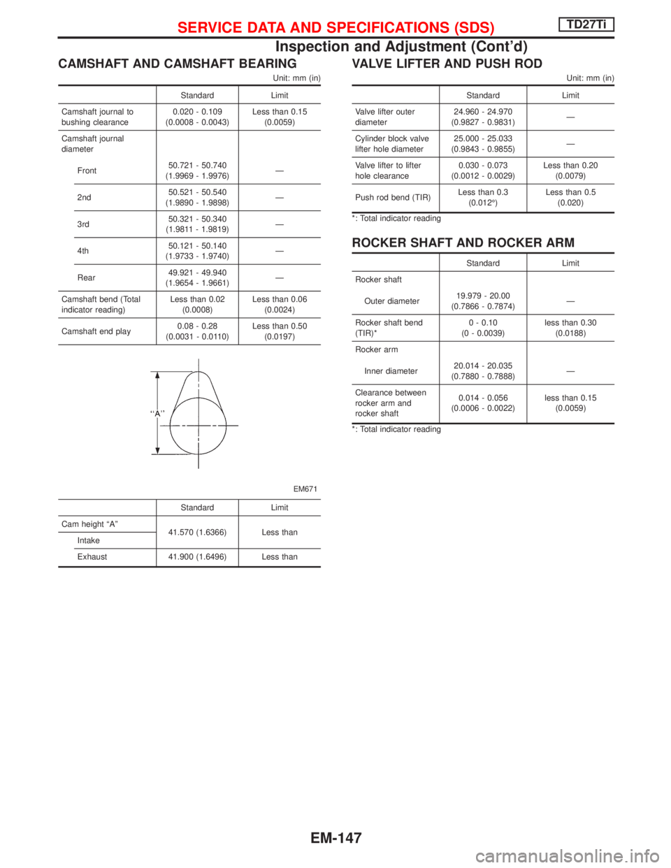
CAMSHAFT AND CAMSHAFT BEARING
Unit: mm (in)
Standard Limit
Camshaft journal to
bushing clearance0.020 - 0.109
(0.0008 - 0.0043)Less than 0.15
(0.0059)
Camshaft journal
diameter
Front50.721 - 50.740
(1.9969 - 1.9976)Ð
2nd50.521 - 50.540
(1.9890 - 1.9898)Ð
3rd50.321 - 50.340
(1.9811 - 1.9819)Ð
4th50.121 - 50.140
(1.9733 - 1.9740)Ð
Rear49.921 - 49.940
(1.9654 - 1.9661)Ð
Camshaft bend (Total
indicator reading)Less than 0.02
(0.0008)Less than 0.06
(0.0024)
Camshaft end play0.08 - 0.28
(0.0031 - 0.0110)Less than 0.50
(0.0197)
EM671
Standard Limit
Cam height ªAº
41.570 (1.6366) Less than
Intake
Exhaust 41.900 (1.6496) Less than
VALVE LIFTER AND PUSH ROD
Unit: mm (in)
Standard Limit
Valve lifter outer
diameter24.960 - 24.970
(0.9827 - 0.9831)Ð
Cylinder block valve
lifter hole diameter25.000 - 25.033
(0.9843 - 0.9855)Ð
Valve lifter to lifter
hole clearance0.030 - 0.073
(0.0012 - 0.0029)Less than 0.20
(0.0079)
Push rod bend (TIR)Less than 0.3
(0.012É)Less than 0.5
(0.020)
*: Total indicator reading
ROCKER SHAFT AND ROCKER ARM
Standard Limit
Rocker shaft
Outer diameter19.979 - 20.00
(0.7866 - 0.7874)Ð
Rocker shaft bend
(TIR)*0 - 0.10
(0 - 0.0039)less than 0.30
(0.0188)
Rocker arm
Inner diameter20.014 - 20.035
(0.7880 - 0.7888)Ð
Clearance between
rocker arm and
rocker shaft0.014 - 0.056
(0.0006 - 0.0022)less than 0.15
(0.0059)
*: Total indicator reading
SERVICE DATA AND SPECIFICATIONS (SDS)TD27Ti
Inspection and Adjustment (Cont'd)
EM-147
Page 1258 of 1767
AVAILABLE THRUST WASHER
Unit: mm (in)
Thrust washer thickness
Standard 2.275 - 2.325 (0.0896 - 0.0915)
Oversize
0.20 (0.0079) 2.475 - 2.525 (0.0974 - 0.0994)
0.40 (0.0157) 2.675 - 2.725 (0.1053 - 0.1073)
MISCELLANEOUS COMPONENTS
Unit: mm (in)
Gear train
Backlash of each gear
Standard 0.07 - 0.11 (0.0028 - 0.0043)
Limit 0.20 (0.0079)
Flywheel
Runout (Total indicator
reading)Less than 0.15 (0.0059)
Front plate
Warpage limit 0.2 (0.008)
Cylinder head
Head surface distorsion
Standard Less than 0.07 (0.0028)
Limit 0.2 (0.008)
Minimum height 89.7 (3.532)
SERVICE DATA AND SPECIFICATIONS (SDS)TD27Ti
Inspection and Adjustment (Cont'd)
EM-150
Page 1319 of 1767

insulation (either just before the harness connectors or for
the complete harness), for easy identification.
Precautions for NATS
NATS (Nissan Anti-Theft System)
NATS will immobilize the engine if someone tries to start it without
the registered key of NATS.
Both of the originally supplied ignition key IDs have been NATS
registered.
The NATS security indicator is located on the instrument panel. The
indicator blinks when the ignition switch is in ªOFFº or ªACCº posi-
tion. Therefore, NATS warns outsiders that the vehicle is equipped
with the anti-theft system.
IWhen NATS detects trouble, the malfunction indicator lamp
(MIL) blinks.
This blinking indicates that the anti-theft is not functioning, so
prompt service is required.
IIf the malfunction indicator lamp comes on while the engine is
running, return the vehicle to the workshop before turning the
ignition switch ªOFFº.
Once the ignition switch is turned ªOFFº, the engine can not be
started.
IWhen servicing NATS (trouble diagnoses, system initialization
and additional registration of other NATS ignition key IDs) CON-
SULT-II hardware and CONSULT-II NATS software is neces-
sary.
Regarding the procedures of NATS initialization and NATS igni-
tion key ID registration, refer to CONSULT-II operation manual,
NATS.
Therefore, CONSULT-II NATS software (program card and
operation manual) must be kept strictly confidential to main-
tain the integrity of the anti-theft function.
IWhen servicing NATS (trouble diagnoses, system initialization
and additional registration of other NATS ignition key IDs), it
may be necessary to re-register original key identification.
Therefore, be sure to receive all keys from vehicle owner.
A maximum of five key IDs can be registered into NATS.
IWhen failing to start the engine first-time using the key of
NATS, starts as follows:
(1) Turn ignition key to ªOFFº.
(2) Wait approx. 5 seconds.
(3) Turn ignition key to ªSTARTº again while keeping the key
apart from any others on key-chain.
SGI916
PRECAUTIONS
Supplemental Restraint System (SRS) ªAIR
BAGº and ªSEAT BELT PRE-TENSIONERº
(Dual Air Bag System) (Cont'd)
GI-4
Page 1352 of 1767

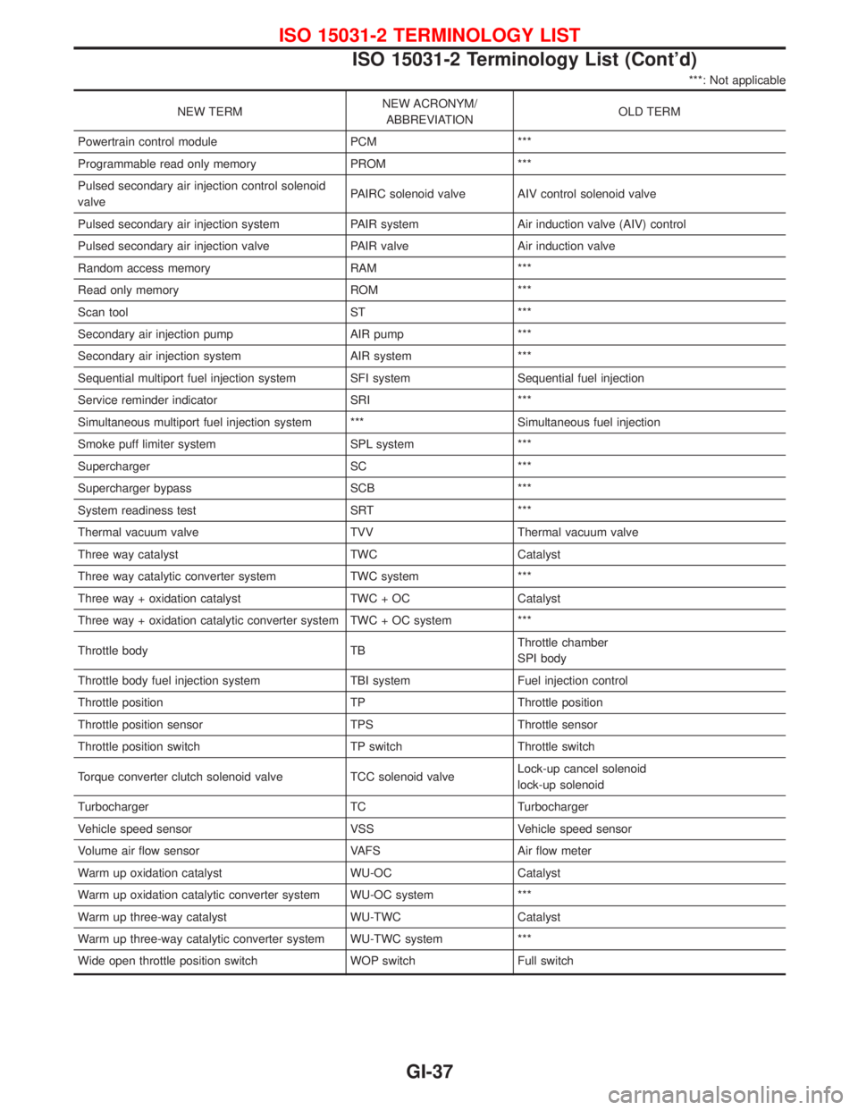
***: Not applicable
NEW TERMNEW ACRONYM/
ABBREVIATIONOLD TERM
Powertrain control module PCM ***
Programmable read only memory PROM ***
Pulsed secondary air injection control solenoid
valvePAIRC solenoid valve AIV control solenoid valve
Pulsed secondary air injection system PAIR system Air induction valve (AIV) control
Pulsed secondary air injection valve PAIR valve Air induction valve
Random access memory RAM ***
Read only memory ROM ***
Scan tool ST ***
Secondary air injection pump AIR pump ***
Secondary air injection system AIR system ***
Sequential multiport fuel injection system SFI system Sequential fuel injection
Service reminder indicator SRI ***
Simultaneous multiport fuel injection system *** Simultaneous fuel injection
Smoke puff limiter system SPL system ***
Supercharger SC ***
Supercharger bypass SCB ***
System readiness test SRT ***
Thermal vacuum valve TVV Thermal vacuum valve
Three way catalyst TWC Catalyst
Three way catalytic converter system TWC system ***
Three way + oxidation catalyst TWC + OC Catalyst
Three way + oxidation catalytic converter system TWC + OC system ***
Throttle body TBThrottle chamber
SPI body
Throttle body fuel injection system TBI system Fuel injection control
Throttle position TP Throttle position
Throttle position sensor TPS Throttle sensor
Throttle position switch TP switch Throttle switch
Torque converter clutch solenoid valve TCC solenoid valveLock-up cancel solenoid
lock-up solenoid
Turbocharger TC Turbocharger
Vehicle speed sensor VSS Vehicle speed sensor
Volume air flow sensor VAFS Air flow meter
Warm up oxidation catalyst WU-OC Catalyst
Warm up oxidation catalytic converter system WU-OC system ***
Warm up three-way catalyst WU-TWC Catalyst
Warm up three-way catalytic converter system WU-TWC system ***
Wide open throttle position switch WOP switch Full switch
ISO 15031-2 TERMINOLOGY LIST
ISO 15031-2 Terminology List (Cont'd)
GI-37