2002 NISSAN TERRANO oil filter
[x] Cancel search: oil filterPage 143 of 1767
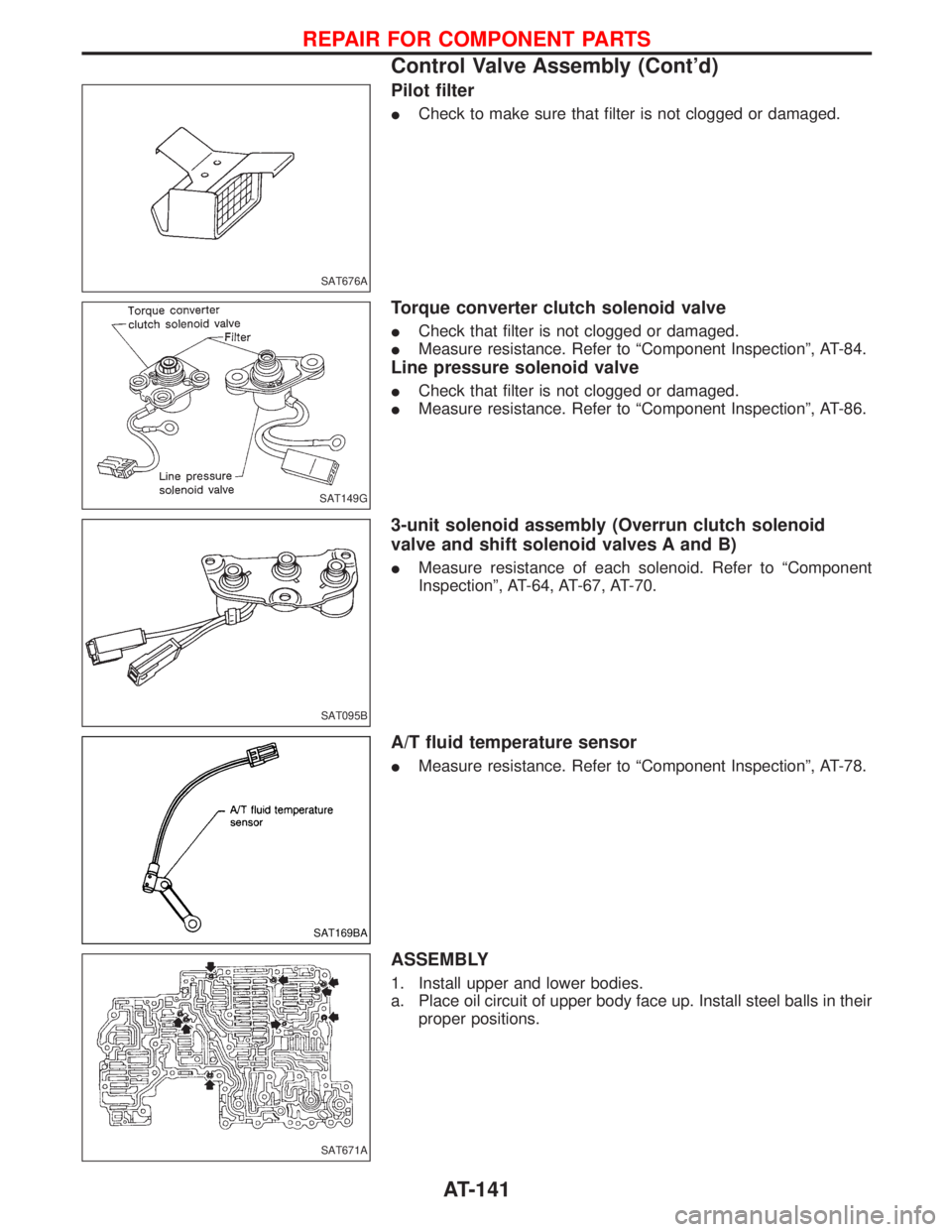
Pilot filter
ICheck to make sure that filter is not clogged or damaged.
Torque converter clutch solenoid valve
ICheck that filter is not clogged or damaged.
IMeasure resistance. Refer to ªComponent Inspectionº, AT-84.
Line pressure solenoid valve
ICheck that filter is not clogged or damaged.
IMeasure resistance. Refer to ªComponent Inspectionº, AT-86.
3-unit solenoid assembly (Overrun clutch solenoid
valve and shift solenoid valves A and B)
IMeasure resistance of each solenoid. Refer to ªComponent
Inspectionº, AT-64, AT-67, AT-70.
A/T fluid temperature sensor
IMeasure resistance. Refer to ªComponent Inspectionº, AT-78.
ASSEMBLY
1. Install upper and lower bodies.
a. Place oil circuit of upper body face up. Install steel balls in their
proper positions.
SAT676A
SAT149G
SAT095B
SAT169BA
SAT671A
REPAIR FOR COMPONENT PARTS
Control Valve Assembly (Cont'd)
AT-141
Page 144 of 1767
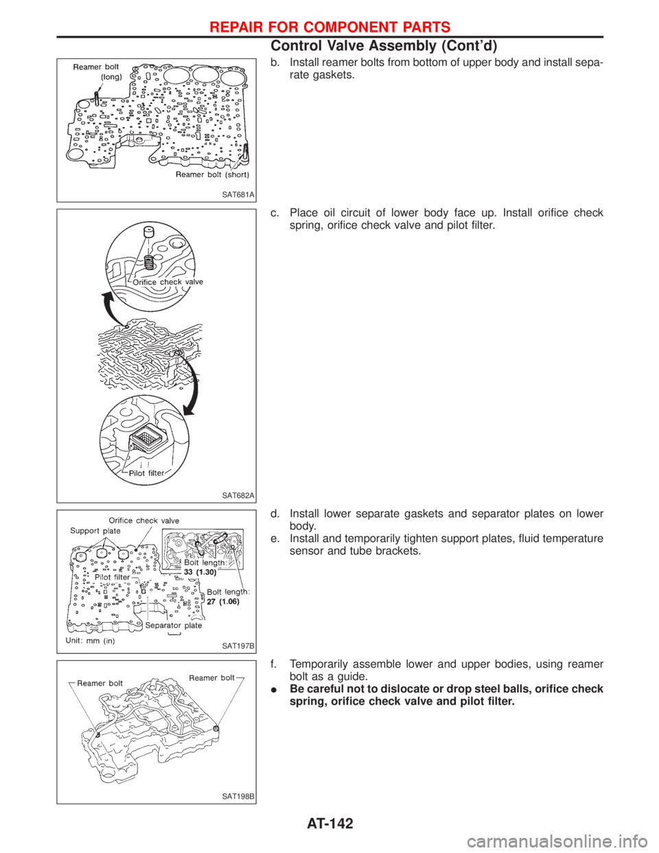
b. Install reamer bolts from bottom of upper body and install sepa-
rate gaskets.
c. Place oil circuit of lower body face up. Install orifice check
spring, orifice check valve and pilot filter.
d. Install lower separate gaskets and separator plates on lower
body.
e. Install and temporarily tighten support plates, fluid temperature
sensor and tube brackets.
f. Temporarily assemble lower and upper bodies, using reamer
bolt as a guide.
IBe careful not to dislocate or drop steel balls, orifice check
spring, orifice check valve and pilot filter.
SAT681A
SAT682A
SAT197B
SAT198B
REPAIR FOR COMPONENT PARTS
Control Valve Assembly (Cont'd)
AT-142
Page 1209 of 1767
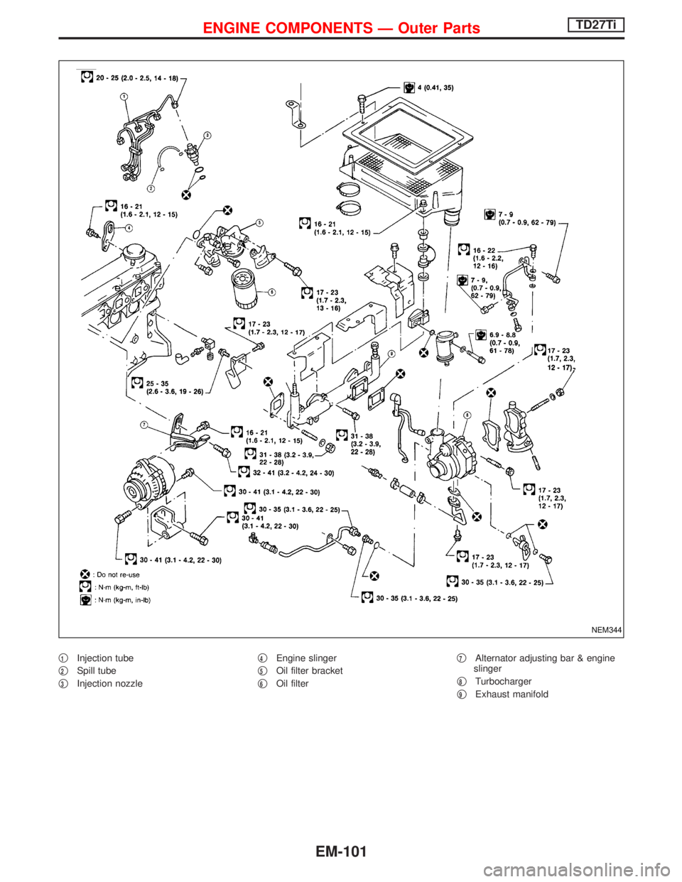
q1Injection tube
q
2Spill tube
q
3Injection nozzleq
4Engine slinger
q
5Oil filter bracket
q
6Oil filterq
7Alternator adjusting bar & engine
slinger
q
8Turbocharger
q
9Exhaust manifold
NEM344
ENGINE COMPONENTS Ð Outer PartsTD27Ti
EM-101
Page 1233 of 1767
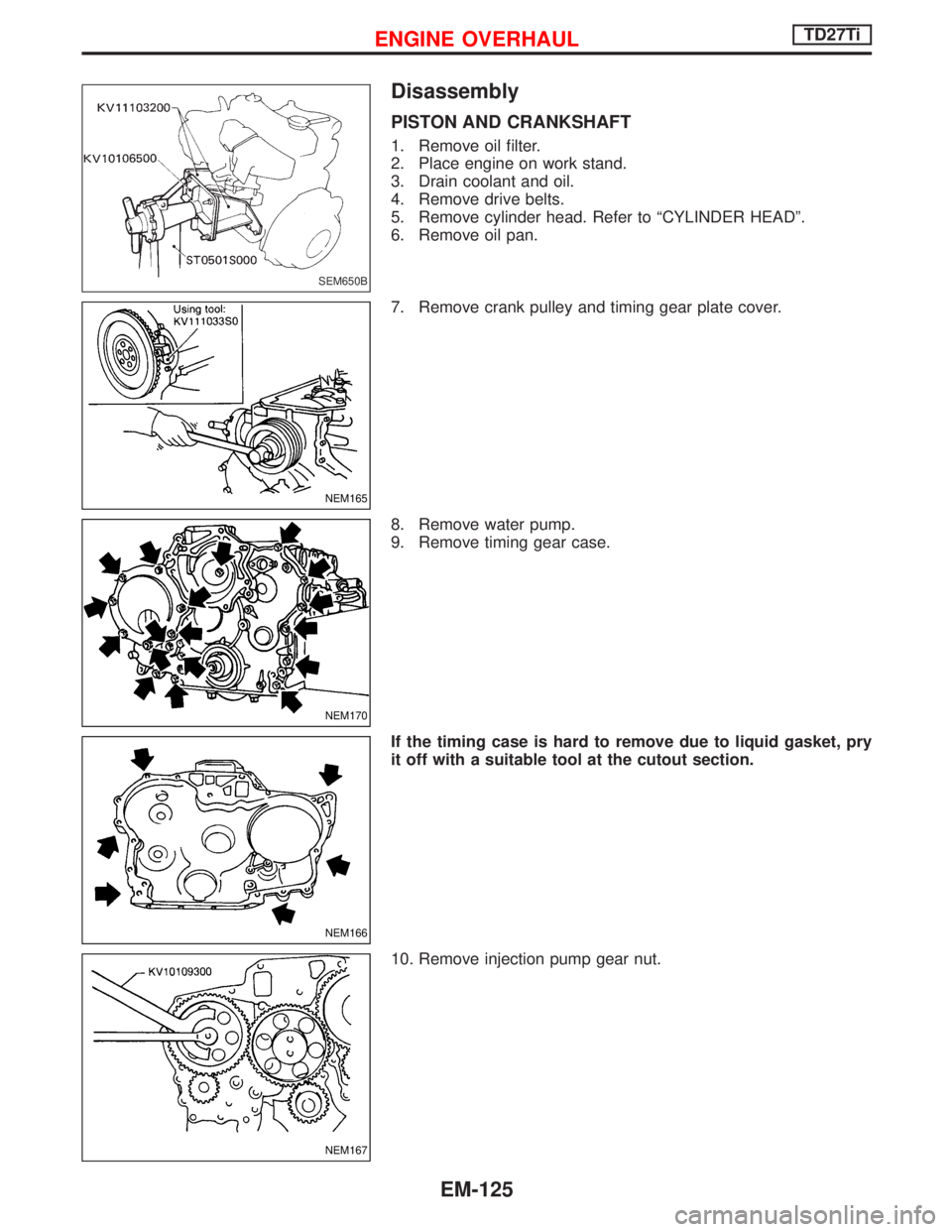
Disassembly
PISTON AND CRANKSHAFT
1. Remove oil filter.
2. Place engine on work stand.
3. Drain coolant and oil.
4. Remove drive belts.
5. Remove cylinder head. Refer to ªCYLINDER HEADº.
6. Remove oil pan.
7. Remove crank pulley and timing gear plate cover.
8. Remove water pump.
9. Remove timing gear case.
If the timing case is hard to remove due to liquid gasket, pry
it off with a suitable tool at the cutout section.
10. Remove injection pump gear nut.
SEM650B
NEM165
NEM170
NEM166
NEM167
ENGINE OVERHAULTD27Ti
EM-125
Page 1322 of 1767
Dispose of used oil and used oil filters through authorized waste
disposal contractors to licensed waste disposal sites, or to the
waste oil reclamation trade. If in doubt, contact the local authority
for advice on disposal facilities.
It is illegal to pour used oil on to the ground, down sewers or drains,
or into water courses.
The regulations concerning the pollution of the environment
will vary from country to country.
PRECAUTIONS
Precautions for Engine Oils (Cont'd)
GI-7
Page 1420 of 1767
Clutch pedal .............................................CL-3, 4, 5
Clutch release mechanism ...............................CL-9
Coil spring (rear) ......................................RA-14, 16
Collision diagnosis..........................................RS-57
Combination lamp, front, removal and
installation .....................................................BT-6
Combination lamp, rear, removal and
installation .....................................................BT-8
Combination meter (needle type) ...................EL-70
Combination meter removal and instal-
lation - See Instrument panel......................BT-16
Combination switch...................................EL-23, 24
Component Location (manual A/C) ..................HA-7
Compression pressure ...................................EM-10
Compressor clutch removal and
installation ...................................................HA-24
Compressor mounting ....................................HA-21
Connecting rod...............................................EM-73
Connecting rod bearing clearance.................EM-77
Connecting rod bushing clearance ................EM-73
Console box - See Instrument panel ..............BT-16
CONSULT for ABS .........................................BR-58
CONSULT for engine .............................EC-39, 327
CONSULT-II general information.....................GI-26
Control lever (M/T) .........................................MT-13
Control lever (Transfer) .....................................TF-8
Control sleeve position sensor .....................EC-414
Control valve (A/T) ........................................AT-113
COOL/F - Wiring diagram ............................EC-112
Coolant mixture ratio ...................MA-17, 20, 22, 31
Coolant replacement ...............MA-5, 17, 20, 22, 31
Cooling circuit (engine)...............................LC-9, 27
Cooling fan ...............................................LC-15, 33
Cooling fan control .......................................EC-109
Cooling fan relay ..........................................EC-426
Corrosion protection..........................................BT-5
Counter gear (M/T) .........................................MT-11
Counter gear (Transfer) ............................TF-10, 20
Cowl top ..........................................................BT-21
Cowl top cover ................................................BT-21
Crankcase emission control system -
See positive crankcase ventilation .....EC-23, 312
Crankcase ventilation system - See
Positive crankcase ventilation ............EC-23, 312
Crankshaft ......................................................EM-76
Crankshaft position sensor (TDC) .......EC-145, 385
Cylinder block ................................................EM-66
Cylinder head .................................................EM-52
D
Data link connector ................................EC-39, 327
Daytime light system ..........................EL-29, 30, 31
DEF - Wiring diagram ...................................EL-107
Defroster door control rod adjustment ...........HA-62
Diagnosis sensor unit .....................................RS-11
Diagnostic trouble code (DTC) for OBD
system ................................................EC-33, 321
Differential carrier assembly ....................PD-29, 53Differential carrier disassembly..........PD-18, 38, 40
Differential gear oil replacement .......MA-36, 38, 39
Dimensions ......................................................GI-31
D/LOCK - Wiring diagram .............................EL-140
Door glass .......................................................BT-10
Door lock .........................................................BT-10
Door mirror ......................................................BT-48
Door trim .........................................................BT-19
Door, front .......................................................BT-10
Door, rear ........................................................BT-12
Drive belt inspection ................................MA-20, 28
Drive chain (Transfer) .....................................TF-10
Drive pinion diff. inspection ......................PD-20, 42
Drive pinion height ...................................PD-21, 49
Drive plate runout ..........................................EM-94
Drive shaft ........................................................MA-5
Drive shaft (front)..................................FA-4, 12, 22
Driver air bag..................................................RS-14
Dropping resistor (A/T)....................................AT-86
Dual pressure switch..................................HA-9, 61
E
ECM input/output signal .........................EC-69, 346
ECM relay ......................................EC-80, 209, 353
ECMRLY - Wiring diagram ...........................EC-210
ECTS - Wiring diagram ..................................EC-96
EGR control (EGRC) - solenoid valve .........EC-431
EGR control valve ........................................EC-439
EGR volume control valve ...........................EC-222
EGVC/V - Wiring diagram ............................EC-225
Electrical unit ................................................Foldout
Electronic fuel injection pump ......................EC-318
Engine compartment .......................................BT-50
Engine control circuit diagram ...............EC-16, 302
Engine control component parts
location ...............................................EC-12, 300
Engine control module (ECM) ......EC-69, 121, 200,
202, 213, 346,
407, 444
Engine control system diagram and
chart....................................................EC-17, 303
Engine coolant temperature sensor
(ECTS)................................................EC-95, 361
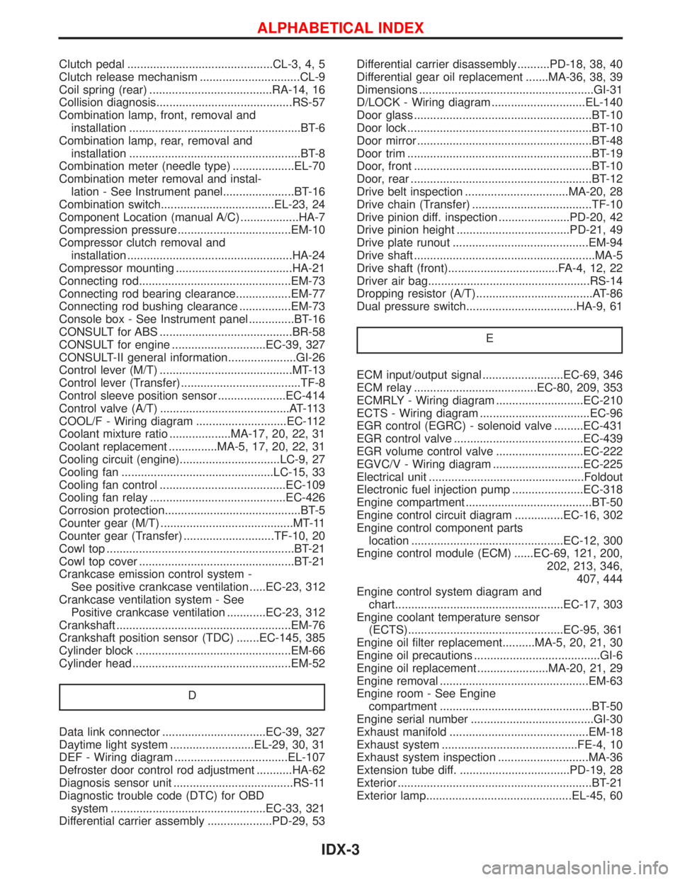
Engine oil filter replacement..........MA-5, 20, 21, 30
Engine oil precautions .......................................GI-6
Engine oil replacement ......................MA-20, 21, 29
Engine removal ..............................................EM-63
Engine room - See Engine
compartment ...............................................BT-50
Engine serial number ......................................GI-30
Exhaust manifold ...........................................EM-18
Exhaust system ..........................................FE-4, 10
Exhaust system inspection ............................MA-36
Extension tube diff. ..................................PD-19, 28
Exterior ............................................................BT-21
Exterior lamp.............................................EL-45, 60
ALPHABETICAL INDEX
IDX-3
Page 1426 of 1767
ENGINE LUBRICATION &
COOLING SYSTEMS
SECTION
LC
CONTENTS
ZD
PRECAUTIONS AND PREPARATION............................2
Liquid Gasket Application Procedure ..........................2
Special Service Tools ..................................................2
ENGINE LUBRICATION SYSTEM..................................3
Lubricating Circuit ........................................................3
Oil Pressure Check......................................................4
Oil Pump ......................................................................5
Oil Jet...........................................................................7
Oil Cooler .....................................................................8
ENGINE COOLING SYSTEM..........................................9
Cooling Circuit .............................................................9
System Check............................................................10
Water Pump ............................................................... 11
Thermostat .................................................................12
Water Outlet ...............................................................13
Radiator .....................................................................14
Cooling Fan (Crankshaft driven) ...............................15
EGR Cooler ...............................................................16
SERVICE DATA AND SPECIFICATIONS (SDS)..........17
Engine Lubrication System ........................................17
Engine Cooling System .............................................17TD27TiPREPARATION..............................................................18
PRECAUTION................................................................19
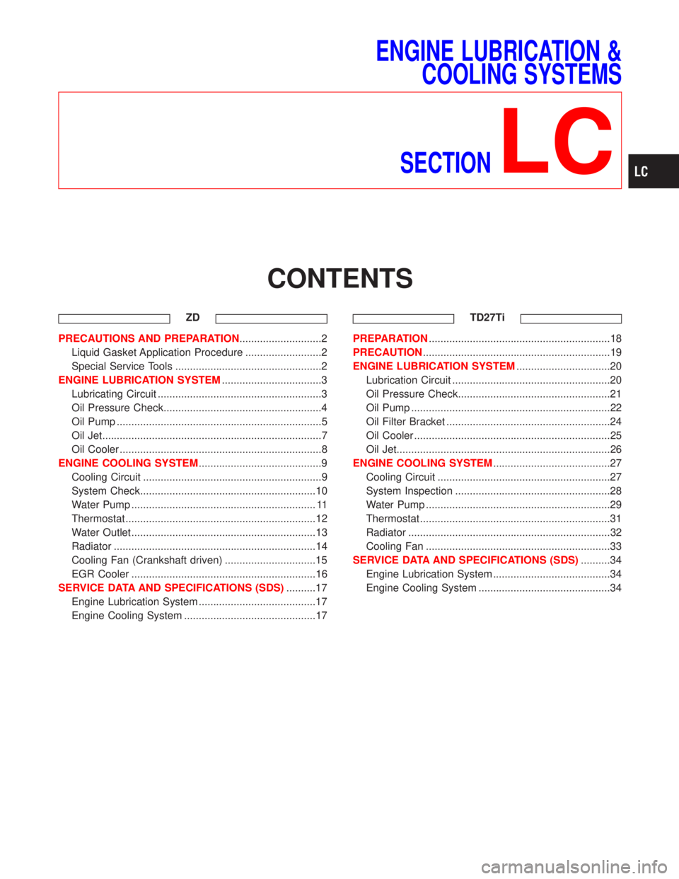
ENGINE LUBRICATION SYSTEM................................20
Lubrication Circuit ......................................................20
Oil Pressure Check....................................................21
Oil Pump ....................................................................22
Oil Filter Bracket ........................................................24
Oil Cooler ...................................................................25
Oil Jet.........................................................................26
ENGINE COOLING SYSTEM........................................27
Cooling Circuit ...........................................................27
System Inspection .....................................................28
Water Pump ...............................................................29
Thermostat .................................................................31
Radiator .....................................................................32
Cooling Fan ...............................................................33
SERVICE DATA AND SPECIFICATIONS (SDS)..........34
Engine Lubrication System ........................................34
Engine Cooling System .............................................34
Page 1433 of 1767
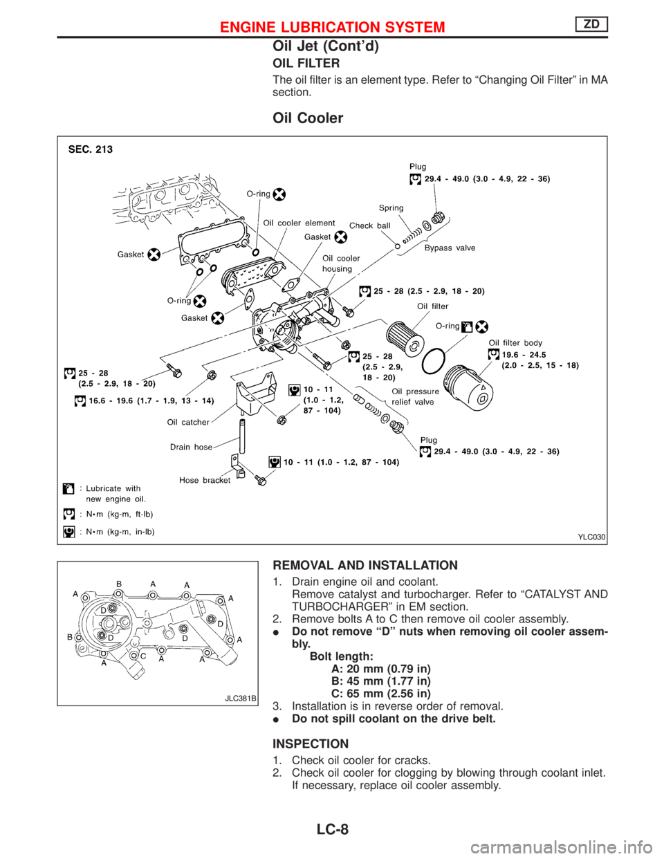
OIL FILTER
The oil filter is an element type. Refer to ªChanging Oil Filterº in MA
section.
Oil Cooler
REMOVAL AND INSTALLATION
1. Drain engine oil and coolant.
Remove catalyst and turbocharger. Refer to ªCATALYST AND
TURBOCHARGERº in EM section.
2. Remove bolts A to C then remove oil cooler assembly.
IDo not remove ªDº nuts when removing oil cooler assem-
bly.
Bolt length:
A: 20 mm (0.79 in)
B: 45 mm (1.77 in)
C: 65 mm (2.56 in)
3. Installation is in reverse order of removal.
IDo not spill coolant on the drive belt.
INSPECTION
1. Check oil cooler for cracks.
2. Check oil cooler for clogging by blowing through coolant inlet.
If necessary, replace oil cooler assembly.
YLC030
JLC381B
ENGINE LUBRICATION SYSTEMZD
Oil Jet (Cont'd)
LC-8