2002 NISSAN TERRANO compression ratio
[x] Cancel search: compression ratioPage 1206 of 1767
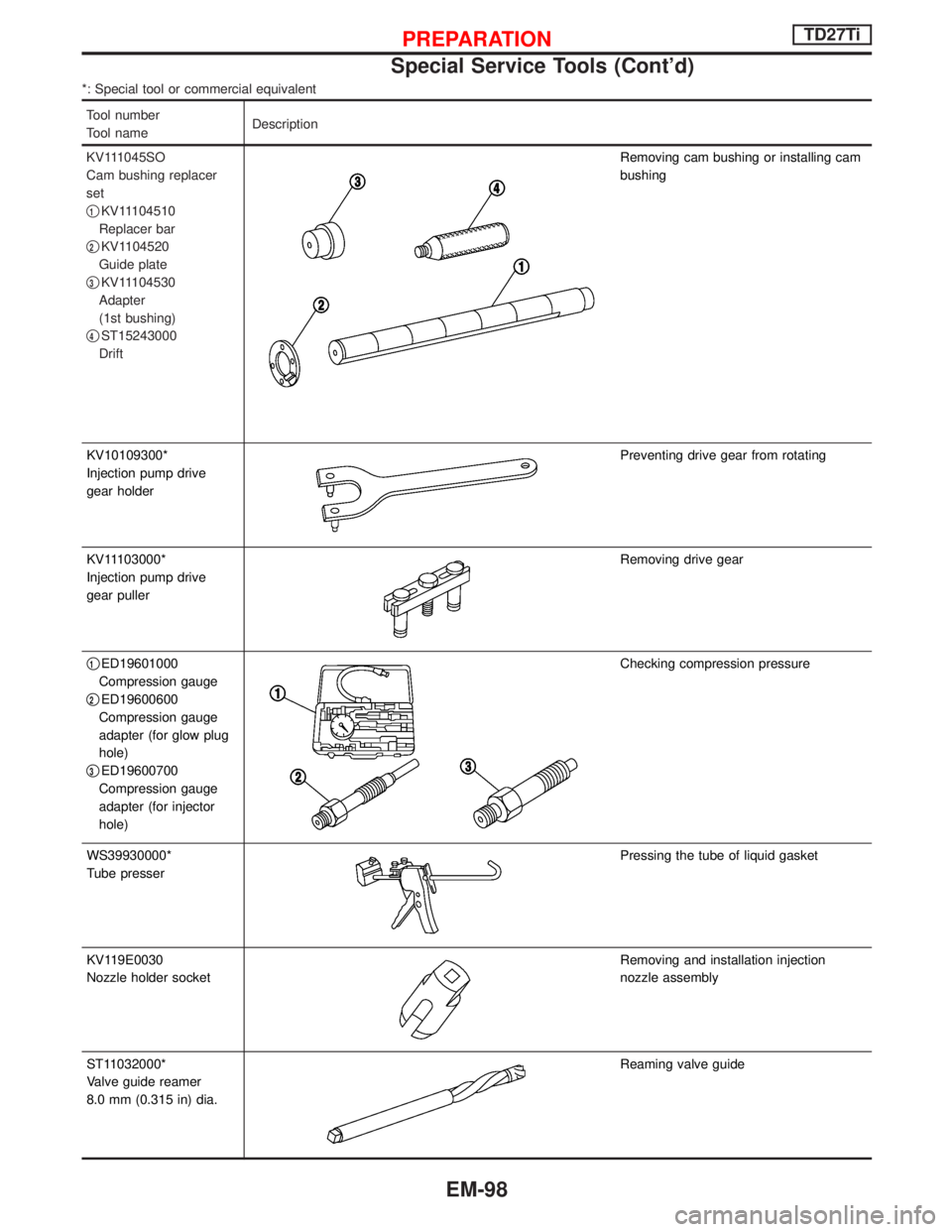
*: Special tool or commercial equivalent
Tool number
Tool nameDescription
KV111045SO
Cam bushing replacer
set
q
1KV11104510
Replacer bar
q
2KV1104520
Guide plate
q
3KV11104530
Adapter
(1st bushing)
q
4ST15243000
Drift
Removing cam bushing or installing cam
bushing
KV10109300*
Injection pump drive
gear holder
Preventing drive gear from rotating
KV11103000*
Injection pump drive
gear puller
Removing drive gear
q
1ED19601000
Compression gauge
q
2ED19600600
Compression gauge
adapter (for glow plug
hole)
q
3ED19600700
Compression gauge
adapter (for injector
hole)
Checking compression pressure
WS39930000*
Tube presser
Pressing the tube of liquid gasket
KV119E0030
Nozzle holder socket
Removing and installation injection
nozzle assembly
ST11032000*
Valve guide reamer
8.0 mm (0.315 in) dia.
Reaming valve guide
PREPARATIONTD27Ti
Special Service Tools (Cont'd)
EM-98
Page 1251 of 1767
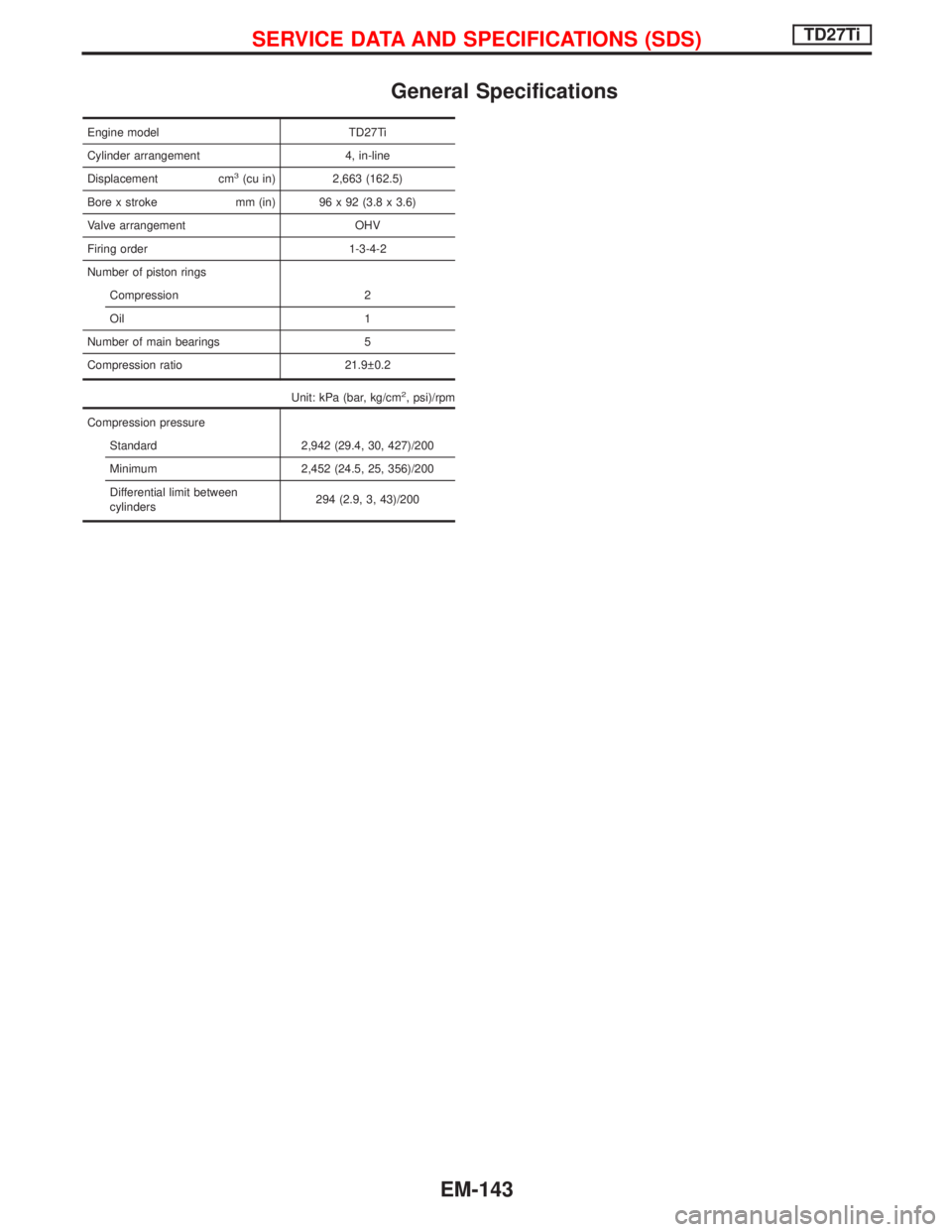
General Specifications
Engine model TD27Ti
Cylinder arrangement 4, in-line
Displacement cm
3(cu in) 2,663 (162.5)
Bore x stroke mm (in) 96 x 92 (3.8 x 3.6)
Valve arrangement OHV
Firing order 1-3-4-2
Number of piston rings
Compression 2
Oil 1
Number of main bearings 5
Compression ratio 21.9 0.2
Unit: kPa (bar, kg/cm
2, psi)/rpm
Compression pressure
Standard 2,942 (29.4, 30, 427)/200
Minimum 2,452 (24.5, 25, 356)/200
Differential limit between
cylinders294 (2.9, 3, 43)/200
SERVICE DATA AND SPECIFICATIONS (SDS)TD27Ti
EM-143
Page 1259 of 1767
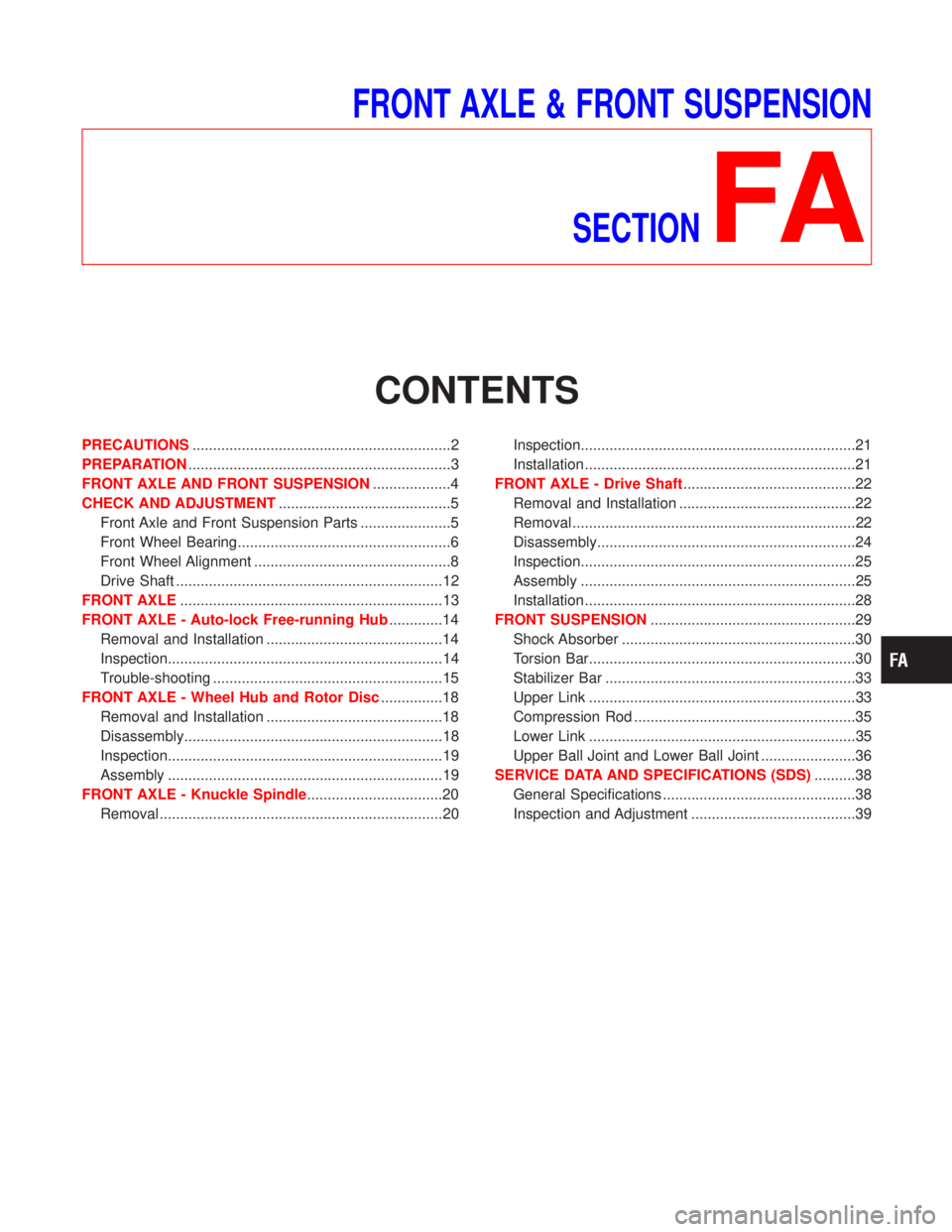
FRONT AXLE & FRONT SUSPENSION
SECTION
FA
CONTENTS
PRECAUTIONS...............................................................2
PREPARATION................................................................3
FRONT AXLE AND FRONT SUSPENSION...................4
CHECK AND ADJUSTMENT..........................................5
Front Axle and Front Suspension Parts ......................5
Front Wheel Bearing....................................................6
Front Wheel Alignment ................................................8
Drive Shaft .................................................................12
FRONT AXLE................................................................13
FRONT AXLE - Auto-lock Free-running Hub.............14
Removal and Installation ...........................................14
Inspection...................................................................14
Trouble-shooting ........................................................15
FRONT AXLE - Wheel Hub and Rotor Disc...............18
Removal and Installation ...........................................18
Disassembly...............................................................18
Inspection...................................................................19
Assembly ...................................................................19
FRONT AXLE - Knuckle Spindle.................................20
Removal .....................................................................20Inspection...................................................................21
Installation ..................................................................21
FRONT AXLE - Drive Shaft..........................................22
Removal and Installation ...........................................22
Removal .....................................................................22
Disassembly...............................................................24
Inspection...................................................................25
Assembly ...................................................................25
Installation ..................................................................28
FRONT SUSPENSION..................................................29
Shock Absorber .........................................................30
Torsion Bar.................................................................30
Stabilizer Bar .............................................................33
Upper Link .................................................................33
Compression Rod ......................................................35
Lower Link .................................................................35
Upper Ball Joint and Lower Ball Joint .......................36
SERVICE DATA AND SPECIFICATIONS (SDS)..........38
General Specifications ...............................................38
Inspection and Adjustment ........................................39
Page 1296 of 1767
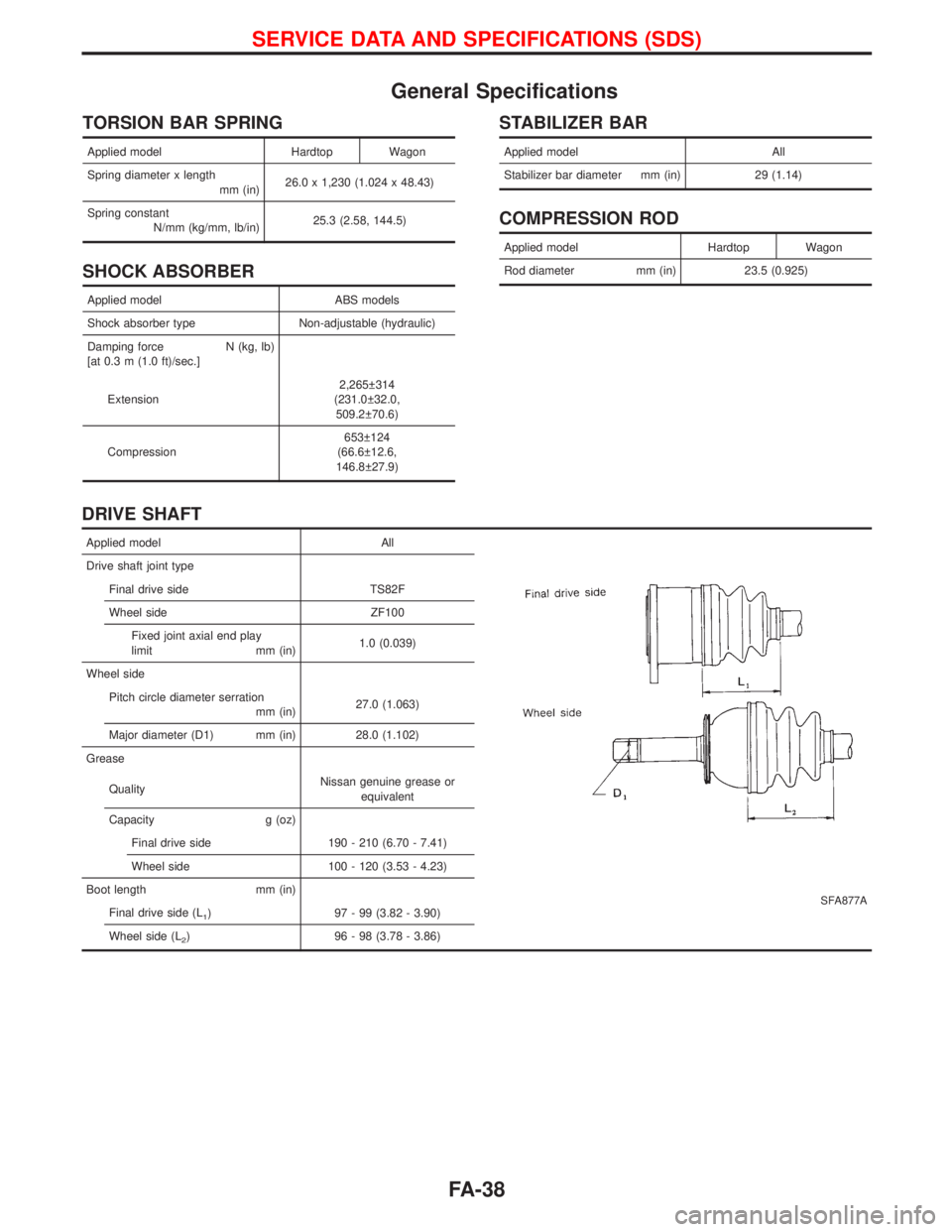
General Specifications
TORSION BAR SPRING
Applied model Hardtop Wagon
Spring diameter x length
mm (in)26.0 x 1,230 (1.024 x 48.43)
Spring constant
N/mm (kg/mm, lb/in)25.3 (2.58, 144.5)
SHOCK ABSORBER
Applied model ABS models
Shock absorber type Non-adjustable (hydraulic)
Damping force N (kg, lb)
[at 0.3 m (1.0 ft)/sec.]
Extension2,265 314
(231.0 32.0,
509.2 70.6)
Compression653 124
(66.6 12.6,
146.8 27.9)
STABILIZER BAR
Applied model All
Stabilizer bar diameter mm (in) 29 (1.14)
COMPRESSION ROD
Applied model Hardtop Wagon
Rod diameter mm (in) 23.5 (0.925)
DRIVE SHAFT
Applied model All
SFA877A
Drive shaft joint type
Final drive side TS82F
Wheel side ZF100
Fixed joint axial end play
limit mm (in)1.0 (0.039)
Wheel side
Pitch circle diameter serration
mm (in)27.0 (1.063)
Major diameter (D1) mm (in) 28.0 (1.102)
Grease
QualityNissan genuine grease or
equivalent
Capacity g (oz)
Final drive side 190 - 210 (6.70 - 7.41)
Wheel side 100 - 120 (3.53 - 4.23)
Boot length mm (in)
Final drive side (L
1) 97 - 99 (3.82 - 3.90)
Wheel side (L
2) 96 - 98 (3.78 - 3.86)
SERVICE DATA AND SPECIFICATIONS (SDS)
FA-38
Page 1320 of 1767
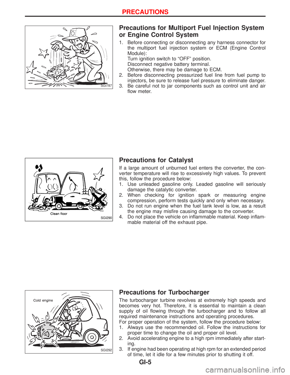
Precautions for Multiport Fuel Injection System
or Engine Control System
1. Before connecting or disconnecting any harness connector for
the multiport fuel injection system or ECM (Engine Control
Module):
Turn ignition switch to ªOFFº position.
Disconnect negative battery terminal.
Otherwise, there may be damage to ECM.
2. Before disconnecting pressurized fuel line from fuel pump to
injectors, be sure to release fuel pressure to eliminate danger.
3. Be careful not to jar components such as control unit and air
flow meter.
Precautions for Catalyst
If a large amount of unburned fuel enters the converter, the con-
verter temperature will rise to excessively high values. To prevent
this, follow the procedure below:
1. Use unleaded gasoline only. Leaded gasoline will seriously
damage the catalytic converter.
2. When checking for ignition spark or measuring engine
compression, perform tests quickly and only when necessary.
3. Do not run engine when the fuel tank level is low, as a result
the engine may misfire causing damage to the converter.
4. Do not place the vehicle on inflammable material. Keep inflam-
mable material off the exhaust pipe.
Precautions for Turbocharger
The turbocharger turbine revolves at extremely high speeds and
becomes very hot. Therefore, it is essential to maintain a clean
supply of oil flowing through the turbocharger and to follow all
required maintenance instructions and operating procedures.
For proper operation of the system, follow the procedure below:
1. Always use the recommended oil. Follow the instructions for
proper time to change the oil and proper oil level.
2. Avoid accelerating engine to a high rpm immediately after start-
ing.
3. If engine had been operating at high rpm for an extended period
of time, let it idle for a few minutes prior to shutting it off.
SGI787
SGI290
SGI292
PRECAUTIONS
GI-5
Page 1420 of 1767
Clutch pedal .............................................CL-3, 4, 5
Clutch release mechanism ...............................CL-9
Coil spring (rear) ......................................RA-14, 16
Collision diagnosis..........................................RS-57
Combination lamp, front, removal and
installation .....................................................BT-6
Combination lamp, rear, removal and
installation .....................................................BT-8
Combination meter (needle type) ...................EL-70
Combination meter removal and instal-
lation - See Instrument panel......................BT-16
Combination switch...................................EL-23, 24
Component Location (manual A/C) ..................HA-7
Compression pressure ...................................EM-10
Compressor clutch removal and
installation ...................................................HA-24
Compressor mounting ....................................HA-21
Connecting rod...............................................EM-73
Connecting rod bearing clearance.................EM-77
Connecting rod bushing clearance ................EM-73
Console box - See Instrument panel ..............BT-16
CONSULT for ABS .........................................BR-58
CONSULT for engine .............................EC-39, 327
CONSULT-II general information.....................GI-26
Control lever (M/T) .........................................MT-13
Control lever (Transfer) .....................................TF-8
Control sleeve position sensor .....................EC-414
Control valve (A/T) ........................................AT-113
COOL/F - Wiring diagram ............................EC-112
Coolant mixture ratio ...................MA-17, 20, 22, 31
Coolant replacement ...............MA-5, 17, 20, 22, 31
Cooling circuit (engine)...............................LC-9, 27
Cooling fan ...............................................LC-15, 33
Cooling fan control .......................................EC-109
Cooling fan relay ..........................................EC-426
Corrosion protection..........................................BT-5
Counter gear (M/T) .........................................MT-11
Counter gear (Transfer) ............................TF-10, 20
Cowl top ..........................................................BT-21
Cowl top cover ................................................BT-21
Crankcase emission control system -
See positive crankcase ventilation .....EC-23, 312
Crankcase ventilation system - See
Positive crankcase ventilation ............EC-23, 312
Crankshaft ......................................................EM-76
Crankshaft position sensor (TDC) .......EC-145, 385
Cylinder block ................................................EM-66
Cylinder head .................................................EM-52
D
Data link connector ................................EC-39, 327
Daytime light system ..........................EL-29, 30, 31
DEF - Wiring diagram ...................................EL-107
Defroster door control rod adjustment ...........HA-62
Diagnosis sensor unit .....................................RS-11
Diagnostic trouble code (DTC) for OBD
system ................................................EC-33, 321
Differential carrier assembly ....................PD-29, 53Differential carrier disassembly..........PD-18, 38, 40
Differential gear oil replacement .......MA-36, 38, 39
Dimensions ......................................................GI-31
D/LOCK - Wiring diagram .............................EL-140
Door glass .......................................................BT-10
Door lock .........................................................BT-10
Door mirror ......................................................BT-48
Door trim .........................................................BT-19
Door, front .......................................................BT-10
Door, rear ........................................................BT-12
Drive belt inspection ................................MA-20, 28
Drive chain (Transfer) .....................................TF-10
Drive pinion diff. inspection ......................PD-20, 42
Drive pinion height ...................................PD-21, 49
Drive plate runout ..........................................EM-94
Drive shaft ........................................................MA-5
Drive shaft (front)..................................FA-4, 12, 22
Driver air bag..................................................RS-14
Dropping resistor (A/T)....................................AT-86
Dual pressure switch..................................HA-9, 61
E
ECM input/output signal .........................EC-69, 346
ECM relay ......................................EC-80, 209, 353
ECMRLY - Wiring diagram ...........................EC-210
ECTS - Wiring diagram ..................................EC-96
EGR control (EGRC) - solenoid valve .........EC-431
EGR control valve ........................................EC-439
EGR volume control valve ...........................EC-222
EGVC/V - Wiring diagram ............................EC-225
Electrical unit ................................................Foldout
Electronic fuel injection pump ......................EC-318
Engine compartment .......................................BT-50
Engine control circuit diagram ...............EC-16, 302
Engine control component parts
location ...............................................EC-12, 300
Engine control module (ECM) ......EC-69, 121, 200,
202, 213, 346,
407, 444
Engine control system diagram and
chart....................................................EC-17, 303
Engine coolant temperature sensor
(ECTS)................................................EC-95, 361
Engine oil filter replacement..........MA-5, 20, 21, 30
Engine oil precautions .......................................GI-6
Engine oil replacement ......................MA-20, 21, 29
Engine removal ..............................................EM-63
Engine room - See Engine
compartment ...............................................BT-50
Engine serial number ......................................GI-30
Exhaust manifold ...........................................EM-18
Exhaust system ..........................................FE-4, 10
Exhaust system inspection ............................MA-36
Extension tube diff. ..................................PD-19, 28
Exterior ............................................................BT-21
Exterior lamp.............................................EL-45, 60
ALPHABETICAL INDEX
IDX-3