Page 236 of 1767
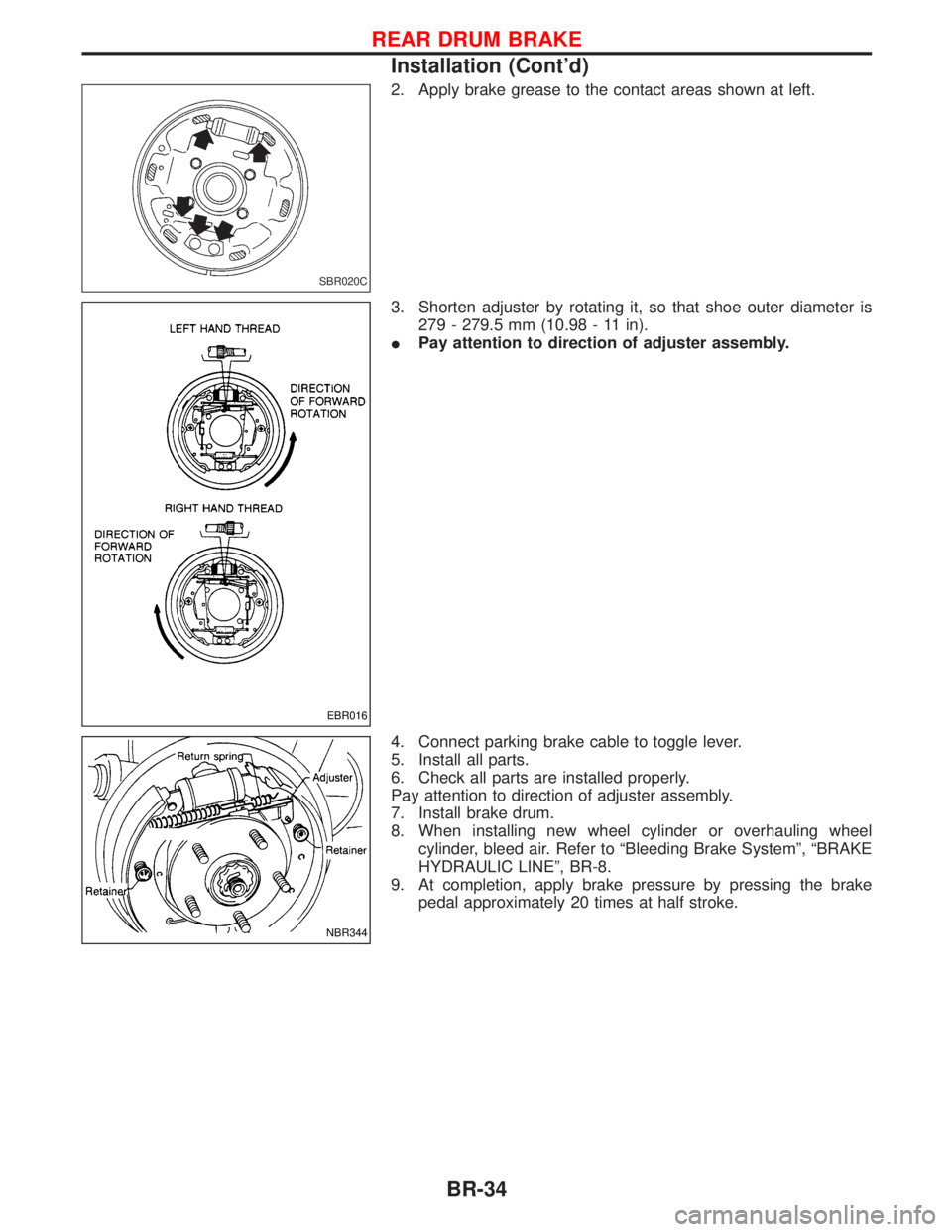
2. Apply brake grease to the contact areas shown at left.
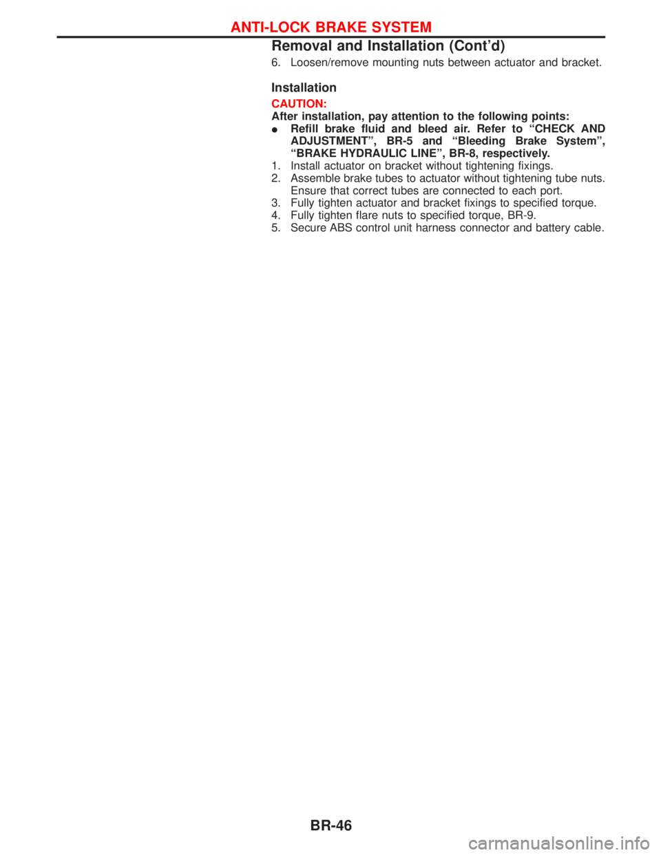
3. Shorten adjuster by rotating it, so that shoe outer diameter is
279 - 279.5 mm (10.98 - 11 in).
IPay attention to direction of adjuster assembly.
4. Connect parking brake cable to toggle lever.
5. Install all parts.
6. Check all parts are installed properly.
Pay attention to direction of adjuster assembly.
7. Install brake drum.
8. When installing new wheel cylinder or overhauling wheel
cylinder, bleed air. Refer to ªBleeding Brake Systemº, ªBRAKE
HYDRAULIC LINEº, BR-8.
9. At completion, apply brake pressure by pressing the brake
pedal approximately 20 times at half stroke.
SBR020C
EBR016
NBR344
REAR DRUM BRAKE
Installation (Cont'd)
BR-34
Page 248 of 1767
6. Loosen/remove mounting nuts between actuator and bracket.
Installation
CAUTION:
After installation, pay attention to the following points:
IRefill brake fluid and bleed air. Refer to ªCHECK AND
ADJUSTMENTº, BR-5 and ªBleeding Brake Systemº,
ªBRAKE HYDRAULIC LINEº, BR-8, respectively.
1. Install actuator on bracket without tightening fixings.
2. Assemble brake tubes to actuator without tightening tube nuts.
Ensure that correct tubes are connected to each port.
3. Fully tighten actuator and bracket fixings to specified torque.
4. Fully tighten flare nuts to specified torque, BR-9.
5. Secure ABS control unit harness connector and battery cable.
ANTI-LOCK BRAKE SYSTEM
Removal and Installation (Cont'd)
BR-46
Page 354 of 1767
Bleeding Procedure
1. Bleed air from clutch operating cylinder according to the follow-
ing procedure.
Carefully monitor fluid level at master cylinder during bleeding
operation.
a. Top up reservoir with recommended brake fluid.
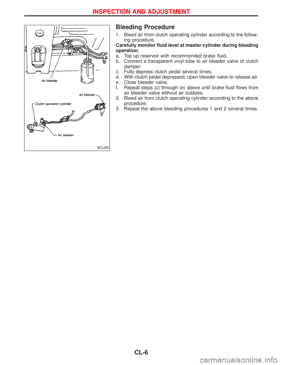
b. Connect a transparent vinyl tube to air bleeder valve of clutch
damper.
c. Fully depress clutch pedal several times.
d. With clutch pedal depressed, open bleeder valve to release air.
e. Close bleeder valve.
f. Repeat steps (c) through (e) above until brake fluid flows from
air bleeder valve without air bubbles.
2. Bleed air from clutch operating cylinder according to the above
procedure.
3. Repeat the above bleeding procedures 1 and 2 several times.
NCL025
INSPECTION AND ADJUSTMENT
CL-6
Page 363 of 1767
ENGINE CONTROL SYSTEM
SECTION
EC
CONTENTS
ZD30DDTi
TROUBLE DIAGNOSIS - INDEX....................................7
Alphabetical & Numerical Index for DTC ....................7
PRECAUTIONS...............................................................9
Precautions ..................................................................9
ENGINE AND EMISSION CONTROL OVERALL
SYSTEM.........................................................................12
Engine Control Component Parts Location ...............12
Circuit Diagram ..........................................................16
System Diagram ........................................................17
Vacuum Hose Drawing ..............................................18
System Chart .............................................................19
ENGINE AND EMISSION BASIC CONTROL
SYSTEM DESCRIPTION...............................................20
Fuel Injection Control System ...................................20
Fuel Injection Timing Control System........................22
Air Conditioning Cut Control ......................................22
Fuel Cut Control (at no load & high engine
speed) ........................................................................22
Crankcase Ventilation System ...................................23
BASIC SERVICE PROCEDURE...................................24
Injection Tube and Injection Nozzle ..........................24
Electronic Control Fuel Injection Pump .....................27
Air Bleeding ...............................................................32
ON BOARD DIAGNOSTIC SYSTEM
DESCRIPTION...............................................................33
DTC and MI Detection Logic .....................................33
Diagnostic Trouble Code (DTC) ................................33
Malfunction Indicator (MI) ..........................................34
CONSULT-II ...............................................................39
TROUBLE DIAGNOSIS - INTRODUCTION..................46
Introduction ................................................................46
Work Flow ..................................................................48
TROUBLE DIAGNOSIS - BASIC INSPECTION...........50
Basic Inspection.........................................................50
TROUBLE DIAGNOSIS - GENERAL
DESCRIPTION...............................................................56
Symptom Matrix Chart ...............................................56CONSULT-II Reference Value in Data Monitor
Mode ..........................................................................66
Major Sensor Reference Graph in Data Monitor
Mode ..........................................................................68
ECM Terminals and Reference Value .......................69
TROUBLE DIAGNOSIS FOR INTERMITTENT
INCIDENT.......................................................................78
Description .................................................................78
Diagnostic Procedure ................................................78
TROUBLE DIAGNOSIS FOR POWER SUPPLY..........79
Main Power Supply and Ground Circuit ....................79
DTC 0102 MASS AIR FLOW SEN................................88
Component Description .............................................88
CONSULT-II Reference Value in Data Monitor
Mode ..........................................................................88
ECM Terminals and Reference Value .......................88
On Board Diagnosis Logic.........................................88
DTC Confirmation Procedure ....................................89
Wiring Diagram ..........................................................90
Diagnostic Procedure ................................................92
DTC 0103 COOLANT TEMP SEN................................95
Description .................................................................95
On Board Diagnosis Logic.........................................95
DTC Confirmation Procedure ....................................95
Wiring Diagram ..........................................................96
Diagnostic Procedure ................................................97
DTC 0104 VEHICLE SPEED SEN................................99
Description .................................................................99
ECM Terminals and Reference Value .......................99
On Board Diagnosis Logic.........................................99
Overall Function Check ...........................................100
Wiring Diagram ........................................................101
Diagnostic Procedure ..............................................103
DTC 0203 ACCEL POS SW (F/C)..............................104
Description ...............................................................104
CONSULT-II Reference Value in Data Monitor
Mode ........................................................................104
ECM Terminals and Reference Value .....................104
On Board Diagnosis Logic.......................................104
Page 388 of 1767
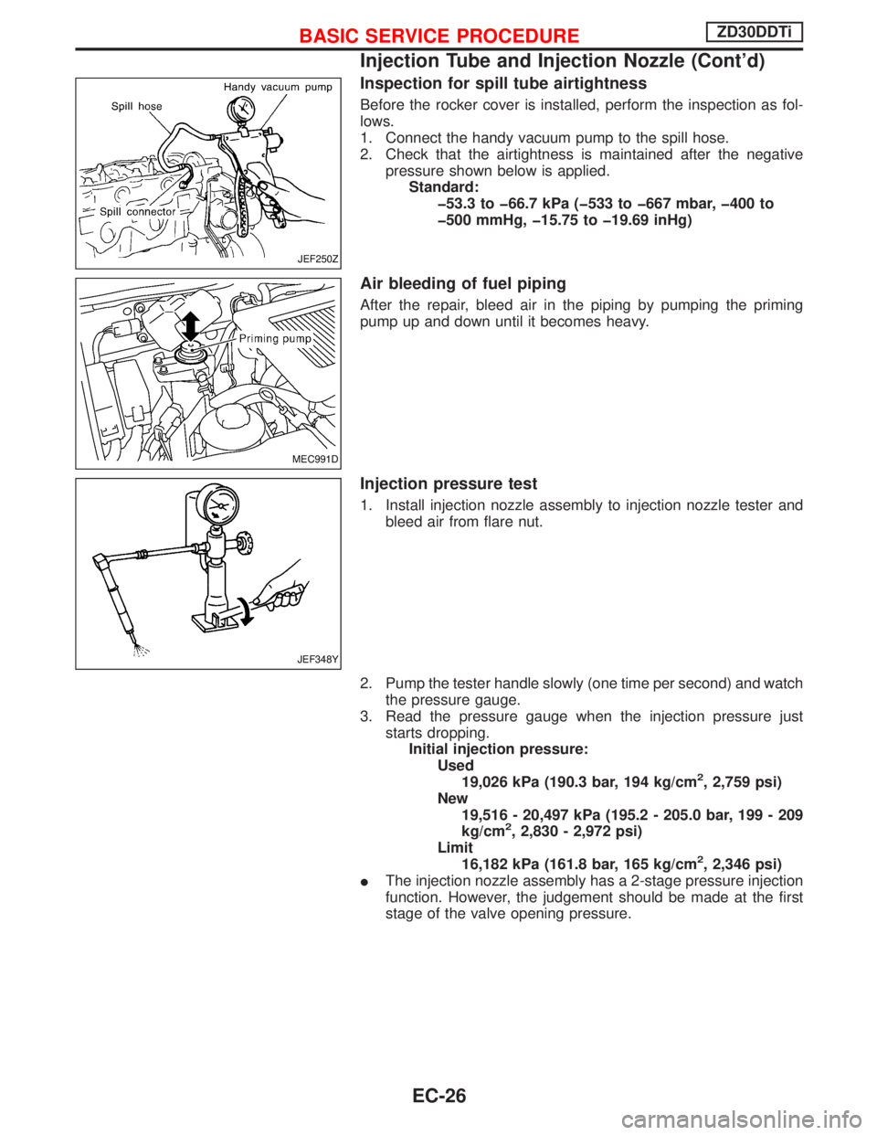
Inspection for spill tube airtightness
Before the rocker cover is installed, perform the inspection as fol-
lows.
1. Connect the handy vacuum pump to the spill hose.
2. Check that the airtightness is maintained after the negative
pressure shown below is applied.
Standard:
þ53.3 to þ66.7 kPa (þ533 to þ667 mbar, þ400 to
þ500 mmHg, þ15.75 to þ19.69 inHg)
Air bleeding of fuel piping
After the repair, bleed air in the piping by pumping the priming
pump up and down until it becomes heavy.
Injection pressure test
1. Install injection nozzle assembly to injection nozzle tester and
bleed air from flare nut.
2. Pump the tester handle slowly (one time per second) and watch
the pressure gauge.
3. Read the pressure gauge when the injection pressure just
starts dropping.
Initial injection pressure:
Used
19,026 kPa (190.3 bar, 194 kg/cm
2, 2,759 psi)
New
19,516 - 20,497 kPa (195.2 - 205.0 bar, 199 - 209
kg/cm
2, 2,830 - 2,972 psi)
Limit
16,182 kPa (161.8 bar, 165 kg/cm
2, 2,346 psi)
IThe injection nozzle assembly has a 2-stage pressure injection
function. However, the judgement should be made at the first
stage of the valve opening pressure.
JEF250Z
MEC991D
JEF348Y
BASIC SERVICE PROCEDUREZD30DDTi
Injection Tube and Injection Nozzle (Cont'd)
EC-26
Page 394 of 1767
Air Bleeding
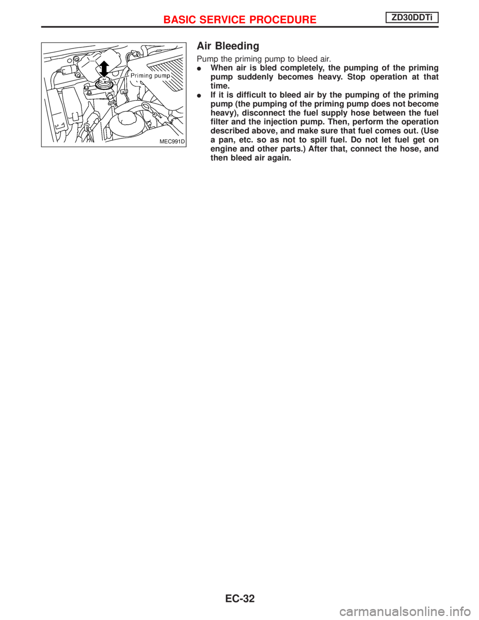
Pump the priming pump to bleed air.
IWhen air is bled completely, the pumping of the priming
pump suddenly becomes heavy. Stop operation at that
time.
IIf it is difficult to bleed air by the pumping of the priming
pump (the pumping of the priming pump does not become
heavy), disconnect the fuel supply hose between the fuel
filter and the injection pump. Then, perform the operation
described above, and make sure that fuel comes out. (Use
a pan, etc. so as not to spill fuel. Do not let fuel get on
engine and other parts.) After that, connect the hose, and
then bleed air again.
MEC991D
BASIC SERVICE PROCEDUREZD30DDTi
EC-32
Page 413 of 1767
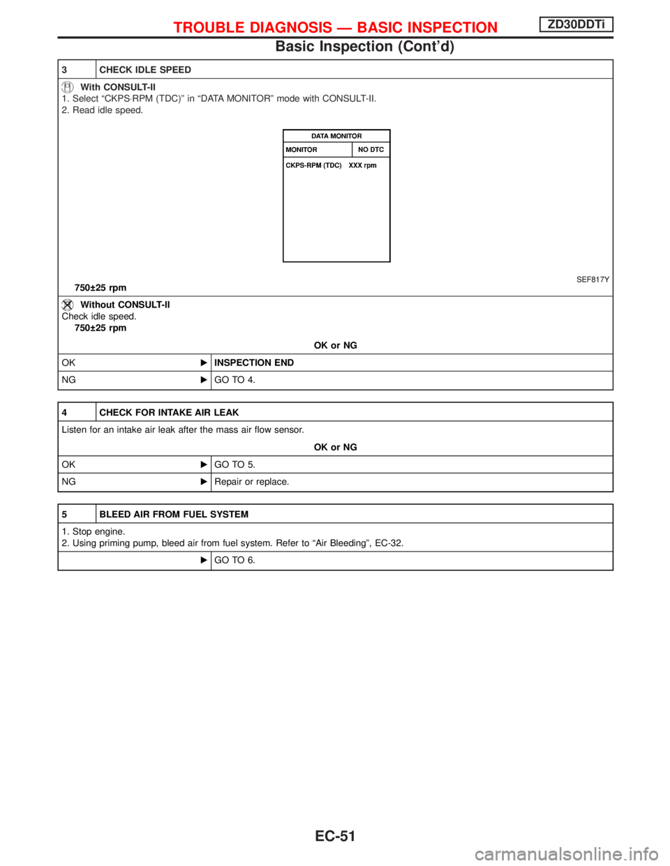
3 CHECK IDLE SPEED
With CONSULT-II
1. Select ªCKPS×RPM (TDC)º in ªDATA MONITORº mode with CONSULT-II.
2. Read idle speed.
SEF817Y750 25 rpm
Without CONSULT-II
Check idle speed.
750 25 rpm
OK or NG
OKEINSPECTION END
NGEGO TO 4.
4 CHECK FOR INTAKE AIR LEAK
Listen for an intake air leak after the mass air flow sensor.
OK or NG
OKEGO TO 5.
NGERepair or replace.
5 BLEED AIR FROM FUEL SYSTEM
1. Stop engine.
2. Using priming pump, bleed air from fuel system. Refer to ªAir Bleedingº, EC-32.
EGO TO 6.
TROUBLE DIAGNOSIS Ð BASIC INSPECTIONZD30DDTi
Basic Inspection (Cont'd)
EC-51
Page 559 of 1767
Diagnostic Procedure
1 INSPECTION START
1. Turn ignition switch ªOFFº.
2. Perform ªAir Bleedingº, EC-32, and ªDRAINING WATERº in MA section.
EGO TO 2.
2 PERFORM DTC CONFIRMATION PROCEDURE AGAIN
Perform ªDTC Confirmation Procedureº, EC-194 again.
OK or NG
OKEINSPECTION END
NGEGO TO 3.
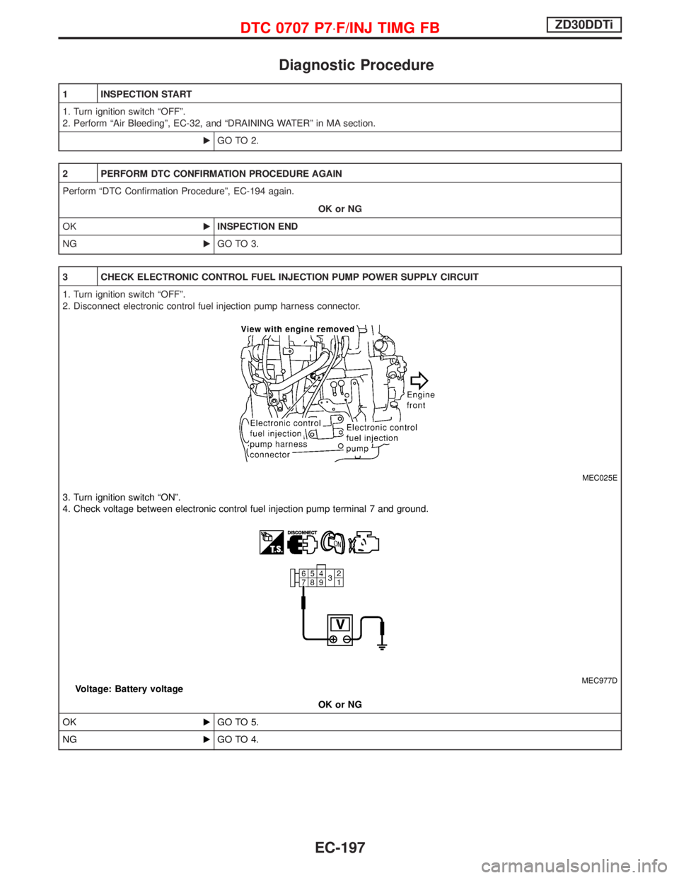
3 CHECK ELECTRONIC CONTROL FUEL INJECTION PUMP POWER SUPPLY CIRCUIT
1. Turn ignition switch ªOFFº.
2. Disconnect electronic control fuel injection pump harness connector.
MEC025E
3. Turn ignition switch ªONº.
4. Check voltage between electronic control fuel injection pump terminal 7 and ground.
MEC977DVoltage: Battery voltage
OK or NG
OKEGO TO 5.
NGEGO TO 4.
DTC 0707 P7×F/INJ TIMG FBZD30DDTi
EC-197