2002 NISSAN TERRANO air bleeding
[x] Cancel search: air bleedingPage 1419 of 1767
A
ABS (anti-lock brake system).........................BR-35
ABS - Wiring diagram ....................................BR-50
A/C air flow .......................................................HA-8
A/C compressor precaution..............................HA-5
A/C control operation (manual A/C) .................HA-6
A/C relay.........................................................HA-61
A/C symptom chart (manual A/C) ..................HA-36
A/C trouble diagnoses (manual A/C) .............HA-27
A/C, M - Wiring diagram ................................HA-43
ACC/SW - Wiring diagram ...........................EC-106
Accelerator control system ...........................FE-2, 5
Accelerator position sensor .........EC-130, 368, 371
Accelerator position switch ..................EC-369, 371
Accelerator switch (F/C) ...............................EC-104
Accelerator wire adjustment .............................FE-5
Accelerator work unit....................................EC-365
A/CCUT - Wiring diagram ............................EC-289
Air bag ..............................................................RS-6
Air bag disposal..............................................RS-20
Air bag precautions ...........................................GI-3
Air bleeding (hydraulic clutch) ..........................CL-6
Air bleeding for brake system ..........................BR-8
Air cleaner filter replacement ..............MA-5, 20, 24
Air conditioner cut control ..............EC-22, 311, 440
Air control cable adjustment...........................HA-62
Air flow meter - See Mass air flow
sensor .................................................EC-88, 356
Alternator ........................................................SC-27
Angular tightening application..........................EM-3
Antenna .................................................EL-111, 127
Anti-lock brake system - See ABS .................BR-37
Anti-lock brake system - Wiring
diagram .......................................................BR-50
APS - Wiring diagram ..................................EC-133
ASCD vacuum hose ......................................MA-40
A/T - Wiring diagram .........................................AT-7
A/T - Wiring diagram - AT - PNP/SW .............AT-87
A/T - Wiring diagram - AT - VSS A/T ..............AT-49
A/T control ....................................................EC-155
A/T diagnosis communication line ...............EC-155
A/T fluid checking ............................................AT-27
A/T fluid temperature sensor...........................AT-76
A/T mode switch..............................................AT-94
A/T self-diagnoses ....................................AT-14, 19
A/T Wiring diagram - AT - ENG SS ................AT-79
A/T Wiring diagram AT - BA/FTS ....................AT-75
A/T Wiring diagram AT - LPSV .......................AT-82
A/T Wiring diagram AT - OVRCSV .................AT-68
A/T Wiring diagram AT - SSV/A ......................AT-62
A/T Wiring diagram AT - SSV/B ......................AT-65
A/T Wiring diagram AT - TCV .........................AT-71
A/T Wiring diagram AT - TPS..........................AT-56
A/T Wiring diagram AT - VSSMTR .................AT-52
AT/C - Wiring diagram..................................EC-157
Audio......................................................EL-111, 113
AUDIO - Wiring diagram ...............................EL-115Audio and A/C control removal and
installation - See Instrument panel .............BT-16
Auto lock free running hub .............................FA-14
Automatic transmission number ......................GI-30
Axle housing (rear) ...........................................RA-8
B
Back Door .......................................................BT-14
Back door opener - See Back door ................BT-14
Back door trim.................................................BT-18
Back door window...........................................BT-43
Back-up lamp ..................................................EL-49
Back-up lamp switch (M/T) ........................MT-6, 10
BACK/L - Wiring diagram................................EL-49
Ball joint front axle ..........................................FA-36
Basic inspection .....................................EC-50, 338
Battery ..............................................................SC-3
Battery Voltage .............................................EC-153
Blower motor ..................................................HA-60
Blower resistor................................................HA-60
Body alignment ...............................................BT-49
BOOST - Wiring diagram .............................EC-217
Boring/horning cylinder block.........................EM-74
Brake booster .................................................BR-17
Brake fluid change ...........................................BR-5
Brake fluid level ...........................MA-17, 36, 40, 43
Brake fluid level and line check .......................BR-5
Brake hydraulic line......................................BR-5, 6
Brake inspection ..........................MA-36, 40, 41, 42
Brake lines and cables inspection.....MA-36, 40, 42
Brake lining wear temporary checking ....MA-36, 42
Brake master cylinder ....................................BR-16
Brake pedal ....................................................BR-14
Brake switch .................................................EC-400
BRK/SW - Wiring diagram ...........................EC-205
Bumper, front ....................................................BT-6
Bumper, rear .....................................................BT-8
C
Camshaft ........................................................EM-30
Camshaft position sensor (PUMP)...............EC-161
Center case (Transfer) ......................................TF-9
CHARGE - Wiring diagram ............................SC-24
Charge air pressure sensor .........................EC-215
Charging system ............................................SC-23
Chassis and body maintenance ....................MA-36
CIGAR - Wiring diagram ...............................EL-105
Cigarette lighter.............................................EL-104
Circuit breaker.................................................EL-17
CKPS - Wiring diagram ................................EC-147
Clock .............................................................EL-104
CLOCK - Wiring diagram ..............................EL-106
Clutch cover ..............................................CL-11, 12
Clutch disc ......................................................CL-11
Clutch fluid level ......................................MA-17, 36
Clutch master cylinder ..................................CL-7, 8
ALPHABETICAL INDEX
IDX-2
Page 1422 of 1767
INT/V - Wiring diagram ................................EC-274
Intake air control valve control solenoid
valve .........................................................EC-273
Intake Air Volume .........................................EC-143
Intake door control linkage adjustment ..........HA-63
Intake manifold...............................................EM-12
Interior .............................................................BT-18
Interior lamp ..............................................EL-61, 66
ISO 15031-2 Terminology................................GI-35
K
Knuckle spindle ...............................................FA-20
L
License lamp ...................................................EL-45
Limited slip diff. adjustment............................PD-45
Limited slip diff. assembly ..............................PD-47
Limited slip diff. disassembly ...................PD-43, 44
Limited slip diff. inspection .............................PD-44
Line pressure solenoid valve ..........................AT-84
Line pressure test (A/T) ..........................AT-30, 196
Liquid gasket application .................................EM-3
Location of electrical units ............EL-241, 242, 244
Lock, door ...........................................BT-10, 12, 14
Low and reverse brake .................................AT-161
LSV (Load sensing valve) ..............................BR-10
Lubricants.......................................................MA-17
Lubrication circuit (engine) .........................LC-3, 20
Lubrication oil A/C ....................................HA-22, 64
Lubrication-locks, hinges and hood
latches ..................................................MA-36, 45
Luggage compartment trim .............................BT-18
M
MAFS - Wiring diagram..................................EC-90
MAIN - Wiring diagram...................................EC-80
Main drive gear (M/T) .....................................MT-11
Main gear (Transfer) .................................TF-10, 21
Mainshaft (M/T) ..............................................MT-11
Mainshaft (Transfer)..................................TF-10, 17
Maintenance ...........MA-5, 8, 11, 14, 20, 36, 48, 49
MAJOR OVERHALL ......................................AT-119
Major overhaul (Transfer) .................................TF-9
Malfunction indicator (MI).......................EC-34, 322
Manifold tightening torque (intake &
exhaust) ...............................................MA-20, 28
Manual transmission number ..........................GI-30
Manual transmission oil replacement ......MA-36, 37
Map lamp ........................................................EL-66
Mass air flow sensor (MAFS) ................EC-88, 356
Master cylinder (brake) ..................................BR-16
Meter .........................................................EL-70, 71
METER - Wiring diagram................................EL-72
MIL/DL - Wiring diagram ..............................EC-291MIRROR - Wiring diagram............................EL-131
Mirror, door......................................................BT-48
Model variation ................................................GI-28
Molding - See Exterior ....................................BT-21
M/T major overhaul ........................................MT-10
M/T removal and installation ........................MT-7, 8
Mud guard - See Exterior ...............................BT-21
MULTI - Wiring diagram................................EL-169
Multi-remote control system .........EL-168, 177, 179
Multiport fuel injection precautions ....................GI-5
N
NATS (Nissan anti-theft
system) .....................EL-186, 187, 188, 195, 208
NATS - Wiring diagram .................................EL-189
NATS V2.0 precautions (For Europe) ...............GI-4
Needle lift sensor .........................................EC-427
NVH troubleshooting (EM) ...............................EM-8
O
Oil change (capacity) ............MA-21, 29, 37, 38, 39
Oil change (interval) ..................................MA-5, 35
Oil cooler (engine) ............................................LC-8
Oil pan (engine) .............................................EM-22
Oil pump (A/T)...............................................AT-134
Oil seal replacement (engine)........................EM-50
Oil seal replacement (front final drive
4WD)...........................................................PD-10
OILPSW - Wiring diagram............................EC-451
On board diagnostic system ..................EC-33, 321
Overdrive control switch..................................AT-95
Overheat .......................................................EC-109
Overrun clutch solenoid valve ..................AT-69, 70
Oversize piston ..............................................EM-74
P
Park/Neutral position switch .........................EC-251
Park/neutral position switch (A/T) ...........AT-88, 114
Parking drum brake ........................................BR-35
Parking lamp ...................................................EL-45
PCV (positive crankcase ventilation) .....EC-23, 312
Periodic maintenance ......................................MA-5
Piston pin inspection ......................................EM-71
Piston ring inspection.....................................EM-72
PNP/SW - Wiring diagram ...........................EC-252
POWER - Wiring diagram.................................EL-8
Power door lock ...EL-137, 138, 145, 146, 148, 158
Power steering fluid level...............MA-36, 44, ST-4
Power steering gear .................................ST-12, 22
Power steering hydraulic pressure ...................ST-7
Power steering oil pump ...........................ST-16, 22
Power steering system bleeding.......................ST-5
Power supply routing ....................................EL-6, 8
Power window ...............................................EL-133
ALPHABETICAL INDEX
IDX-5
Page 1483 of 1767
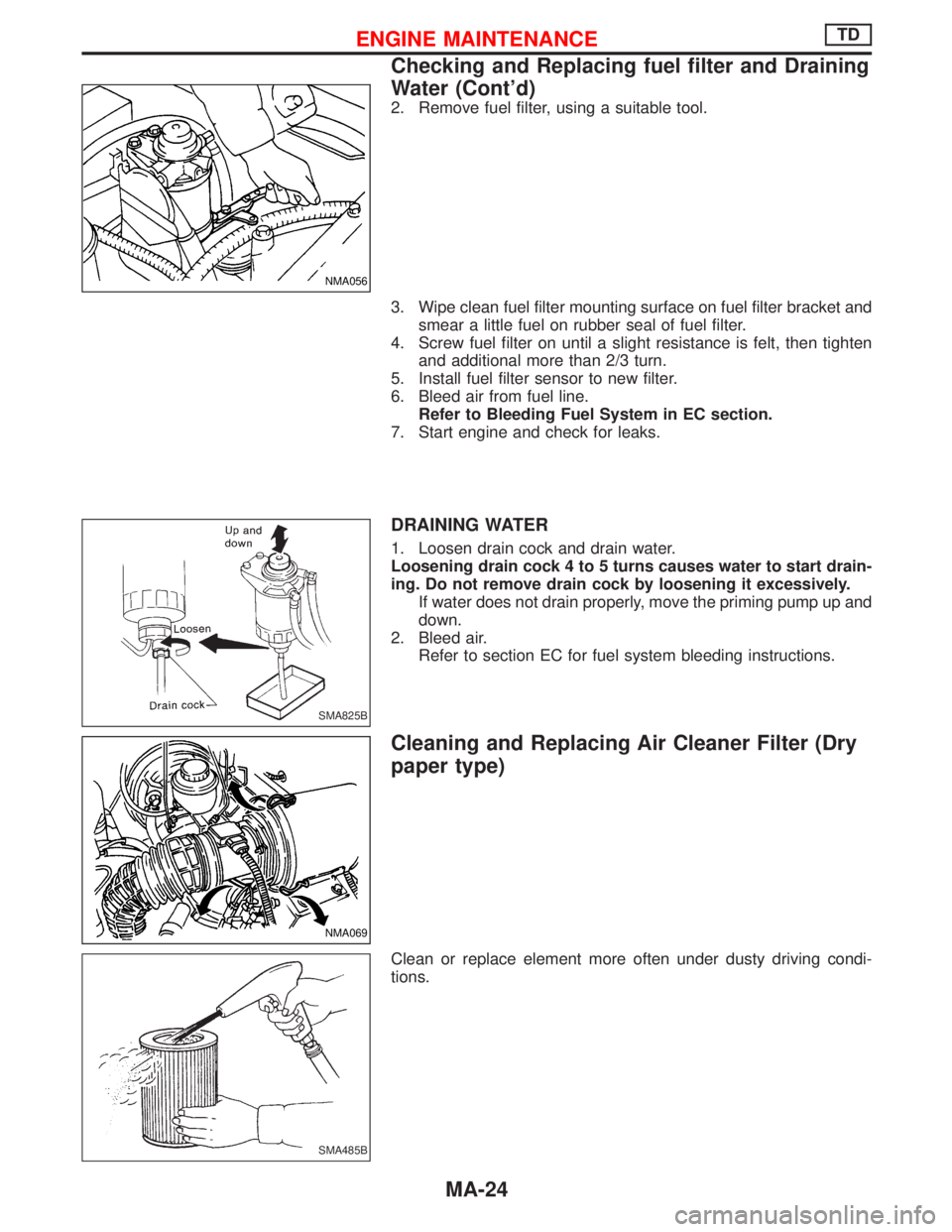
2. Remove fuel filter, using a suitable tool.
3. Wipe clean fuel filter mounting surface on fuel filter bracket and
smear a little fuel on rubber seal of fuel filter.
4. Screw fuel filter on until a slight resistance is felt, then tighten
and additional more than 2/3 turn.
5. Install fuel filter sensor to new filter.
6. Bleed air from fuel line.
Refer to Bleeding Fuel System in EC section.
7. Start engine and check for leaks.
DRAINING WATER
1. Loosen drain cock and drain water.
Loosening drain cock 4 to 5 turns causes water to start drain-
ing. Do not remove drain cock by loosening it excessively.
If water does not drain properly, move the priming pump up and
down.
2. Bleed air.
Refer to section EC for fuel system bleeding instructions.
Cleaning and Replacing Air Cleaner Filter (Dry
paper type)
Clean or replace element more often under dusty driving condi-
tions.
NMA056
SMA825B
NMA069
SMA485B
ENGINE MAINTENANCETD
Checking and Replacing fuel filter and Draining
Water (Cont'd)
MA-24
Page 1493 of 1767
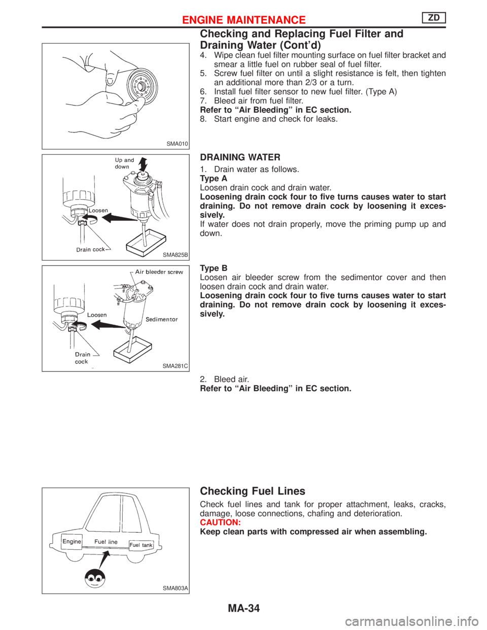
4. Wipe clean fuel filter mounting surface on fuel filter bracket and
smear a little fuel on rubber seal of fuel filter.
5. Screw fuel filter on until a slight resistance is felt, then tighten
an additional more than 2/3 or a turn.
6. Install fuel filter sensor to new fuel filter. (Type A)
7. Bleed air from fuel filter.
Refer to ªAir Bleedingº in EC section.
8. Start engine and check for leaks.
DRAINING WATER
1. Drain water as follows.
Type A
Loosen drain cock and drain water.
Loosening drain cock four to five turns causes water to start
draining. Do not remove drain cock by loosening it exces-
sively.
If water does not drain properly, move the priming pump up and
down.
Type B
Loosen air bleeder screw from the sedimentor cover and then
loosen drain cock and drain water.
Loosening drain cock four to five turns causes water to start
draining. Do not remove drain cock by loosening it exces-
sively.
2. Bleed air.
Refer to ªAir Bleedingº in EC section.
Checking Fuel Lines
Check fuel lines and tank for proper attachment, leaks, cracks,
damage, loose connections, chafing and deterioration.
CAUTION:
Keep clean parts with compressed air when assembling.
SMA010
SMA825B
SMA281C
SMA803A
ENGINE MAINTENANCEZD
Checking and Replacing Fuel Filter and
Draining Water (Cont'd)
MA-34
Page 1502 of 1767
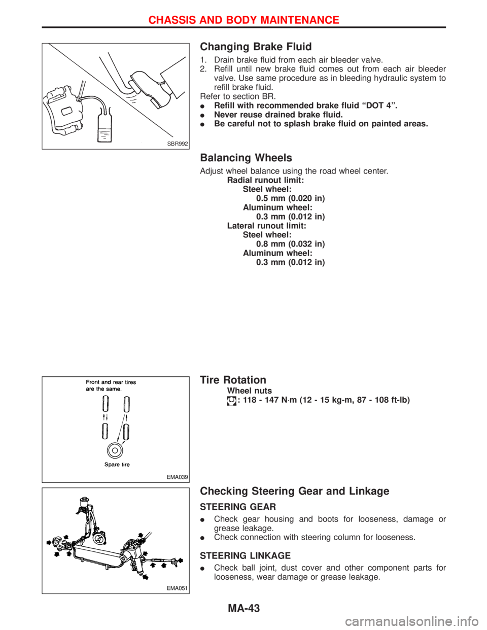
Changing Brake Fluid
1. Drain brake fluid from each air bleeder valve.
2. Refill until new brake fluid comes out from each air bleeder
valve. Use same procedure as in bleeding hydraulic system to
refill brake fluid.
Refer to section BR.
IRefill with recommended brake fluid ªDOT 4º.
INever reuse drained brake fluid.
IBe careful not to splash brake fluid on painted areas.
Balancing Wheels
Adjust wheel balance using the road wheel center.
Radial runout limit:
Steel wheel:
0.5 mm (0.020 in)
Aluminum wheel:
0.3 mm (0.012 in)
Lateral runout limit:
Steel wheel:
0.8 mm (0.032 in)
Aluminum wheel:
0.3 mm (0.012 in)
Tire Rotation
Wheel nuts
: 118 - 147 N×m (12 - 15 kg-m, 87 - 108 ft-lb)
Checking Steering Gear and Linkage
STEERING GEAR
ICheck gear housing and boots for looseness, damage or
grease leakage.
ICheck connection with steering column for looseness.
STEERING LINKAGE
ICheck ball joint, dust cover and other component parts for
looseness, wear damage or grease leakage.
SBR992
EMA039
EMA051
CHASSIS AND BODY MAINTENANCE
MA-43
Page 1712 of 1767
STEERING SYSTEM
SECTION
ST
CONTENTS
PRECAUTIONS...............................................................2
Supplemental Restraint System (SRS)²AIR
BAG²and²SEAT BELT PRE-TENSIONER²
(Dual Air Bag System) .................................................2
Precautions for Steering System .................................2
PREPARATION................................................................3
Special Service Tools ..................................................3
ON-VEHICLE SERVICE..................................................4
Checking Steering Wheel Play ....................................4
Checking Neutral Position on Steering Wheel ............4
Front Wheel Turning Angle ..........................................4
Checking and Adjusting Drive Belts ............................4
Checking Fluid Level ...................................................4
Checking Fluid Leakage ..............................................5
Bleeding Hydraulic System..........................................5
Checking Steering Wheel Turning Force ....................6
Checking Hydraulic System.........................................7STEERING WHEEL AND STEERING COLUMN............8
Removal and Installation .............................................8
Disassembly and Assembly .......................................10
Inspection................................................................... 11
POWER STEERING GEAR...........................................12
Description .................................................................12
Removal and Installation ...........................................14
Inspection and Adjustment ........................................15
POWER STEERING OIL PUMP....................................16
Removal and Installation ...........................................16
STEERING LINKAGE....................................................17
Removal and Installation ...........................................17
Disassembly and Assembly .......................................19
Inspection...................................................................20
SERVICE DATA AND SPECIFICATIONS (SDS)..........22
General Specifications ...............................................22
Inspection and Adjustment ........................................22
Page 1716 of 1767
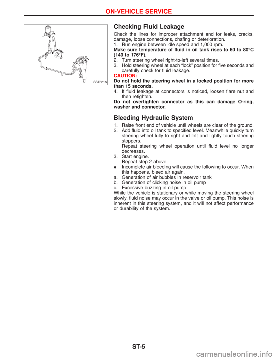
Checking Fluid Leakage
Check the lines for improper attachment and for leaks, cracks,
damage, loose connections, chafing or deterioration.
1. Run engine between idle speed and 1,000 rpm.
Make sure temperature of fluid in oil tank rises to 60 to 80ÉC
(140 to 176ÉF).
2. Turn steering wheel right-to-left several times.
3. Hold steering wheel at each ªlockº position for five seconds and
carefully check for fluid leakage.
CAUTION:
Do not hold the steering wheel in a locked position for more
than 15 seconds.
4. If fluid leakage at connectors is noticed, loosen flare nut and
then retighten.
Do not overtighten connector as this can damage O-ring,
washer and connector.
Bleeding Hydraulic System
1. Raise front end of vehicle until wheels are clear of the ground.
2. Add fluid into oil tank to specified level. Meanwhile quickly turn
steering wheel fully to right and left and lightly touch steering
stoppers.
Repeat steering wheel operation until fluid level no longer
decreases.
3. Start engine.
Repeat step 2 above.
IIncomplete air bleeding will cause the following to occur. When
this happens, bleed air again.
a. Generation of air bubbles in reservoir tank
b. Generation of clicking noise in oil pump
c. Excessive buzzing in oil pump
While the vehicle is stationary or while moving the steering wheel
slowly, fluid noise may occur in the valve or oil pump. This noise is
inherent in this steering system, and it will not affect performance
or durability of the system.
SST621A
ON-VEHICLE SERVICE
ST-5