Page 88 of 385
85 Instrument cluster
Te ch n i c a l
data Instruments
and controlsOperationDrivingInstrument
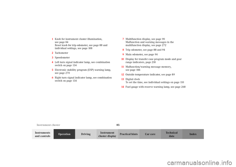
cluster displayPractical hints Car care Index 1Knob for instrument cluster illumination,
seepage84
Reset knob for trip odometer, see page 88 and
individual settings, see page 108
2Tachometer
3Speedometer
4Left turn signal indicator lamp, see combination
switch on page 134
5Electronic stability program (ESP) warning lamp,
see page 270
6Right turn signal indicator lamp, see combination
switch on page 1347Multifunction display, see page 90
Malfunction and warning messages in the
multifunction display, see page 272
8Trip odometer, see page 88 and 94
9Main odometer, see page 94
10Display for transfer case program mode and gear
range indicators, page 210
11Malfunction/warning message memory,
seepage106
12Outside temperature indicator, see page 89
13Digital clock
To set the time, see individual settings on page 110
14Fuel gauge with reserve warning lamp, see page 268
J_G463.book Seite 85 Mittwoch, 19. September 2001 8:06 08
Page 90 of 385
87 Instrument cluster
Te ch n i c a l
data Instruments
and controlsOperationDrivingInstrument
cluster displayPractical hints Car care Index Activating instrument cluster display
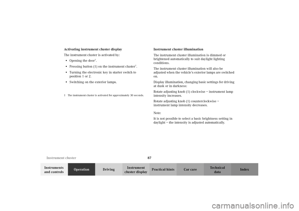
The instrument cluster is activated by:
•Opening the door
1.
•Pressing button (1) on the instrument cluster
1.
•Turning the electronic key in starter switch to
position 1 or 2.
•Switching on the exterior lamps.
1 The instrument cluster is activated for approximately 30 seconds.
Instrument cluster illumination
The instrument cluster illumination is dimmed or
brightened automatically to suit daylight lighting
conditions.
The instrument cluster illumination will also be
adjusted when the vehicle’s exterior lamps are switched
on.
Display illumination, changing basic settings for driving
at dusk or in darkness:
Rotate adjusting knob (1) clockwise – instrument lamp
intensity increases.
Rotate adjusting knob (1) counterclockwise –
instrument lamp intensity decreases.
Note:
It is not possible to select a basic brightness setting in
daylight – the intensity is adjusted automatically.
J_G463.book Seite 87 Mittwoch, 19. September 2001 8:06 08
Page 114 of 385
111 Multifunction steering wheel, multifunction display
Te ch n i c a l
data Instruments
and controlsOperationDrivingInstrument
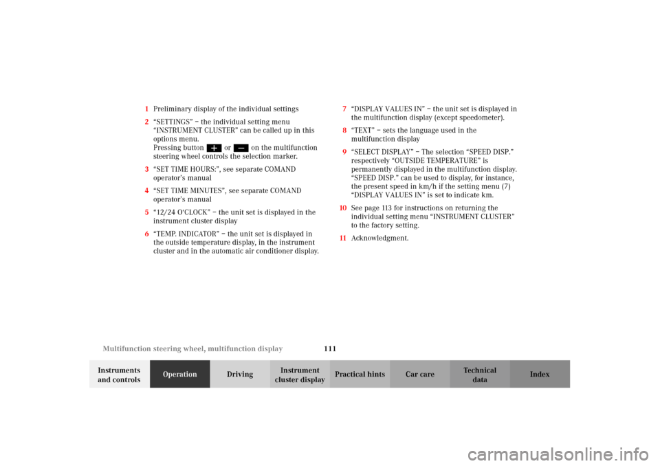
cluster displayPractical hints Car care Index 1Preliminary display of the individual settings
2“SETTINGS” – the individual setting menu
“INSTRUMENT CLUSTER” can be called up in this
options menu.
Pressing buttonæ orç on the multifunction
steering wheel controls the selection marker.
3“SET TIME HOURS:”, see separate COMAND
operator’s manual
4“SET TIME MINUTES”, see separate COMAND
operator’s manual
5“12/24 O‘CLOCK” – the unit set is displayed in the
instrument cluster display
6“TEMP. INDICATOR” – the unit set is displayed in
the outside temperature display, in the instrument
cluster and in the automatic air conditioner display.7“DISPLAY VALUES IN” – the unit set is displayed in
the multifunction display (except speedometer).
8“TEXT” – sets the language used in the
multifunction display
9“SELECT DISPLAY” – The selection “SPEED DISP.”
respectively “OUTSIDE TEMPERATURE” is
permanently displayed in the multifunction display.
“SPEED DISP.” can be used to display, for instance,
the present speed in km/h if the setting menu (7)
“DISPLAY VALUES IN” is set to indicate km.
10See page 113 for instructions on returning the
individual setting menu “INSTRUMENT CLUSTER”
to the factory setting.
11Acknowledgment.
J_G463.book Seite 111 Mittwoch, 19. September 2001 8:06 08
Page 209 of 385
206 Starting and turning off the engine
Te ch n i c a l
data Instruments
and controlsOperationDrivingInstrument
cluster displayPractical hints Car care Index
Starting and turning off the engine
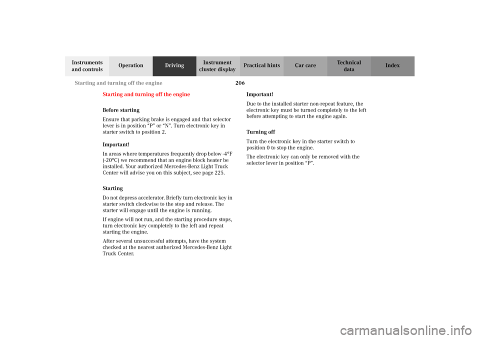
Before starting
Ensure that parking brake is engaged and that selector
lever is in position “P” or “N”. Turn electronic key in
starter switch to position 2.
Important!
In areas where temperatures frequently drop below -4
°F
(-20
°C) we recommend that an engine block heater be
installed. Your authorized Mercedes-Benz Light Truck
Center will advise you on this subject, see page 225.
Starting
Do n ot de pr ess accelerato r. B rie f ly turn electron ic key in
starter switch clockwise to the stop and release. The
starter will engage until the engine is running.
If engine will not run, and the starting procedure stops,
turn electronic key completely to the left and repeat
starting the engine.
After several unsuccessful attempts, have the system
checked at the nearest authorized Mercedes-Benz Light
Truck Center.Important!
Due to the installed starter non-repeat feature, the
electronic key must be turned completely to the left
before attempting to start the engine again.
Turning off
Turn the electronic key in the starter switch to
position 0 to stop the engine.
The electronic key can only be removed with the
selector lever in position “P”.
J_G463.book Seite 206 Mittwoch, 19. September 2001 8:06 08
Page 312 of 385
309 Spare wheel, vehicle jack
Te ch n i c a l
data Instruments
and controlsOperation DrivingInstrument
cluster displayPractical hintsCar care Index Insert pump handle in direction of arrow.Do not turn release bolt (5) more than two turns
counterclockwise when lowering vehicle, otherwise
hydraulic fluid may leak out from jack.
Note:
After use, disassemble pump handle and store with jack
in the designated storage compartment below the rear
seat bench.
J_G463.book Seite 309 Mittwoch, 19. September 2001 8:06 08
Page 323 of 385
320 Battery
Te ch n i c a l
data Instruments
and controlsOperation DrivingInstrument
cluster displayPractical hintsCar care Index
The service life of the battery is dependent on its
condition of charge. The battery should always be kept
sufficiently charged, in order to last an optimum length
of time.
Therefore, we strongly recommend that you have the
battery charge checked frequently, and corrected if
necessary, especially if you use the vehicle less than
approximately 200 miles (300 km) per month,
mostly for short distance trips, or if it is not used for
long periods of time.
Only charge a battery with a battery charger after the
battery has been disconnected from the vehicle’s
electrical circuit.
Always disconnect the battery negative lead first and
connect last.
When removing and connecting the battery, always
make sure that all electrical consumers are off and the
key is in starter switch position 0. The battery must
always be securely installed when the vehicle is in
operation. During removal and installation always
protect the disconnected battery positive (+) terminal
with the cover attached to the battery.While t he en gin e is run ning t he batter y te rm in al clamp s
must not be loosened or detached, otherwise the
generator and other electronic components would be
damaged.
Note:
The gear selector lever will remain locked in
position “P” and the electronic key can not be turned in
the starter switch, if the vehicle battery is disconnected
or discharged.
After reconnecting the battery also set the clock (see
COMAND operator’s manual), synchronize the
electronic stability program (ESP) (see page 244) and
the front seat head restraints (see page 47).
Battery recycling
Batteries contain material that can harm the
environment with improper disposal.
Large 12 Volt storage batteries contain lead.
Recycling of batteries is the preferred method of
disposal.
Many states require sellers of batteries to accept old
batteries for recycling.
J_G463.book Seite 320 Mittwoch, 19. September 2001 8:06 08
Page 334 of 385
331 Exterior lamps
Te ch n i c a l
data Instruments
and controlsOperation DrivingInstrument
cluster displayPractical hintsCar care Index Bulbs for low and high beam
H4 60 / 55W 12V
Remove protection cover (5) and pull off electrical
connector (6).
Unclip retainer spring (8) and take out bulb (9).
Insert new bulb so that the base locates in the recess on
the holder.
Clip in retainer spring (8), plug the electrical
connector (6) onto the bulb (9) and press on protection
cover (5).
Bulbs for parking and standing lamp
T 4W 12V
Pull off electrical connector (6) from the bulb (10).
Push bulb (10) into socket, turn counterclockwise and
remove.
Insert new bulb (10) in socket, push in and turn
clockwise until it clicks in.
Plug electrical connector (6) onto the bulb (10).To reinstall headlamp:
Insert headlamp (3) and screw in headlamp-securing
screws (4).
Install head lamp trim panel (2) and seal and screw in
securing screws (1).
J_G463.book Seite 331 Mittwoch, 19. September 2001 8:06 08
Page 337 of 385
334 Exterior lamps
Te ch n i c a l
data Instruments
and controlsOperation DrivingInstrument
cluster displayPractical hintsCar care Index
Turn signal lamp, front
1Securing screw
2Turn signal lens
3Bulb for turn signal lamp
PY 21W 12V (1156NA[cp 32])Unscrew securing screws (1) and remove turn signal
lens (2).
Push bulb (3) into socket, turn counterclockwise and
remove.
Insert new bulb (3) in socket, push in and turn
clockwise until it clicks in.
Install turn signal lens (2) and screw in securing
screws (1).
Do not overtighten the securing screws, as this could
cause the turn signal lens to break.
J_G463.book Seite 334 Mittwoch, 19. September 2001 8:06 08