2002 MERCEDES-BENZ G500 wheel torque
[x] Cancel search: wheel torquePage 232 of 385
229 Driving instructions
Te ch n i c a l
data Instruments
and controlsOperationDrivingInstrument
cluster displayPractical hints Car care Index Traction in steep terrain:
Be easy on the accelerator and watch for continuous
wheel traction when driving in steep terrain.
When the differential locks are not engaged, 4-ETS
helps greatly when starting out on a steep incline. The
front wheels have then the tendency to slip due to the
weight reduction over the front axle. The ETS
recognizes the situation and limits the torque for the
front wheels by braking them. Simultaneously the
torque for the rear wheels is increased.
See page 241 for four wheel electronic traction system
(4-ETS).
Driving across a hilltop:
To prevent the vehicle from speeding up too much after
climbing a hill, decelerate just ahead of a hilltop (do not
select gear range “N”). Use the momentum of the
vehicle to drive across the hilltop. Driving in this
manner prevents the vehicle from jumping across the
hilltop and thus loosing its forward momentum.
Driving downhill:
Select gear range “1” on the automatic transmission,
see page 207.Drive downhill observing the same rules as driving
uphill.
Driving on embankments, slopes and other steep
inclines should only be done straight up or downhill, i.e.
in the line of gravity.
Do not drive along the side of a slope (danger of vehicle
rollover). If in doing so, the vehicle begins to show a
tendency to roll, immediately steer into a line of gravity
(straight up or downhill).
Utilize the engine’s braking power when descending a
slope, observe the engine speed (do not overrev the
engine). Apply the service brake as needed.
The special LOW range ABS setting allows for precise
and brief (cyclical) blocking of the front wheels,
permitting them to dig into loose ground. Remember
that the front wheels when stopped, slide across a
surface, thus loose their ability to steer the vehicle.
Check the brakes after a lengthy downgrade drive.
Important!
Only apply the service brake if the vehicle travels
straight downhill, i.e. in the line of gravity.
J_G463.book Seite 229 Mittwoch, 19. September 2001 8:06 08
Page 246 of 385
243 Driving systems
Te ch n i c a l
data Instruments
and controlsOperationDrivingInstrument
cluster displayPractical hints Car care Index Electronic stability program (ESP)
The ESP enhances directional control and reduces
driving wheel spin of the vehicle under various driving
conditions.
Over-/understeering of the vehicle is counteracted by
applying brakes to the appropriate wheel to create a
countervailing vehicle movement. Engine torque is also
limited. The ESP warning lamp, located in the
speedometer dial, starts to flash when ESP is in
operation.Important!
If the ESP warning lampv flashes:
•During take-off apply as little throttle as possible.
•While driving ease up on the accelerator.
•Adapt your speed and driving to the prevailing road
conditions.
•Do not switch off the ESP.
Caution!
If the vehicle is towed with the front axle raised (see
towing the vehicle on page 324), the engine must be
shut off (electronic key in starter switch position 0 or 1).
Otherwise, the ESP will immediately be engaged and
will apply the rear wheel brakes.
Notes:
The yellow ESP warning lampv in the speedometer
dial comes on with the electronic key in starter switch
position 2. They should go out with the engine running.
Wa r n i n g !
ESP cannot prevent the natural laws of physics
from acting on the vehicle, nor can it increase the
traction afforded. The ESP cannot prevent
ac c id ent s, i nc l udi ng t hose resul tin g from exc es si ve
speed in turns, or aquaplaning. Only a safe,
attentive, and skillful driver can prevent accidents.
The capabilities of an ESP equipped vehicle must
never be exploited in a reckless or dangerous
manner which could jeopardize the user’s safety or
the safety of others.
J_G463.book Seite 243 Mittwoch, 19. September 2001 8:06 08
Page 254 of 385
251 Driving systems
Te ch n i c a l
data Instruments
and controlsOperationDrivingInstrument
cluster displayPractical hints Car care Index A few words about differentials and differential
locks
When a vehicle negotiates a turn, wheels on the outside
of the curve must travel farther and rotate faster than
the inside wheels. The differential, the operation of a set
of gears that allow the powered wheels in a vehicle to
turn a different speeds, provides for this essential
function.
The drawback is that the differential also sends most of
the engine's power to the wheel with the least load or
strain on it. For example, if one of a vehicle's powered
wheels sits on a patch of snow and spins because there
is no traction, all of the engine's power will go to that
wheel because the power will take the path of least
resistance. Meanwhile, the opposite wheel, sitting on
dry pavement where it could get enough grip to start the
vehicle moving, sits idle because it gets no power.
The Electronic Traction System (ETS) addresses this
problem and provides for good control and steering
ability by automatically slowing the slipping wheel and
thus increasing the power to the other non-slipping
d rive whee ls to get t he ve hicle m ovin g. The ESP and ETS
in this vehicle feature such intelligent limited-slip
differential technology, ideally suited for on-road and light off-road driving. The position “LOW” of the
transfer case (see pages 247and 226) also enhances
off-road driving capabilities.
More extreme off-road conditions may call for another
cure which is to engage a differential lock, preventing
the differential from operating altogether. This vehicle
offers as standard equipment three differential locks:
front, transfer case (center), and rear. Each can be
engaged simply by pushing a dashboard-mounted
button (see pages 253 and 254 for engaging differential
locks). When the transfer case (center) differential is
locked, half of the engine's power is automatically
distributed to the front wheels and half to the rear
wheels. When the rear differential is locked, power
going to the rear wheels is equally distributed, so that
both rear wheels turn at the same speed and torque.
When the front differential is locked, all four wheels
now turn with equal power and torque. Please be aware
that engaging the differential locks will significantly
reduce steering ability of the vehicle.
J_G463.book Seite 251 Mittwoch, 19. September 2001 8:06 08
Page 313 of 385

310 Tires, Wheels
Te ch n i c a l
data Instruments
and controlsOperation DrivingInstrument
cluster displayPractical hintsCar care Index
Wheels
Replace rims or tires with the same designation,
manufacturer and type as shown on the original part.
See your authorized Mercedes-Benz Light Truck Center
for further information.
See your authorized Mercedes-Benz Light Truck Center
for information on tested and recommended rims and
tires for summer and winter operation. They can also
offer advice concerning tire service and purchase.Tire replacement
Front and rear tires should be replaced in sets. Rims
and tires must be of the correct size and type. For
dimensions, see technical data on page 359.
We recommend that you break in new tires for
approximately 60 miles (100 km) at moderate speed.
It is imperative that the wheel mounting bolts be
fastened to a tightening torque of 97 ft.lb. (130 Nm)
whenever wheels are mounted.
For rim and tire specif ications, refer to technical data on
page 359.
Wa r n i n g !
Do not mix different tire construction types (i.e.
radial, bias, bias-belted) on your vehicle because
handling may be adversely affected and may result
in loss of control.
Wa r n i n g !
Worn, old tires can cause accidents. If the tire tread
is badly worn, or if the tires have sustained
damage, replace them.When replacing rims, use only genuine
Mercedes-Benz wheel bolts specified for the
particular rim type. Failure to do so can result in
the bolts loosening and possibly an accident.
J_G463.book Seite 310 Mittwoch, 19. September 2001 8:06 08
Page 320 of 385
317 Tires, Wheels
Te ch n i c a l
data Instruments
and controlsOperation DrivingInstrument
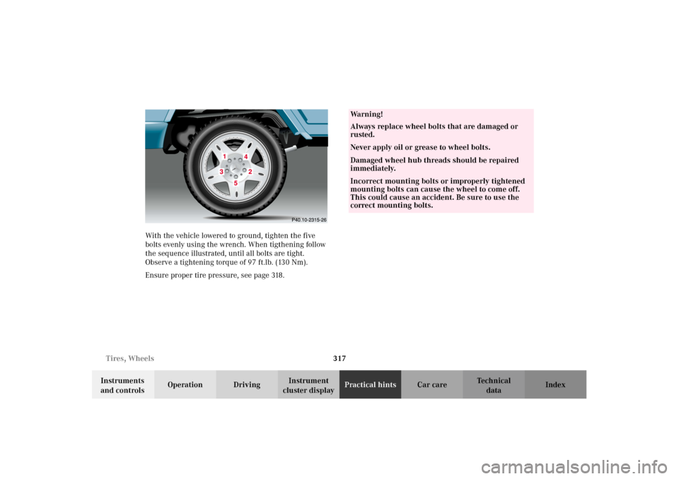
cluster displayPractical hintsCar care Index With the vehicle lowered to ground, tighten the five
bolts evenly using the wrench. When tigthening follow
the sequence illustrated, until all bolts are tight.
Observe a tightening torque of 97 ft.lb. (130 Nm).
Ensure proper tire pressure, see page 318.
Wa r n i n g !
Always replace wheel bolts that are damaged or
rusted.Never apply oil or grease to wheel bolts.Damaged wheel hub threads should be repaired
immediately.Incorrect mounting bolts or improperly tightened
mounting bolts can cause the wheel to come off.
This could cause an accident. Be sure to use the
correct mounting bolts.
J_G463.book Seite 317 Mittwoch, 19. September 2001 8:06 08
Page 362 of 385
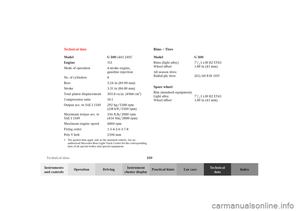
359 Technical data
Te ch n i c a l
data Instruments
and controlsOperation DrivingInstrument
cluster displayPractical hints Car care Index Te ch n i c a l d a t aRims – Tires
Model G 500 (463 249)
1
Engine113
Mode of operation 4-stroke engine,
gasoline injection
No. of cylinders 8
Bore 3.54 in (89.90 mm)
Stroke 3.31 in (84.00 mm)
Total piston displacement 303.0 cu.in. (4966 cm
3)
Compression ratio 10:1
Output acc. to SAE J 1349 292 hp / 5500 rpm
(218 kW / 5500 rpm)
Maximum torque acc. to
SAE J 1349336 ft.lb / 2800 rpm
(454 Nm / 2800 rpm)
Maximum engine speed 6000 rpm
Firing order 1-5-4-2-6-3-7-8
Poly-V-belt 2390 mm
1 The quoted data apply only to the standard vehicle. See an
authorized Mercedes-Benz Light Truck Center for the corresponding
data of all special bodies and special equipment.
Model G 500
Rims (light alloy)
Wheel offset7
1/2 J x18 H2 ET43
1.89 in (43 mm)
All season tires:
Radial-ply tires 265 / 60 R18 110V
Spare wheel
Rim (standard equipment)
Light alloy
Wheel offset7
1/2 J x18 H2 ET43
1.89 in (43 mm)
J_G463.book Seite 359 Mittwoch, 19. September 2001 8:06 08