Page 341 of 385
338 Exterior lamps
Te ch n i c a l
data Instruments
and controlsOperation DrivingInstrument
cluster displayPractical hintsCar care Index
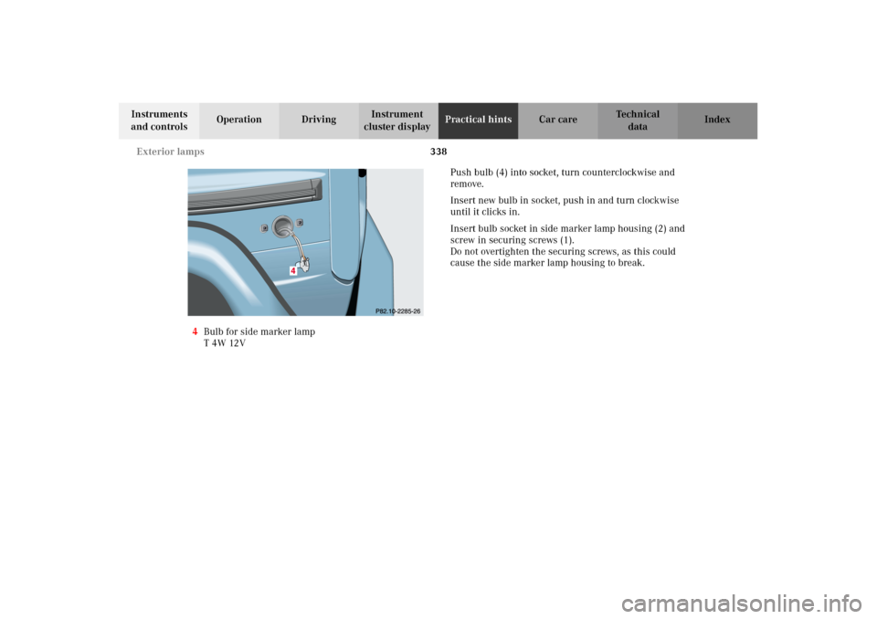
4Bulb for side marker lamp
T 4W 12V Push bulb (4) into socket, turn counterclockwise and
remove.
Insert new bulb in socket, push in and turn clockwise
until it clicks in.
Insert bulb socket in side marker lamp housing (2) and
screw in securing screws (1).
Do not overtighten the securing screws, as this could
cause the side marker lamp housing to break.
J_G463.book Seite 338 Mittwoch, 19. September 2001 8:06 08
Page 342 of 385
339 Exterior lamps
Te ch n i c a l
data Instruments
and controlsOperation DrivingInstrument
cluster displayPractical hintsCar care Index Taillamp assemblies
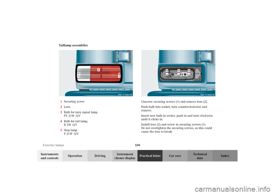
1Securing screw
2Lens
3Bulb for turn signal lamp
PY 21W 12V
4Bulb for tail lamp,
R5W12V
5Stop lamp
P21W12VUnscrew securing screws (1) and remove lens (2).
Push bulb into socket, turn counterclockwise and
remove.
Insert new bulb in socket, push in and turn clockwise
until it clicks in.
Install lens (2) and screw in securing screws (1).
Do not overtighten the securing screws, as this could
cause the lens to break.
J_G463.book Seite 339 Mittwoch, 19. September 2001 8:06 08
Page 344 of 385
341 Exterior lamps
Te ch n i c a l
data Instruments
and controlsOperation DrivingInstrument
cluster displayPractical hintsCar care Index Rear fog lamp / Backup lamp
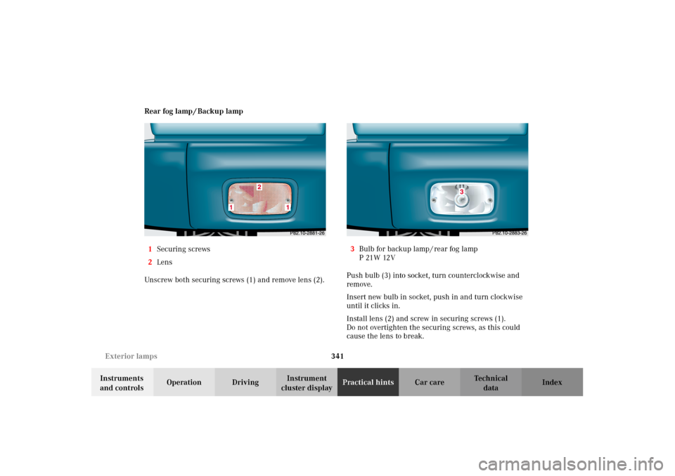
1Securing screws
2Lens
Unscrew both securing screws (1) and remove lens (2).3Bulb for backup lamp / rear fog lamp
P21W12V
Push bulb (3) into socket, turn counterclockwise and
remove.
Insert new bulb in socket, push in and turn clockwise
until it clicks in.
Install lens (2) and screw in securing screws (1).
Do not overtighten the securing screws, as this could
cause the lens to break.
J_G463.book Seite 341 Mittwoch, 19. September 2001 8:06 08
Page 349 of 385
346 Emergency operation of sliding/pop-up roof
Te ch n i c a l
data Instruments
and controlsOperation DrivingInstrument
cluster displayPractical hintsCar care Index
Emergency operation of sliding/pop-up roof
The sliding / pop-up roof can be opened or closed
manually should an electrical malfunction occur.
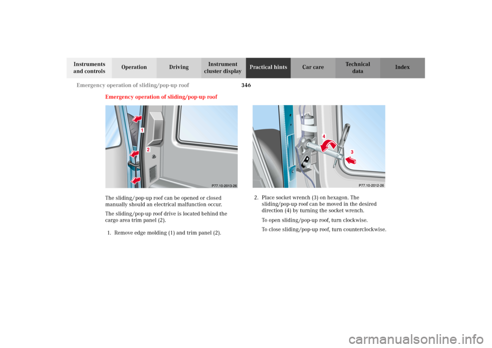
The sliding /pop-up roof drive is located behind the
cargo area trim panel (2).
1. Remove edge molding (1) and trim panel (2).2. Place socket wrench (3) on hexagon. The
sliding/pop-up roof can be moved in the desired
direction (4) by turning the socket wrench.
To open sliding /pop-up roof, turn clockwise.
To close sliding /pop-up roof, turn counterclockwise.
J_G463.book Seite 346 Mittwoch, 19. September 2001 8:06 08