2002 MERCEDES-BENZ G500 turn signal
[x] Cancel search: turn signalPage 8 of 385

5 Contents
Practical hintsFirst aid kit, vehicle tools
and jack ......................................296
CD-changer .....................................296
Fuses ................................................297
Electrical outlet .............................. 301
Stowing items in the vehicle ........ 301
Hood .................................................302
Checking engine oil level .............304
Automatic transmission
fluid level ...................................305
Engine oil consumption ................305
Coolant level ...................................306
Adding coolant ...........................306
Windshield washer/headlamp
cleaning system .........................307
Windshield and headlamp
washer fluid mixing ratio .........307Vehicle jack .................................... 308
Wheels ............................................. 310
Tire replacement ........................ 310
Rotating wheels .......................... 311
Spare wheel cover ..........................312
Spare wheel ..................................... 313
Changing wheels ............................ 314
Tire inflation pressure .................. 318
Battery .............................................. 319
Jump starting ................................. 321
Towing the vehicle ........................ 324
Transmission selector lever,
manually unlocking .................. 327
Stranded vehicle ............................ 327
Exterior lamps ............................... 328
Headlamp assembly .................. 329
Fog lamp, front ........................... 332
Turn signal lamp, front ............ 334Turn signal lamp, side ...............335
Front and rear
side marker lamps .....................337
Taillamp assemblies ..................339
License plate lamp .....................340
Rear fog lamp / Backup lamp ... 341
Changing batteries in
the electronic key .....................343
Synchronizing
remote control ............................345
Emergency operation of
sliding/pop-up roof ...................346
Manual release for
fuel filler flap .............................347
Replacing wiper blades .................348
J_G463.book Seite 5 Mittwoch, 19. September 2001 8:06 08
Page 9 of 385

6 Contents
Vehicle careCleaning and care
of the vehicle .............................350
Power washer .............................. 351
Tar stains ..................................... 351
Paintwork, painted body
components ................................. 351
Engine cleaning ..........................352
Vehicle washing .........................352
Ornamental moldings ................352
Headlamps, taillamps,
turn signal lenses ......................352
Window cleaning ........................353
Wiper blades ...............................353
Light alloy wheels ......................353
Instrument cluster .....................353
Steering wheel and
gear selector lever ......................353
Cup holder ...................................354
Seat belts .....................................354Headliner .................................... 354
Upholstery .................................. 354
Hard plastic trim items ............. 354
Plastic and rubber parts ........... 354
Technical dataSpare parts service ....................... 356
Warranty coverage ........................ 356
Identification labels ...................... 357
Layout of poly-V-belt drive ........... 358
Technical data ................................ 359
Fuels, coolants, lubricants etc. –
capacities ................................... 361
Engine oils ...................................... 363
Engine oil additives ...................... 363
Air conditioner refrigerant .......... 363
Brake fluid ...................................... 363
Premium unleaded gasoline ........ 364
Fuel requirements ........................ 364
Gasoline additives ......................... 365
Coolants .......................................... 365
Consumer information ................. 367
IndexIndex ................................................369
J_G463.book Seite 6 Mittwoch, 19. September 2001 8:06 08
Page 34 of 385
31 Central locking system
Te ch n i c a l
data Instruments
and controlsOperationDrivingInstrument
cluster displayPractical hints Car care Index Locking and unlocking with remote control
Unlocking:
Press transmit button Œ. All turn signal lamps blink
once to indicate that the vehicle is unlocked.
The remote control can be programmed for two kinds of
unlocking modes (see below):
Selective unlocking mode –
Press transmit button Œ once to unlock driver’s door
and fuel filler flap.
Press transmit button Πtwice to unlock all doors,
fuel filler flap, and tailgate.
Global unlocking mode –
Press transmit button Πonce to unlock all doors,
fuel filler flap, and tailgate.
Notes:
If the tailgate was previously locked separately, it will
remain locked, see page 39.
The presently active unlocking mode (selective or
global) can only be determined by unlocking the vehicle
with the remote control (see below for changing mode).If within 40 seconds of unlocking with the remote
control, neither door or tailgate is opened, the electronic
key is not inserted in the starter switch, or the central
locking switch is not activated, the vehicle will
automatically lock.
Locking:
Press transmit button ‹ once. All turn signal lamps
blink three times to indicate that the vehicle is locked. If
they do not blink three times, a door or the tailgate is
not properly closed.
Note:
If the vehicle cannot be locked or unlocked by pressing
the transmit button, then it may be necessary to change
the batteries in the electronic key (if ok, battery check
lamp in electronic key will light briefly when pressing
transmit button) or to synchronize the remote control,
see pages 343 and 345.
Choosing global or selective mode on remote control
Press and hold transmit buttons‹ andŒ
simultaneously for 6 seconds to reprogram the remote
control. Battery check lamp will blink two times
indicating the completed mode change.
J_G463.book Seite 31 Mittwoch, 19. September 2001 8:06 08
Page 88 of 385
85 Instrument cluster
Te ch n i c a l
data Instruments
and controlsOperationDrivingInstrument
cluster displayPractical hints Car care Index 1Knob for instrument cluster illumination,
seepage84
Reset knob for trip odometer, see page 88 and
individual settings, see page 108
2Tachometer
3Speedometer
4Left turn signal indicator lamp, see combination
switch on page 134
5Electronic stability program (ESP) warning lamp,
see page 270
6Right turn signal indicator lamp, see combination
switch on page 1347Multifunction display, see page 90
Malfunction and warning messages in the
multifunction display, see page 272
8Trip odometer, see page 88 and 94
9Main odometer, see page 94
10Display for transfer case program mode and gear
range indicators, page 210
11Malfunction/warning message memory,
seepage106
12Outside temperature indicator, see page 89
13Digital clock
To set the time, see individual settings on page 110
14Fuel gauge with reserve warning lamp, see page 268
J_G463.book Seite 85 Mittwoch, 19. September 2001 8:06 08
Page 128 of 385
125 Flexible service system
Te ch n i c a l
data Instruments
and controlsOperationDrivingInstrument
cluster displayPractical hints Car care Index The next service due date is displayed either in days or
in miles, depending on your driving style.
Once the suggested service term has passed, the symbol
and message appear for approximately 30 seconds and
a signal sounds every time when turning the electronic
key in starter switch to position 2.
The service indicator disappears automatically after
30 seconds or if the knob for instrument cluster
illumination, see page 84, in the instrument cluster is
pressed.
Calling up service indicator manually:
Turn the electronic key in starter switch to position 1
or 2.
Call up the trip odometer and main odometer by
pressing button è or ÿ on the multifunction
steering wheel until the display appears. See page 94.
Press button j or k until the FSS indicator
appears.
The next or previous system is displayed by pressing
button è or ÿ.Important!
The FSS indicator is not an engine oil level indicator.
See page 127 for engine oil level indicator.
Note:
When disconnecting vehicle battery for one or more
days at a time, such days will not be counted. Any such
days not counted by the FSS can be added by your
Mercedes-Benz Light Truck Center.
The interval between services is determined by the type
of driving for which the vehicle is used. For example,
driving at extreme speeds, and cold starts combined
wit h short distan ce d r iving in which the e ngin e d oes not
reach operating normal temperature, reduce the interval
between services.
J_G463.book Seite 125 Mittwoch, 19. September 2001 8:06 08
Page 129 of 385
126 Flexible service system
Te ch n i c a l
data Instruments
and controlsOperationDrivingInstrument
cluster displayPractical hints Car care Index
Followin g a c omp leted A or B s er vic e t he Me rced es -B en z
Center sets the counter mileage to 10 000 miles
(Canada: 15 000 km).
The counter can also be set by any individual. To do so:
Turn the electronic key in starter switch to position 1
or 2.
To call up the trip odometer and main odometer, press
button è or ÿ on the multifunction steering
wheel until the display appears. See page 94.
Press button j or k until the FSS indicator
appears.
Press the reset knob on the instrument cluster, see
page 84, for approximately 4 seconds.The multifunction display will show the question:
“DO YOU WANT TO RESET SERVICE INTERVAL? –
CONFIRM BY PRESSING R”
Press the reset knob on the instrument cluster again for
approximately 4 seconds to reset the service indicator
until a signal sounds.
The new service indicator is displayed with the reset
distance of 10 000 miles (Canada 15 000 km).
If the FSS counter was inadvertently reset, have a
Mercedes-Benz Center correct it.
However you choose to set your reference numbers, the
scheduled services as posted in the Service Booklet
must be followed to properly care for your vehicle.
J_G463.book Seite 126 Mittwoch, 19. September 2001 8:06 08
Page 137 of 385
134 Combination switch
Te ch n i c a l
data Instruments
and controlsOperationDrivingInstrument
cluster displayPractical hints Car care Index
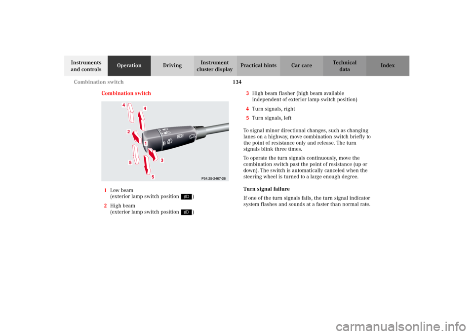
Combination switch
1Low beam
(exterior lamp switch position B)
2High beam
(exterior lamp switch position B)3High beam flasher (high beam available
independent of exterior lamp switch position)
4Turn signals, right
5Turn signals, left
To signal minor directional changes, such as changing
lanes on a highway, move combination switch briefly to
the point of resistance only and release. The turn
signals blink three times.
To operate the turn signals continuously, move the
combination switch past the point of resistance (up or
down). The switch is automatically canceled when the
steering wheel is turned to a large enough degree.
Turn signal failure
If one of the turn signals fails, the turn signal indicator
system flashes and sounds at a faster than normal rate.
J_G463.book Seite 134 Mittwoch, 19. September 2001 8:06 08
Page 142 of 385
139 Hazard warning flasher
Te ch n i c a l
data Instruments
and controlsOperationDrivingInstrument
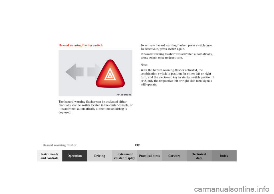
cluster displayPractical hints Car care Index Hazard warning flasher switch
The hazard warning flasher can be activated either
manually via the switch located in the center console, or
it is activated automatically at the time an airbag is
deployed.To activate hazard warning flasher, press switch once.
To deactivate, press switch again.
If hazard warning flasher was activated automatically,
press switch once to deactivate.
Note:
With the hazard warning flasher activated, the
combination switch in position for either left or right
turn, and the electronic key in starter switch position 1
or 2, only the respective left or right side turn signals
will operate.
J_G463.book Seite 139 Mittwoch, 19. September 2001 8:06 08