2002 MERCEDES-BENZ G500 turn signal
[x] Cancel search: turn signalPage 189 of 385
186 Garage door opener
Te ch n i c a l
data Instruments
and controlsOperationDrivingInstrument
cluster displayPractical hints Car care Index
For operation in the USA only: This device complies
with Part 15 of the FCC Rules. Operation is subject to
the following two conditions:
(1) This device may not cause harmful interference, and
(2) this device must accept any interference received,
including interference that may cause undesired
operation.
Any unauthorized modification to this device could void
the user’s authority to operate the equipment.
Programming or reprogramming the integrated
remote control:
1. Turn electronic key in starter switch to position 1
or 2.
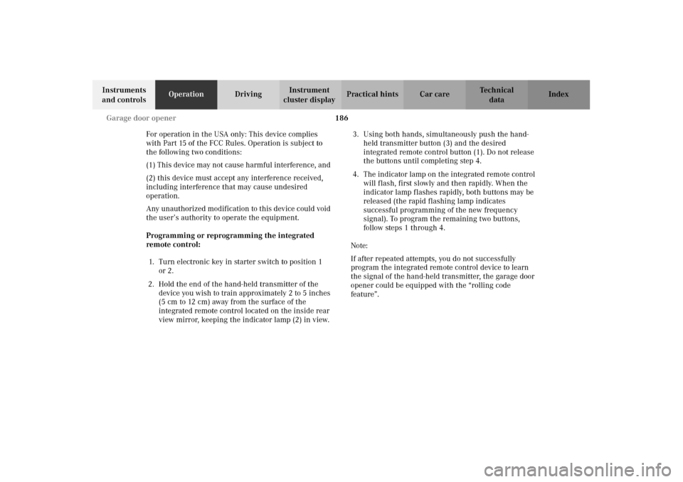
2. Hold the end of the hand-held transmitter of the
device you wish to train approximately 2 to 5 inches
(5 cm to 12 cm) away from the surface of the
integrated remote control located on the inside rear
view mirror, keeping the indicator lamp (2) in view.3. Using both hands, simultaneously push the hand-
held transmitter button (3) and the desired
integrated remote control button (1). Do not release
the buttons until completing step 4.
4. The indicator lamp on the integrated remote control
will flash, first slowly and then rapidly. When the
indicator lamp flashes rapidly, both buttons may be
released (the rapid flashing lamp indicates
successful programming of the new frequency
signal). To program the remaining two buttons,
follow steps 1 through 4.
Note:
If after repeated attempts, you do not successfully
program the integrated remote control device to learn
the signal of the hand-held transmitter, the garage door
opener could be equipped with the “rolling code
feature”.
J_G463.book Seite 186 Mittwoch, 19. September 2001 8:06 08
Page 191 of 385
188 Garage door opener
Te ch n i c a l
data Instruments
and controlsOperationDrivingInstrument
cluster displayPractical hints Car care Index
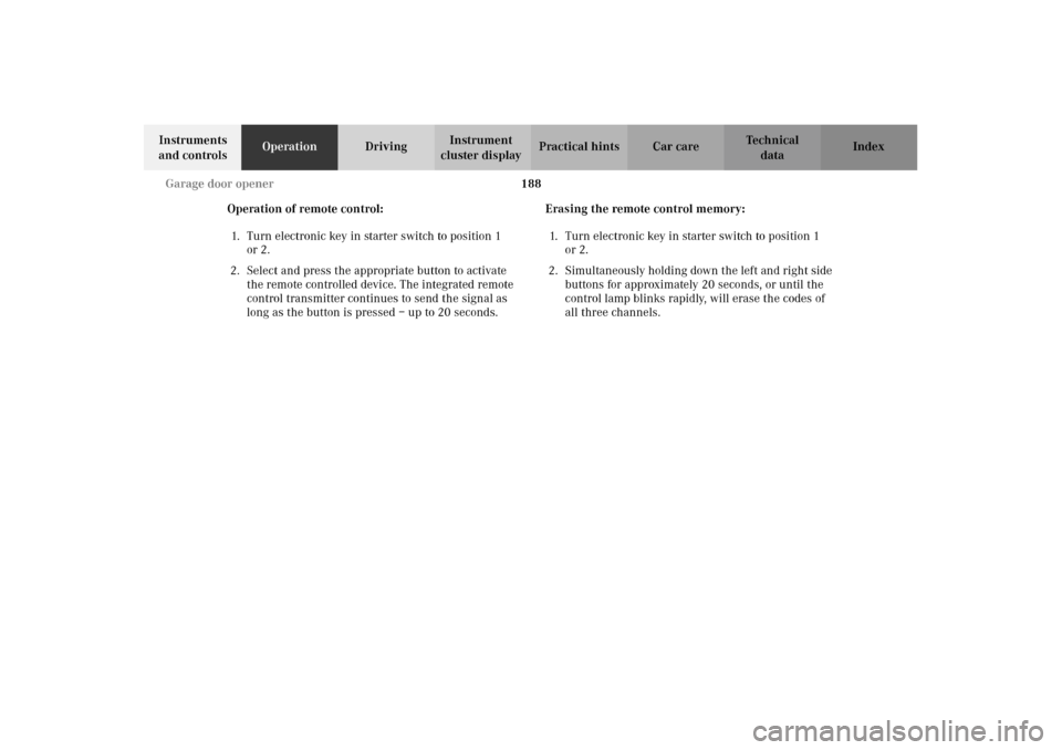
Operation of remote control:
1. Turn electronic key in starter switch to position 1
or 2.
2. Select and press the appropriate button to activate
the remote controlled device. The integrated remote
control transmitter continues to send the signal as
long as the button is pressed – up to 20 seconds.Erasing the remote control memory:
1. Turn electronic key in starter switch to position 1
or 2.
2. Simultaneously holding down the left and right side
buttons for approximately 20 seconds, or until the
control lamp blinks rapidly, will erase the codes of
all three channels.
J_G463.book Seite 188 Mittwoch, 19. September 2001 8:06 08
Page 200 of 385
197 Tele Aid
Te ch n i c a l
data Instruments
and controlsOperationDrivingInstrument
cluster displayPractical hints Car care Index Notes:
The indicator lamp in the Roadside Assistance
button remains illuminated in red for approx.
10 seconds during the system self-check after turning
electronic key in starter switch to position 2 (together
with the “SOS” button and the Information
button¡).
See system self-check on page 192 when the indicator
lamp does not light up in red or stays on longer than
approximately 10 seconds.
If the indicator lamp in the Roadside Assistance
button is illuminated continuously and there was
no voice connection to the Response Center established,
then the Tele Aid system could not initiate an Roadside
Assistance call (e.g. the relevant cellular phone network
is not available). The message “ROADSIDE
ASSISTANCE – CALL FAILED” appears in the
multifunction display.
Roadside Assistance calls can be terminated using the
ìbutton on the multifunction steering wheel.Information button ¡
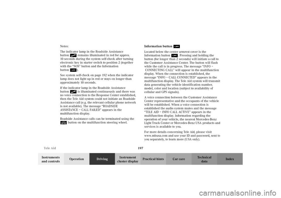
Located below the center armrest cover is the
Information button¡. Pressing and holding the
button (for longer than 2 seconds) will initiate a call to
the Customer Assistance Center. The button will flash
while the call is in progress. The message “INFO –
CONNECTING CALL” will appear in the multifunction
display. When the connection is established, the
message “INFO – CALL CONNECTED” appears in the
multifunction display. The Tele Aid system will transmit
data generating the vehicle identification number,
model, color and location (subject to availability of
cellular and GPS signals).
A voice connection between the Customer Assistance
Center representative and the occupants of the vehicle
will be established. When a voice connection is
established the audio system mutes and the message
“TELE AID – INFO CALL ACTIVE” appears in the
multifunction display. Information regarding the
operation of your vehicle, the nearest Mercedes-Benz
Light Truck Center or Mercedes-Benz USA products and
services is available to you.
For more details concerning Tele Aid, please visit
www.mbusa.com and use your ID and password, sent to
you separately, to learn more (USA only).
J_G463.book Seite 197 Mittwoch, 19. September 2001 8:06 08
Page 201 of 385
198 Tele Aid
Te ch n i c a l
data Instruments
and controlsOperationDrivingInstrument
cluster displayPractical hints Car care Index
Notes:
The indicator lamp in the Information button¡
remains illuminated in red for approx. 10 seconds
during the system self-check after turning electronic
key in starter switch to position 2 (together with the
“SOS” button and the Roadside Assistance button).
See system self-check on page 192 when the indicator
lamp does not light up in red or stays on longer than
approximately 10 seconds.
If the indicator lamp in the Information button¡ is
illuminated continuously and there was no voice
connection to the Response Center established, then the
Tele Aid system could not initiate an Information call
(e.g. the relevant cellular phone network is not
available). The message “info – CALL FAILED” appears
in the multifunction display.
Information calls can be terminated using the
ìbutton on the multifunction steering wheel.Important!
If the indicator lamps do not start flashing after
pressing one of the buttons or remain illuminated (in
red) at any time, the Tele Aid system has detected a fault
or the service is not currently active, and may not
initiate a call. Visit your Mercedes-Benz Light Truck
Center and have the system checked or contact the
Response Center at 1-800-756-9018 (in the USA) or
1-888-923-8367 (in Canada) as soon as possible.
Upgrade Signals
Tele Aid system processes calls using the following
priority.
•Automatic emergency – First priority
•Manual emergency – Second priority
•Roadside assistance – Third priority
•Information – Fourth priority
Should a higher priority call be initiated while you are
connected, an upgrade (alternating) tone will be heard,
and the appropriate indicator lamp will flash. If certain
information such as vehicle identification number or
customer information is not available, the operator may
need to retransmit.
J_G463.book Seite 198 Mittwoch, 19. September 2001 8:06 08
Page 263 of 385
260 What you should know at the gas station
Te ch n i c a l
data Instruments
and controlsOperationDrivingInstrument
cluster displayPractical hints Car care Index
•Bulbs
Front:
high and low beam: H4 60 / 55W 12V
fog lamp: H3 55W 12V
standing and parking lamp: T 4W 12V
turn signal lamp: PY 21W 12V (1156NA[cp 32])
Side:
side marker lamp yellow: T 4W 12V
side marker lamp red: T 4W 12V
turn signal lamp: WY 5W 12V 5W
Rear:
tail lamp: R 5W 12V
stop lamp: P 21W 12V
turn signal lamp: PY 21W 12V
backup lamp: P 21W 12V
fog lamp: P 21W 12V
license plate lamp: C 5W 12V (tubular)
J_G463.book Seite 260 Mittwoch, 19. September 2001 8:06 08
Page 286 of 385
283 Malfunction and warning messages
Te ch n i c a l
data Instruments
and controlsOperation DrivingInstrument
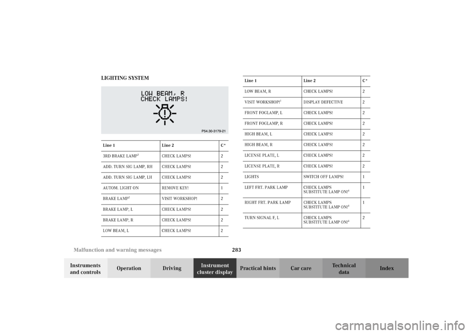
cluster displayPractical hints Car care Index LIGHTING SYSTEM
Line 1 Line 2 C*
3RD BRAKE LAMP
3
CHECK LAMPS! 2
ADD. TURN SIG LAMP, RH CHECK LAMPS! 2
ADD. TURN SIG LAMP, LH CHECK LAMPS! 2
AUTOM. LIGHT ON REMOVE KEY! 1
BRAKE LAMP
2
VISIT WORKSHOP! 2
BRAKE LAMP, L CHECK LAMPS! 2
BRAKE LAMP, R CHECK LAMPS! 2
LOW BEAM, L CHECK LAMPS! 2
LOW BEAM, R CHECK LAMPS! 2
VISIT WORKSHOP!
1
DISPLAY DEFECTIVE 2
FRONT FOGLAMP, L CHECK LAMPS! 2
FRONT FOGLAMP, R CHECK LAMPS! 2
HIGH BEAM, L CHECK LAMPS! 2
HIGH BEAM, R CHECK LAMPS! 2
LICENSE PLATE, L CHECK LAMPS! 2
LICENSE PLATE, R CHECK LAMPS! 2
LIGHTS SWITCH OFF LAMPS! 1
LEFT FRT. PARK LAMP CHECK LAMPS
SUBSTITUTE LAMP ON!
4
1
RIGHT FRT. PARK LAMP CHECK LAMPS
SUBSTITUTE LAMP ON!
4
1
TURN SIGNAL F, L CHECK LAMPS
SUBSTITUTE LAMP ON!
4
2 Line 1 Line 2 C*
J_G463.book Seite 283 Mittwoch, 19. September 2001 8:06 08
Page 287 of 385
284 Malfunction and warning messages
Te ch n i c a l
data Instruments
and controlsOperation DrivingInstrument
cluster displayPractical hints Car care Index
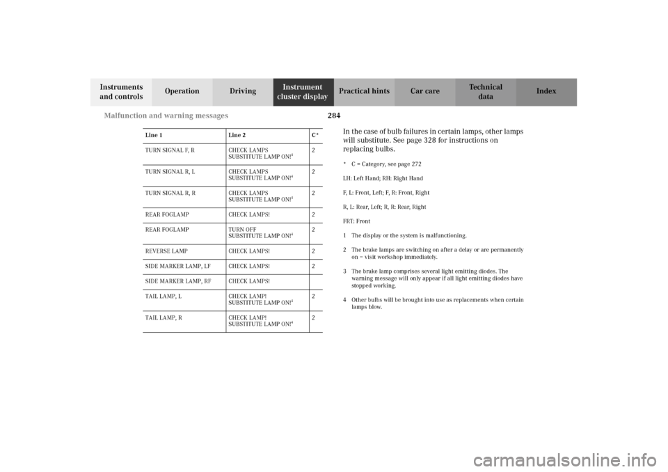
In t he c as e of bulb failur es in ce rtain lamp s, ot her lamps
will substitute. See page 328 for instructions on
replacing bulbs.
* C = Category, see page 272
LH: Left Hand; RH: Right Hand
F, L: Front, Left; F, R: Front, Right
R, L: Rear, Left; R, R: Rear, Right
FRT: Front
1 The display or the system is malfunctioning.
2 The brake lamps are switching on after a delay or are permanently
on – visit workshop immediately.
3 The brake lamp comprises several light emitting diodes. The
warning message will only appear if all light emitting diodes have
stopped working.
4 Other bulbs will be brought into use as replacements when certain
lamps blow. TURN SIGNAL F, R CHECK LAMPS
SUBSTITUTE LAMP ON!
4
2
TURN SIGNAL R, L CHECK LAMPS
SUBSTITUTE LAMP ON!
4
2
TURN SIGNAL R, R CHECK LAMPS
SUBSTITUTE LAMP ON!
4
2
REAR FOGLAMP CHECK LAMPS! 2
REAR FOGLAMP TURN OFF
SUBSTITUTE LAMP ON!
4
2
REVERSE LAMP CHECK LAMPS! 2
SIDE MARKER LAMP, LF CHECK LAMPS! 2
SIDE MARKER LAMP, RF CHECK LAMPS!
TAIL LAMP, L CHECK LAMP!
SUBSTITUTE LAMP ON!
4
2
TAIL LAMP, R CHECK LAMP!
SUBSTITUTE LAMP ON!
4
2 Line 1 Line 2 C*
J_G463.book Seite 284 Mittwoch, 19. September 2001 8:06 08
Page 298 of 385
295 Contents - Practical hints
Te ch n i c a l
data Instruments
and controlsOperation DrivingInstrument
cluster displayPractical hintsCar care Index
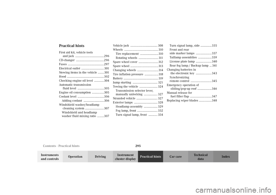
Practical hintsFirst aid kit, vehicle tools
and jack ......................................296
CD-changer .....................................296
Fuses ................................................297
Electrical outlet .............................. 301
Stowing items in the vehicle ........ 301
Hood .................................................302
Checking engine oil level .............304
Automatic transmission
fluid level ...................................305
Engine oil consumption ................305
Coolant level ...................................306
Adding coolant ...........................306
Windshield washer/headlamp
cleaning system .........................307
Windshield and headlamp
washer fluid mixing ratio .........307Vehicle jack .................................... 308
Wheels ............................................. 310
Tire replacement ........................ 310
Rotating wheels .......................... 311
Spare wheel cover ..........................312
Spare wheel ..................................... 313
Changing wheels ............................ 314
Tire inflation pressure .................. 318
Battery .............................................. 319
Jump starting ................................. 321
Towing the vehicle ........................ 324
Transmission selector lever,
manually unlocking .................. 327
Stranded vehicle ............................ 327
Exterior lamps ............................... 328
Headlamp assembly .................. 329
Fog lamp, front ........................... 332
Turn signal lamp, front ............ 334Turn signal lamp, side ...............335
Front and rear
side marker lamps .....................337
Taillamp assemblies ..................339
License plate lamp .....................340
Rear fog lamp / Backup lamp ... 341
Changing batteries in
the electronic key .....................343
Synchronizing
remote control ............................345
Emergency operation of
sliding/pop-up roof ...................346
Manual release for
fuel filler flap .............................347
Replacing wiper blades .................348
J_G463.book Seite 295 Mittwoch, 19. September 2001 8:06 08