2002 MERCEDES-BENZ G500 towing
[x] Cancel search: towingPage 8 of 385

5 Contents
Practical hintsFirst aid kit, vehicle tools
and jack ......................................296
CD-changer .....................................296
Fuses ................................................297
Electrical outlet .............................. 301
Stowing items in the vehicle ........ 301
Hood .................................................302
Checking engine oil level .............304
Automatic transmission
fluid level ...................................305
Engine oil consumption ................305
Coolant level ...................................306
Adding coolant ...........................306
Windshield washer/headlamp
cleaning system .........................307
Windshield and headlamp
washer fluid mixing ratio .........307Vehicle jack .................................... 308
Wheels ............................................. 310
Tire replacement ........................ 310
Rotating wheels .......................... 311
Spare wheel cover ..........................312
Spare wheel ..................................... 313
Changing wheels ............................ 314
Tire inflation pressure .................. 318
Battery .............................................. 319
Jump starting ................................. 321
Towing the vehicle ........................ 324
Transmission selector lever,
manually unlocking .................. 327
Stranded vehicle ............................ 327
Exterior lamps ............................... 328
Headlamp assembly .................. 329
Fog lamp, front ........................... 332
Turn signal lamp, front ............ 334Turn signal lamp, side ...............335
Front and rear
side marker lamps .....................337
Taillamp assemblies ..................339
License plate lamp .....................340
Rear fog lamp / Backup lamp ... 341
Changing batteries in
the electronic key .....................343
Synchronizing
remote control ............................345
Emergency operation of
sliding/pop-up roof ...................346
Manual release for
fuel filler flap .............................347
Replacing wiper blades .................348
J_G463.book Seite 5 Mittwoch, 19. September 2001 8:06 08
Page 44 of 385
41 Central locking system
Te ch n i c a l
data Instruments
and controlsOperationDrivingInstrument
cluster displayPractical hints Car care Index Automatic central locking
Wit h t he autom atic c entral lockin g s ystem ac tivate d, t he
doors and tailgate are locked at vehicle speeds of
approximately 9 mph (15 km / h) or more. The fuel filler
flap remains unlocked.
The automatic central locking function can be switched
on or off in the individual setting menu “VEHICLE” –
“AUTOMATIC DOOR LOCK”, see page 118.
Notes:
If doors are unlocked with the central locking switch
after activating the automatic central locking, and
neither door is opened, then the doors remain unlocked
even at vehicle speeds of approximately 9 mph
(15 km / h) or more.
If a door is opened from the inside at speeds of
approximately 9 mph (15 km / h) or less with the
automatic central locking activated, the door will again
be automatically locked at speeds of approximately
9 mph (15 km / h) or more.Important!
When towing the vehicle, or with the vehicle on a
dynamometer test stand, please, note the following:
With the automatic central locking activated and the
electronic key in starter switch position 2, the vehicle
doors will lock if the left front wheel spin at vehicle
speeds of approximately 9 mph (15 km / h) or more.
Emergency unlocking in case of accident
The doors unlock automatically a short time after an
accident in which an airbag or emergency tensioning
retractor deploys (this is intended to aid rescue and
exit).
J_G463.book Seite 41 Mittwoch, 19. September 2001 8:06 08
Page 46 of 385
43 Tow-away alarm
Te ch n i c a l
data Instruments
and controlsOperationDrivingInstrument
cluster displayPractical hints Car care Index Tow - away a l a r m
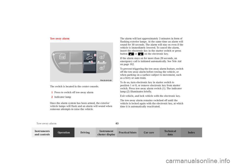
The switch is located in the center console.
1Press to switch off tow-away alarm
2Indicator lamp
Once the alarm system has been armed, the exterior
vehicle lamps will flash and an alarm will sound when
someone attempts to raise the vehicle.The alarm will last approximately 3 minutes in form of
flashing exterior lamps. At the same time an alarm will
sound for 30 seconds. The alarm will stay on even if the
vehicle is immediately lowered. To cancel the alarm,
insert the electronic key in the starter switch or press
buttonŒ or‹ on the electronic key.
If the alarm stays on for more than 20 seconds, an
emergency call is initiated automatically. See Tele Aid
on page 192.
To pr even t tr igger in g t he tow-away alarm feature, switch
off the tow-away alarm before towing the vehicle, or
when parking on a surface subject to movement, such
as a ferry or auto train.
To do so, turn electronic key in starter switch to
position 1 or 0, or remove electronic key from starter
switch. Press tow-away alarm switch (1). The indicator
lamp (2) illuminates briefly.
Exit vehicle, and lock vehicle with the electronic key.
The tow-away alarm remains switched off until the
vehicle is locked again with the electronic key, at which
time it is automatically reactivated.
J_G463.book Seite 43 Mittwoch, 19. September 2001 8:06 08
Page 165 of 385
162 Interior equipment
Te ch n i c a l
data Instruments
and controlsOperationDrivingInstrument
cluster displayPractical hints Car care Index
Interior Storage compartments, armrest and cup holder
Wa r n i n g !
To help avoid personal injury during a collision or
sudden maneuver, exercise care when stowing
things. Put luggage or cargo in the rear cargo area
and secure. Do not pile luggage or cargo higher
than the seat backs. Luggage nets cannot secure hard or heavy objects.Wa r n i n g !
Do not load items on the roof. It may cause
instability during some maneuvers which could
result in an accident.
Wa r n i n g !
Keep compartment lids closed. This will help to
prevent stored objects from being thrown about
and injuring vehicle occupants during an accident
and sudden maneuvers.
J_G463.book Seite 162 Mittwoch, 19. September 2001 8:06 08
Page 199 of 385
196 Tele Aid
Te ch n i c a l
data Instruments
and controlsOperationDrivingInstrument
cluster displayPractical hints Car care Index
Roadside Assistance button
Located below the center armrest cover is the Roadside
Assistance button. Pressing and holding the
button (for longer than 2 seconds) will initiate a call to a
Mercedes-Benz Roadside Assistance dispatcher. The
button will flash while the call is in progress. The
message “ROADSIDE ASSISTANCE – CONNECTING
CALL” will appear in the multifunction display. When
the connection is established, the message “ROADSIDE
ASSISTANCE – CALL CONNECTED” appears in the
multifunction display. The Tele Aid system will transmit
data generating the vehicle identification number,
model, color and location (subject to availability of
cellular and GPS signals).A voice connection between the Roadside Assistance
dispatcher and the occupants of the vehicle will be
established. When a voice connection is established the
audio system mutes and the message “TELE AID -
ROADSIDE ASSISTANCE CALL ACTIVE” appears in the
multifunction display. The nature of the need for
assistance can then be described. The Mercedes-Benz
Roadside assistance dispatcher will either dispatch a
qualified Mercedes-Benz technician or arrange to tow
your vehicle to the nearest Mercedes-Benz Center. For
ser vic es s uch as labor an d / or towing charges m ay ap ply.
Refer to the Roadside Assistance manual for more
information.
These programs are only available in the USA:
•S ign an d Drive s erv ices : Ser vices such as jump start,
a few gallons of fuel or the replacement of a flat tire
with the vehicle spare tire are obtainable,
•Remote Vehicle Diagnostics: This function permits
the Mercedes-Benz Roadside Assistance dispatcher
to download malfunction codes and actual vehicle
data.
Wa r n i n g !
If you feel at any way in jeopardy when in the
vehicle (e.g. smoke or fire in the vehicle, vehicle in
a dangerous road location), please do not wait for
voice contact after you have pressed the emergency
button. Carefully leave the vehicle and move to a
safe location. The Response Center will
automatically contact local emergency officials
with the vehicle’s approximate location if they
rec eive a n a utom at ic “SO S” si gna l a nd ca nn ot ma ke
voice contact with the vehicle occupants.
J_G463.book Seite 196 Mittwoch, 19. September 2001 8:06 08
Page 222 of 385
219 Driving instructions
Te ch n i c a l
data Instruments
and controlsOperationDrivingInstrument
cluster displayPractical hints Car care Index Parking
Important!
It is advisable to set the parking brake whenever
parking or leaving the vehicle. In addition, move
selector lever to position “P”.
When parking on hills, always set the parking brake.Tires
Tread wear indicators (TWI) are required by law. These
indicators are located in six places on the tread
circumference and become visible at a tread depth of
approximately
1/16in (1.5 mm), at which point the tire is
considered worn and should be replaced.
The tread wear indicator appears as a solid band across
the tread.
Note:
For instructions on towing the vehicle, see page 324.
Wa r n i n g !
To reduce the risk of personal injury as a result of
vehicle movement, before
turning off the engine
and leaving the vehicle, always:
1. Keep right foot on the service brake pedal.
2. Pull the parking brake lever up as many
notches as possible.
3. Move the selector lever to position “P”.
4. Slowly release the service brake pedal.
5. Turn front wheels towards the road curb.
6. Turn the electronic key to starter switch
position 0 and remove.
7. Take the key and lock vehicle when leaving.
Wa r n i n g !
If you feel a sudden significant vibration or ride
disturbance, or you suspect that possible damage to
your vehicle has occurred, you should turn on the
hazard warning flashers, carefully slow down, and
drive with caution to an area which is a safe
distance from the roadway.Inspect the tires and under the vehicle for possible
damage. If the vehicle or tires appear unsafe, have
it towed to the nearest Mercedes-Benz Light Truck
Center or tire dealer for repairs.
J_G463.book Seite 219 Mittwoch, 19. September 2001 8:06 08
Page 244 of 385
241 Driving systems
Te ch n i c a l
data Instruments
and controlsOperationDrivingInstrument
cluster displayPractical hints Car care Index Four-wheel electronic traction system (4-ETS)
With the electronic key in starter switch position 2, the
warning lampv located in the speedometer dial
comes on and should go out when the engine is
running.
The 4-ETS improves vehicle’s ability to utilize available
traction, especially under slippery road conditions. The
brakes are applied to the spinning wheel and power is
transferred to the wheel(s) with traction. The 4-ETS
function is available between vehicle speed
0 mph (km / h) and 37 mph (60 km / h).
The 4-ETS warning lampv starts to flash at any
vehicle speed, as soon as the tires loose traction and the
wheels begin to spin.
Important!
If the 4-ETS warning lampv flashes:
•during take-off, apply as little throttle as possible,
•while driving, ease up on the accelerator.
Adapt your speed and driving to the prevailing road
conditions.4-ETS Control
If the É malfunction indicator lamp and the ESP
warning lamp stay illuminated and warning messages
appears in the multifunction display with the engine
running, a malfunction has been detected.
Have the 4-ETS checked at your authorized
Mercedes-Benz Light Truck Center as soon as possible.
With the ABS malfunctioning, the 4-ETS is also
switched off.
Caution!
If the vehicle is towed with the front axle raised (see
towing the vehicle on page 324), or when testing the
parking brake on a brake test dynamometer, the engine
must be shut off (electronic key in starter switch
position 0 or 1). Otherwise, the electronic traction
system will immediately be engaged and will apply the
rear wheel brakes.
J_G463.book Seite 241 Mittwoch, 19. September 2001 8:06 08
Page 246 of 385
243 Driving systems
Te ch n i c a l
data Instruments
and controlsOperationDrivingInstrument
cluster displayPractical hints Car care Index Electronic stability program (ESP)
The ESP enhances directional control and reduces
driving wheel spin of the vehicle under various driving
conditions.
Over-/understeering of the vehicle is counteracted by
applying brakes to the appropriate wheel to create a
countervailing vehicle movement. Engine torque is also
limited. The ESP warning lamp, located in the
speedometer dial, starts to flash when ESP is in
operation.Important!
If the ESP warning lampv flashes:
•During take-off apply as little throttle as possible.
•While driving ease up on the accelerator.
•Adapt your speed and driving to the prevailing road
conditions.
•Do not switch off the ESP.
Caution!
If the vehicle is towed with the front axle raised (see
towing the vehicle on page 324), the engine must be
shut off (electronic key in starter switch position 0 or 1).
Otherwise, the ESP will immediately be engaged and
will apply the rear wheel brakes.
Notes:
The yellow ESP warning lampv in the speedometer
dial comes on with the electronic key in starter switch
position 2. They should go out with the engine running.
Wa r n i n g !
ESP cannot prevent the natural laws of physics
from acting on the vehicle, nor can it increase the
traction afforded. The ESP cannot prevent
ac c id ent s, i nc l udi ng t hose resul tin g from exc es si ve
speed in turns, or aquaplaning. Only a safe,
attentive, and skillful driver can prevent accidents.
The capabilities of an ESP equipped vehicle must
never be exploited in a reckless or dangerous
manner which could jeopardize the user’s safety or
the safety of others.
J_G463.book Seite 243 Mittwoch, 19. September 2001 8:06 08