2002 MERCEDES-BENZ G500 ESP
[x] Cancel search: ESPPage 260 of 385
257 Driving systems
Te ch n i c a l
data Instruments
and controlsOperationDrivingInstrument
cluster displayPractical hints Car care Index Important!
When running on a (single-axle) dynamometer – no
matter how briefly – the non driven axle must be
raised or its drive shaft disconnected. The transfer
differential lock must be engaged. Otherwise the
transfer case can be damaged, which is not covered
by the Mercedes-Benz Limited Warranty.
Wa r n i n g !
Never drive on pavement with activated differential
locks.Steering control will be strongly affected with the
front differential lock activated.ABS, BAS and ESP are switched off automatically
when the transfer case differential lock is
activated.
J_G463.book Seite 257 Mittwoch, 19. September 2001 8:06 08
Page 266 of 385
263 Contents - Instrument cluster display
Te ch n i c a l
data Instruments
and controlsOperation DrivingInstrument
cluster displayPractical hints Car care Index
Instrument cluster displayMalfunction and indicator
lamps in the
instrument cluster ....................264
On-board diagnostic system .........265
Check engine malfunction
indicator lamp .............................265
Brake warning lamp ..................266
Supplemental restraint system
(SRS) indicator lamp ..................267
Fuel reserve warning .................268
ABS malfunction
indicator lamp .............................269
Electronic stability program
(ESP) — warning lamp ...............270
Seat belt nonusage
warning lamp .............................270
Malfunction and indicator lamp
in the center console ................ 271
AIRBAG OFF indicator lamp ..... 271Malfunction and warning
messages in the
multifunction display .............. 272
DISPLAY DEFECTIVE
(engine control unit) ................. 273
DISPLAY DEFECTIVE
(several systems) ....................... 273
BATTERY / ALTERNATOR ........274
ANTILOCK BRAKE SYSTEM .... 275
BRAKE ASSIST ............................276
BRAKE PAD WEAR .................... 277
BRAKE FLUID ............................ 277
PARKING BRAKE ....................... 278
SEAT BELT SYSTEM .................. 278
ELEC. STABIL. PROG.
(Electronic stability program) . 279
COOLANT
(coolant level) ............................. 280
COOLANT
(coolant temperature) ............... 281
ENGINE OIL LEVEL ................... 282LIGHTING SYSTEM ....................283
LIGHT SENSOR ...........................285
DOOR ...........................................285
TRUNK OPEN .............................286
HOOD ...........................................286
TELEPHONE – FUNCTION .......287
TELE AID .....................................287
WASHER FLUID .........................288
RESTRAINT SYSTEM .................289
KEY ...............................................289
FUEL RESERVE ..........................290
UNDERVOLTAGE ........................290
ELECTRONIC BRAKE BOOSTER
(EBB) ............................................ 291
ENGINE AIR FILTER .................. 291
TC SHIFT ....................................292
TC SHIFT CONDITIONS ............292
TC IN NEUTRAL .........................293
TRANSFER CASE .......................293
J_G463.book Seite 263 Mittwoch, 19. September 2001 8:06 08
Page 272 of 385
269 Malfunction and indicator lamps
Te ch n i c a l
data Instruments
and controlsOperation DrivingInstrument
cluster displayPractical hints Car care Index ABS malfunction indicator lamp
The ABS malfunction indicator lamp in the
instrument cluster comes on with the
electronic key in starter switch position 2
and should go out with the engine running.
When the ABS malfunction indicator lamp symbol and
warning in the instrument cluster remains illuminated
while the engine is running, it indicates that the ABS
has detected a malfunction and has switched off. In this
case, the brake system functions in the usual manner,
but without antilock assistance.
A malfunctioning ABS control unit can possibly affect
the operation of other systems (e.g. Navigation,
Automatic transmission). Be guided accordingly with
respect to the use of those systems and have the system
checked at your authorized Mercedes-Benz Light Truck
Center as soon as possible.
With the ABS malfunctioning the BAS, ESP, EBB and
4-ETS are also switched off. The malfunction indicator
lamps and malfunction messages in the multifunction
display come on with the engine running.If a warning tone sounds for 5 seconds and the warning
lamps- and É are displayed in the instrument
cluster, the EBB has a malfunction and is switched off.
See page 242 for notes on the electronic brake booster
(EBB).
If the charging voltage falls below 10 volts, the
malfunction indicator lamp comes on and the ABS is
switched off. When the voltage is above this value again,
the malfunction indicator lamp should go out and the
ABS is operational.
Have the system checked at your authorized
Mercedes-Benz Light Truck Center as soon as possible.
See page 239 for notes on antilock brake system (ABS).
Note:
If the transfer case differential lock is engaged the ABS
warning lamp comes on and the ABS, ESP, BAS, EBB
and 4-ETS are switched off. There is no malfunction in
the system.
ABS
J_G463.book Seite 269 Mittwoch, 19. September 2001 8:06 08
Page 273 of 385
270 Malfunction and indicator lamps
Te ch n i c a l
data Instruments
and controlsOperation DrivingInstrument
cluster displayPractical hints Car care Index
Electronic stability program (ESP) — warning lamp
The yellow ESP warning lamp in the
speedometer dial comes on with the
electronic key in starter switch position 2.
It should go out with engine running.
If the ESP malfunction indicator lamp remains
illuminated with the engine running, a malfunction has
been detected in the system. Pressing the accelerator
pedal will require greater effort. Only partial engine
output will be available.
With the ESP malfunctioning, the abs, BAS, EBB and
4-ETS are also switched off.
See electronic stability program (ESP) on page 243 if the
warning lamp lights up or flashes when the vehicle is
moving.
Note:
If the transfer case differential lock is engaged the ESP
warning lamp comes on and the ESP, ABS, BAS and
4-ETS are switched off. There is no malfunction in the
system.Seat belt nonusage warning lamp
With the electronic key in starter switch
position 2, the seat belt nonusage warning
lamp comes on, and a warning sounds for a
short time if the drivers seat belt is not fastened.
After starting the engine, the seat belt nonusage
warning lamp blinks for a brief period to remind the
driver and passengers to fasten seat belts.
J_G463.book Seite 270 Mittwoch, 19. September 2001 8:06 08
Page 282 of 385
279 Malfunction and warning messages
Te ch n i c a l
data Instruments
and controlsOperation DrivingInstrument
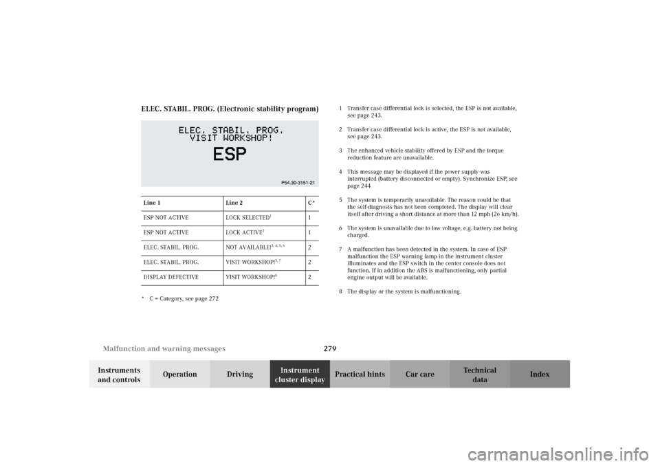
cluster displayPractical hints Car care Index ELEC. STABIL. PROG. (Electronic stability program)
* C = Category, see page 2721 Transfer case differential lock is selected, the ESP is not available,
see page 243.
2 Transfer case differential lock is active, the ESP is not available,
see page 243.
3 The enhanced vehicle stability offered by ESP and the torque
reduction feature are unavailable.
4 This message may be displayed if the power supply was
interrupted (battery disconnected or empty). Synchronize ESP, see
page 244
5 The system is temporarily unavailable. The reason could be that
the self-diagnosis has not been completed. The display will clear
itself after driving a short distance at more than 12 mph (2o km/h).
6 The system is unavailable due to low voltage, e.g. battery not being
charged.
7 A malfunction has been detected in the system. In case of ESP
malfunction the ESP warning lamp in the instrument cluster
illuminates and the ESP switch in the center console does not
function. If in addition the ABS is malfunctioning, only partial
engine output will be available.
8 The display or the system is malfunctioning. Line 1 Line 2 C*
ESP NOT ACTIVE LOCK SELECTED
1
1
ESP NOT ACTIVE LOCK ACTIVE
2
1
ELEC. STABIL. PROG. NOT AVAILABLE!
3, 4, 5, 6
2
ELEC. STABIL. PROG. VISIT WORKSHOP!
3, 7
2
DISPLAY DEFECTIVE VISIT WORKSHOP!
8
2
J_G463.book Seite 279 Mittwoch, 19. September 2001 8:06 08
Page 290 of 385
287 Malfunction and warning messages
Te ch n i c a l
data Instruments
and controlsOperation DrivingInstrument
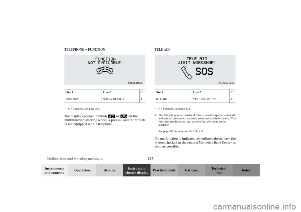
cluster displayPractical hints Car care Index TELEPHONE – FUNCTION
* C = Category, see page 272.The display appears if button í or ì on the
multifunction steering wheel is pressed and the vehicle
is not equipped with a telephone.TELE AID
* C = Category, see page 272.
1 The Tele Aid system consists of three types of response; automatic
and manual emergency, roadside assistance and information. With
this message displayed, one or more functions may not be
available.
See page 192 for notes on the Tele Aid.If a malfunction is indicated as outlined above, have the
system checked at the nearest Mercedes-Benz Center as
soon as possible.
Line 1 Line 2 C*
FUNCTION NOT AVAILABLE! 3
Line 1 Line 2 C*
TE L E A I D V I S I T WO R KS H O P !
1
1
J_G463.book Seite 287 Mittwoch, 19. September 2001 8:06 08
Page 311 of 385
308 Spare wheel, vehicle jack
Te ch n i c a l
data Instruments
and controlsOperation DrivingInstrument
cluster displayPractical hintsCar care Index
Jack
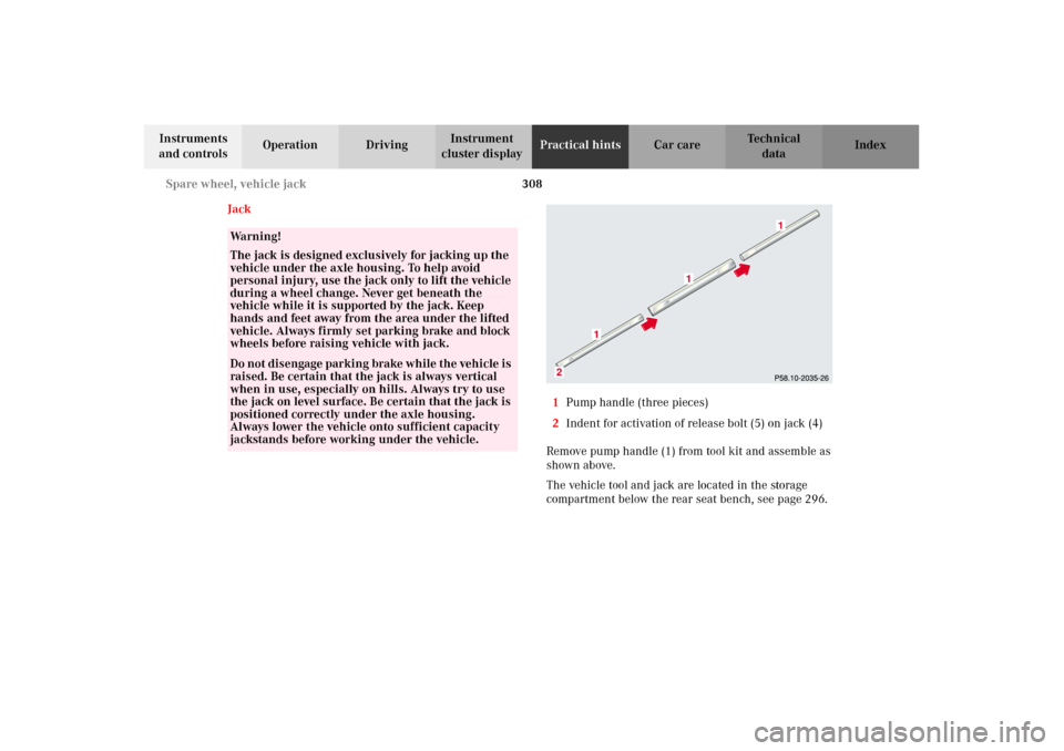
1Pump handle (three pieces)
2Indent for activation of release bolt (5) on jack (4)
Remove pump handle (1) from tool kit and assemble as
shown above.
The vehicle tool and jack are located in the storage
compartment below the rear seat bench, see page 296.
Wa r n i n g !
The jack is designed exclusively for jacking up the
vehicle under the axle housing. To help avoid
personal injury, use the jack only to lift the vehicle
during a wheel change. Never get beneath the
vehicle while it is supported by the jack. Keep
hands and feet away from the area under the lifted
vehicle. Always firmly set parking brake and block
wheels before raising vehicle with jack.Do n ot d is engage parki n g brake w hil e t he vehi c le i s
raised. Be certain that the jack is always vertical
when in use, especially on hills. Always try to use
the jack on level surface. Be certain that the jack is
positioned correctly under the axle housing.
Always lower the vehicle onto sufficient capacity
jackstands before working under the vehicle.
J_G463.book Seite 308 Mittwoch, 19. September 2001 8:06 08
Page 317 of 385
314 Tires, Wheels
Te ch n i c a l
data Instruments
and controlsOperation DrivingInstrument
cluster displayPractical hintsCar care Index
Changing wheels
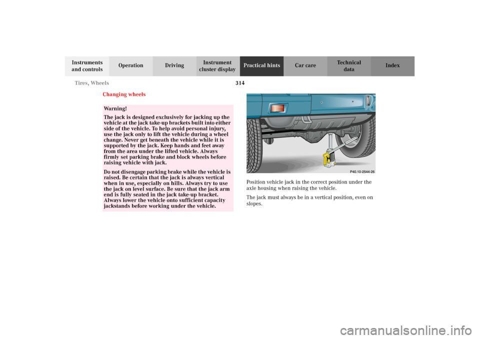
Position vehicle jack in the correct position under the
axle housing when raising the vehicle.
The jack must always be in a vertical position, even on
slopes.
Wa r n i n g !
The jack is designed exclusively for jacking up the
vehi c le a t the j ack take-up b ra ckets b ui lt i nto eit her
side of the vehicle. To help avoid personal injury,
use the jack only to lift the vehicle during a wheel
change. Never get beneath the vehicle while it is
supported by the jack. Keep hands and feet away
from the area under the lifted vehicle. Always
firmly set parking brake and block wheels before
raising vehicle with jack.Do n ot d is engage parki n g brake w hil e t he vehi c le i s
raised. Be certain that the jack is always vertical
when in use, especially on hills. Always try to use
the jack on level surface. Be sure that the jack arm
end is fully seated in the jack take-up bracket.
Always lower the vehicle onto sufficient capacity
jackstands before working under the vehicle.
J_G463.book Seite 314 Mittwoch, 19. September 2001 8:06 08