Page 1229 of 1672
SUNROOF
76-6-14 REPAIRS
Sunroof - rear
$% 76.84.02
Remove
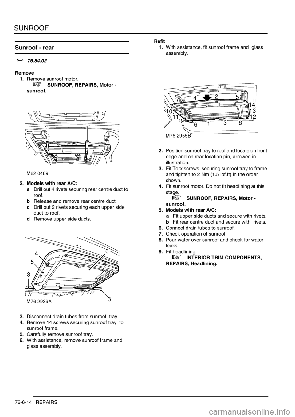
1.Remove sunroof motor.
+ SUNROOF, REPAIRS, Motor -
sunroof.
2. Models with rear A/C:
aDrill out 4 rivets securing rear centre duct to
roof.
bRelease and remove rear centre duct.
cDrill out 2 rivets securing each upper side
duct to roof.
dRemove upper side ducts.
3.Disconnect drain tubes from sunroof tray.
4.Remove 14 screws securing sunroof tray to
sunroof frame.
5.Carefully remove sunroof tray.
6.With assistance, remove sunroof frame and
glass assembly. Refit
1.With assistance, fit sunroof frame and glass
assembly.
2.Position sunroof tray to roof and locate on front
edge and on rear location pin, arrowed in
illustration.
3.Fit Torx screws securing sunroof tray to frame
and tighten to 2 Nm (1.5 lbf.ft) in the order
shown.
4.Fit sunroof motor. Do not fit headlining at this
stage.
+ SUNROOF, REPAIRS, Motor -
sunroof.
5. Models with rear A/C:
aFit upper side ducts and secure with rivets.
bFit rear centre duct and secure with rivets.
6.Connect drain tubes to sunroof.
7.Check operation of sunroof.
8.Pour water over sunroof and check for water
leaks.
9.Fit headlining.
+ INTERIOR TRIM COMPONENTS,
REPAIRS, Headlining.
Page 1230 of 1672
SUNROOF
REPAIRS 76-6-15
Glass panel - sunroof
$% 76.84.03
The procedure for replacing the rear sunroof glass
panel is exactly the same as for the front
Remove
1.Partially open sunroof.
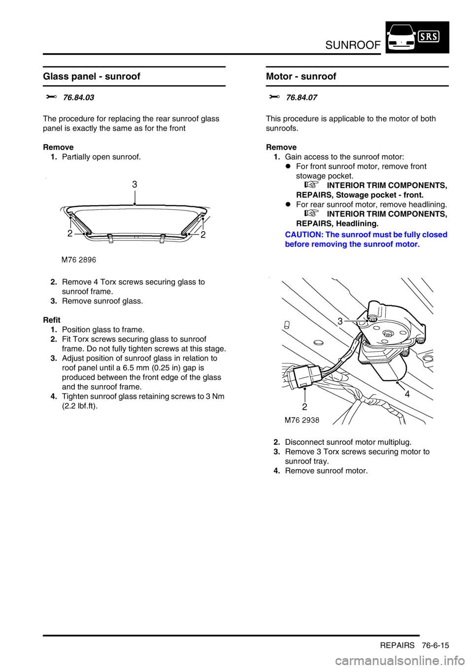
2.Remove 4 Torx screws securing glass to
sunroof frame.
3.Remove sunroof glass.
Refit
1.Position glass to frame.
2.Fit Torx screws securing glass to sunroof
frame. Do not fully tighten screws at this stage.
3.Adjust position of sunroof glass in relation to
roof panel until a 6.5 mm (0.25 in) gap is
produced between the front edge of the glass
and the sunroof frame.
4.Tighten sunroof glass retaining screws to 3 Nm
(2.2 lbf.ft).
Motor - sunroof
$% 76.84.07
This procedure is applicable to the motor of both
sunroofs.
Remove
1.Gain access to the sunroof motor:
lFor front sunroof motor, remove front
stowage pocket.
+ INTERIOR TRIM COMPONENTS,
REPAIRS, Stowage pocket - front.
lFor rear sunroof motor, remove headlining.
+ INTERIOR TRIM COMPONENTS,
REPAIRS, Headlining.
CAUTION: The sunroof must be fully closed
before removing the sunroof motor.
2.Disconnect sunroof motor multiplug.
3.Remove 3 Torx screws securing motor to
sunroof tray.
4.Remove sunroof motor.
Page 1231 of 1672
SUNROOF
76-6-16 REPAIRS
Refit
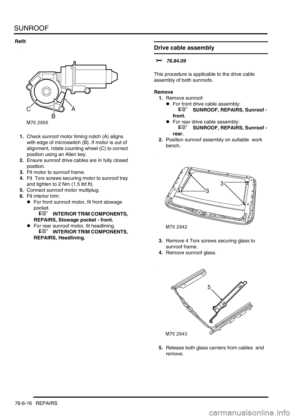
1.Check sunroof motor timing notch (A) aligns
with edge of microswitch (B). If motor is out of
alignment, rotate counting wheel (C) to correct
position using an Allen key.
2.Ensure sunroof drive cables are in fully closed
position.
3.Fit motor to sunroof frame.
4.Fit Torx screws securing motor to sunroof tray
and tighten to 2 Nm (1.5 lbf.ft).
5.Connect sunroof motor multiplug.
6.Fit interior trim:
lFor front sunroof motor, fit front stowage
pocket.
+ INTERIOR TRIM COMPONENTS,
REPAIRS, Stowage pocket - front.
lFor rear sunroof motor, fit headlining.
+ INTERIOR TRIM COMPONENTS,
REPAIRS, Headlining.
Drive cable assembly
$% 76.84.09
This procedure is applicable to the drive cable
assembly of both sunroofs.
Remove
1.Remove sunroof:
lFor front drive cable assembly:
+ SUNROOF, REPAIRS, Sunroof -
front.
lFor rear drive cable assembly:
+ SUNROOF, REPAIRS, Sunroof -
rear.
2.Position sunroof assembly on suitable work
bench.
3.Remove 4 Torx screws securing glass to
sunroof frame.
4.Remove sunroof glass.
5.Release both glass carriers from cables and
remove.
Page 1232 of 1672
SUNROOF
REPAIRS 76-6-17
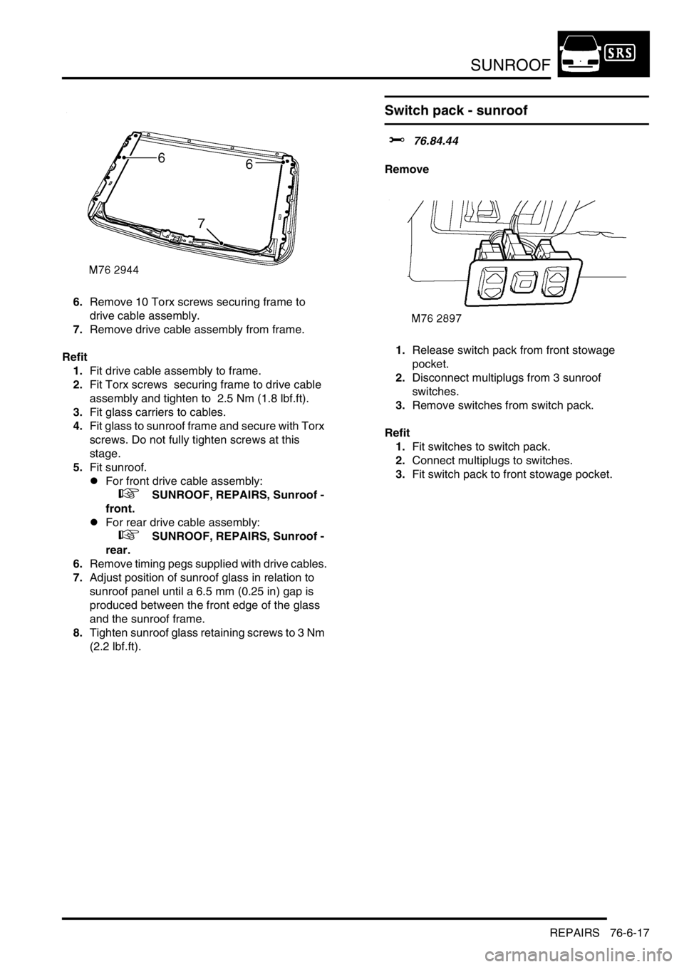
6.Remove 10 Torx screws securing frame to
drive cable assembly.
7.Remove drive cable assembly from frame.
Refit
1.Fit drive cable assembly to frame.
2.Fit Torx screws securing frame to drive cable
assembly and tighten to 2.5 Nm (1.8 lbf.ft).
3.Fit glass carriers to cables.
4.Fit glass to sunroof frame and secure with Torx
screws. Do not fully tighten screws at this
stage.
5.Fit sunroof.
lFor front drive cable assembly:
+ SUNROOF, REPAIRS, Sunroof -
front.
lFor rear drive cable assembly:
+ SUNROOF, REPAIRS, Sunroof -
rear.
6.Remove timing pegs supplied with drive cables.
7.Adjust position of sunroof glass in relation to
sunroof panel until a 6.5 mm (0.25 in) gap is
produced between the front edge of the glass
and the sunroof frame.
8.Tighten sunroof glass retaining screws to 3 Nm
(2.2 lbf.ft).
Switch pack - sunroof
$% 76.84.44
Remove
1.Release switch pack from front stowage
pocket.
2.Disconnect multiplugs from 3 sunroof
switches.
3.Remove switches from switch pack.
Refit
1.Fit switches to switch pack.
2.Connect multiplugs to switches.
3.Fit switch pack to front stowage pocket.
Page 1233 of 1672
SUNROOF
76-6-18 REPAIRS
ECU - sunroof
$% 76.84.46
Remove
1.Remove front stowage pocket.
+ INTERIOR TRIM COMPONENTS,
REPAIRS, Stowage pocket - front.
2.Remove 2 screws securing ECU to roof.
3.Disconnect 2 multiplugs from ECU.
4.Remove sunroof ECU.
Refit
1.Position sunroof ECU and connect multiplugs.
2.Fit and tighten screws securing ECU to roof.
3.Fit front stowage pocket.
+ INTERIOR TRIM COMPONENTS,
REPAIRS, Stowage pocket - front.
Page 1263 of 1672
PANEL REPAIRS
77-2-14 PROCEDURES
Electronic control units
The electronic control units (ECU) fitted to vehicles make it advisable to follow suitable precautions prior to carrying
out welding repair operations. Harsh conditions of heat and vibration may be generated during these operations which
could cause damage to the units.
In particular, it is essential to follow the appropriate precautions when disconnecting or removing the airbag DCU.
Supplementary Restraint System Precautions
Any work undertaken which involves the removal or replacement of any item of the Supplementary Restraint System
(SRS), requires extreme caution and the appropriate precautions must be followed.
+ GENERAL INFORMATION, Supplementary Restraint System Precautions.
Equipment
Prior to commencing any test procedure on the vehicle, ensure that the relevant test equipment is working correctly
and any harness or connectors are in good condition. This particularly applies to electronic control units.
Page 1270 of 1672
PANEL REPAIRS
REPAIRS 77-2-21
REPAIRS
Front bulkhead assembly
Remove
1.Disconnect both battery leads, negative lead
first.
2.Disconnect leads/multiplug from alternator.
3.Remove front wing.
+ EXTERIOR FITTINGS, REPAIRS,
Wing - front - up to 03MY.
4.Remove washer reservoir.
+ WIPERS AND WASHERS, REPAIRS,
Reservoir - washer - up to 03MY.
5. Models with A/C: Remove condensor.
+ AIR CONDITIONING, REPAIRS,
Condenser.
6. Diesel models: Remove gearbox fluid cooler.
7.Remove RH and LH headlamps.
+ LIGHTING, REPAIRS, Headlamp - up
to 03MY.
8.Release headlamp levelling motors and
position aside.
9.Release headlamp wiring and position aside.
10.Remove battery.
+ CHARGING AND STARTING,
REPAIRS, Battery.
11.Remove battery tray.
12.Remove air filter assembly.
+ ENGINE MANAGEMENT SYSTEM -
Td5, REPAIRS, Air filter assembly.
+ ENGINE MANAGEMENT SYSTEM -
V8, REPAIRS, Air cleaner assembly.
13.Remove 2 earth leads from LH of front
bulkhead.
14.Remove RH horn.
+ ALARM SYSTEM AND HORN,
REPAIR, Vehicle horn.
15. Models with A/C: Release and remove A/C
pipes.
16.Remove RH and LH crush cans.
17.Remove bonnet release cable.
18.Support bonnet in open position
19.Remove bonnet locking mechanism.
20.Remove VIN plate.
21.Remove 2 bolts securing front bulkhead
assembly to chassis.
22.Remove centre braces.Repair
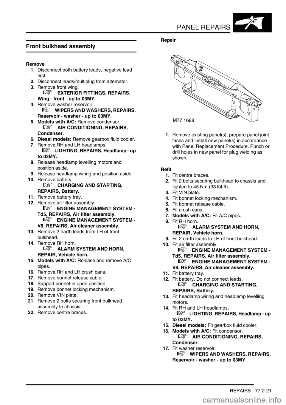
1.Remove existing panel(s), prepare panel joint
faces and install new panel(s) in accordance
with Panel Replacement Procedure. Punch or
drill holes in new panel for plug welding as
shown.
Refit
1.Fit centre braces.
2.Fit 2 bolts securing bulkhead to chassis and
tighten to 45 Nm (33 lbf.ft).
3.Fit VIN plate.
4.Fit bonnet locking mechanism.
5.Fit bonnet release cable.
6.Fit crush cans.
7. Models with A/C: Fit A/C pipes.
8.Fit RH horn.
+ ALARM SYSTEM AND HORN,
REPAIR, Vehicle horn.
9.Fit 2 earth leads to LH of front bulkhead.
10.Fit air filter assembly.
+ ENGINE MANAGEMENT SYSTEM -
Td5, REPAIRS, Air filter assembly.
+ ENGINE MANAGEMENT SYSTEM -
V8, REPAIRS, Air cleaner assembly.
11.Fit battery tray.
12.Fit battery. Do not connect leads.
+ CHARGING AND STARTING,
REPAIRS, Battery.
13.Fit headlamp wiring and headlamp levelling
motors.
14.Fit RH and LH headlamps.
+ LIGHTING, REPAIRS, Headlamp - up
to 03MY.
15. Diesel models: Fit gearbox fluid cooler.
16. Models with A/C: Fit condensor.
+ AIR CONDITIONING, REPAIRS,
Condenser.
17.Fit washer reservoir.
+ WIPERS AND WASHERS, REPAIRS,
Reservoir - washer - up to 03MY.
Page 1272 of 1672
PANEL REPAIRS
REPAIRS 77-2-23
Repair
1.Remove existing panel(s), prepare panel joint
faces and install new panel(s) in accordance
with Panel Replacement Procedure. Punch or
drill holes in new panel for plug welding as
shown.
Refit
1.Fit centre braces.
2.Fit VIN plate.
3.Fit bonnet locking mechanism.
4.Fit bonnet release cable.
5.Fit RH horn.
+ ALARM SYSTEM AND HORN,
REPAIR, Vehicle horn.
6.Fit air filter assembly.
+ ENGINE MANAGEMENT SYSTEM -
Td5, REPAIRS, Air filter assembly.
+ ENGINE MANAGEMENT SYSTEM -
V8, REPAIRS, Air cleaner assembly.
7.Fit battery tray.
8.Fit battery. Do not connect leads.
+ CHARGING AND STARTING,
REPAIRS, Battery.
9.Fit headlamp wiring.
10.Fit RH and LH repeater lamps.
+ LIGHTING, REPAIRS, Lamp - front
repeater.
11.Fit RH and LH headlamps.
+ LIGHTING, REPAIRS, Headlamp - up
to 03MY.
12. Diesel models: Fit gearbox fluid cooler.
13. Models with A/C: Fit condensor.
+ AIR CONDITIONING, REPAIRS,
Condenser.
14.Fit bumper assembly.
+ EXTERIOR FITTINGS, REPAIRS,
Bumper assembly - front.
15.Connect leads/multiplug to alternator.
16.Connect battery leads, negative lead last.
Front cross member
Remove
1.Disconnect both battery leads, negative lead
first.
2.Disconnect leads/multiplug from alternator.
3.Remove washer reservoir.
+ WIPERS AND WASHERS, REPAIRS,
Reservoir - washer - up to 03MY.
4. Models with A/C: Remove condensor.
+ AIR CONDITIONING, REPAIRS,
Condenser.
5. Diesel models: Remove gearbox fluid cooler.
6.Remove RH and LH headlamps.
+ LIGHTING, REPAIRS, Headlamp - up
to 03MY.
7.Release headlamp levelling motors and
position aside.
8.Release headlamp wiring and position aside.
9.Remove RH horn.
+ ALARM SYSTEM AND HORN,
REPAIR, Vehicle horn.
10. Models with A/C: Release and remove A/C
pipes.
11.Remove RH and LH crush cans.
12.Remove 2 bolts securing front bulkhead
assembly to chassis.
13.Remove centre braces.
Repair
1.Remove existing panel(s), prepare panel joint
faces and install new panel(s) in accordance
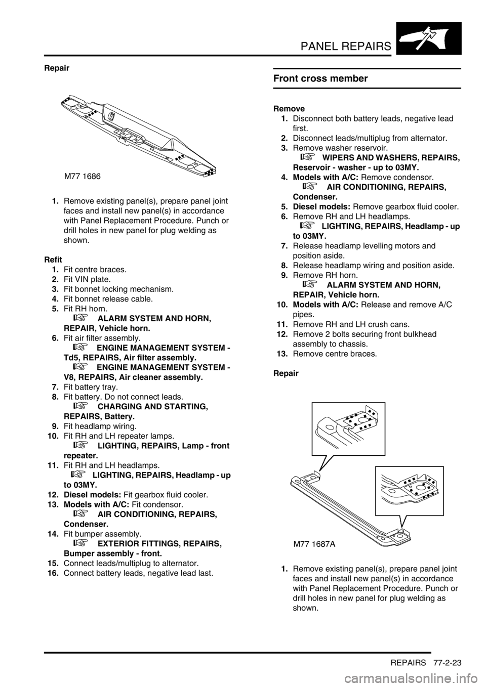
with Panel Replacement Procedure. Punch or
drill holes in new panel for plug welding as
shown.