Page 1175 of 1672

INTERIOR TRIM COMPONENTS
76-3-22 REPAIRS
38.Remove 7 nuts securing each stowage pocket
to headlining and collect mounting plates.
39.Remove both pockets from headlining.
40.Remove 8 screws securing rear console to
headlining and collect 3 mounting plates.
41.Remove rear console from headlining.
Refit
1.Fit rear console and mounting plates to
headlining.
2.Fit and tighten nuts securing rear console to
headlining.
3.Fit both stowage pockets and mounting plates
to headlining.
4.Fit and tighten nuts securing stowage pockets
to headlining.
5. Models with rear A/C:
aFit 3 central air vents to headlining.
bFit 2 rear air vents to headlining.
cFit foam pads to air vents.
6.With assistance, position headlining in vehicle.
7.Fit and tighten screw securing centre of
headlining to roof.
8.Connect multiplug to rear sunroof switch.
9.Fit rear sunroof switch to rear console.
10.Fit clips securing rear edge of headlining to
sunroof. 11.Position rear interior lamp to headlining and
connect multiplug.
12.Fit rear interior lamp to headlining.
13. Models with rear A/C:
aPosition rear A/C control panel to headlining
and connect multiplugs and Lucar
connectors.
bFit rear A/C control panel to headlining.
14. Models with volumetric alarm: Connect
multiplug to front volumetric sensor and fit
sensor to headlining.
15.Fit grab handles to headlining and secure with
bolts.
16.Fit end caps to grab handles.
17.Fit front sunroof aperture trim.
18.Fit rear sunroof aperture trim.
19.Fit tail door aperture upper trim casing.
20.Fit sun visor clips to headlining and secure with
screws.
21.Fit caps to sun visor clips.
22.Position front stowage pocket to headlining and
connect multiplugs to sunroof switches.
23.Fit and tighten 10 screws securing front
stowage pocket to headlining.
24.Connect multiplug to front interior lamp.
25.Fit front interior lamp to headlining and secure
with nuts.
26.Fit lens to front interior lamp.
27.Fit and tighten screw securing front stowage
pocket to headlining.
28.Fit access panel to front edge of front stowage
pocket.
29.Position sun visor to headlining and secure to
clip.
30.Connect multiplug to sun visor.
31.Fit and tighten screws securing sun visor to
headlining.
32.Repeat process for second sun visor.
33. Models with premium ICE: Position both 'A'
post trim casings and connect multiplugs to
speakers.
34.Fit both trim casings to 'A' posts and secure
with clips.
35.Fit both 'B' post upper trim casings.
+ INTERIOR TRIM COMPONENTS,
REPAIRS, Trim casing - upper - 'B' post.
36.Fit both 'D' post trim casings.
+ INTERIOR TRIM COMPONENTS,
REPAIRS, Trim casing - 'D' post.
Page 1176 of 1672

INTERIOR TRIM COMPONENTS
REPAIRS 76-3-23
Stowage pocket - front
$% 76.67.26
Remove
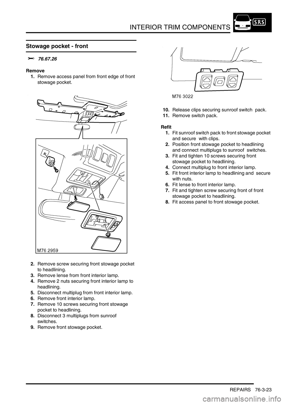
1.Remove access panel from front edge of front
stowage pocket.
2.Remove screw securing front stowage pocket
to headlining.
3.Remove lense from front interior lamp.
4.Remove 2 nuts securing front interior lamp to
headlining.
5.Disconnect multiplug from front interior lamp.
6.Remove front interior lamp.
7.Remove 10 screws securing front stowage
pocket to headlining.
8.Disconnect 3 multiplugs from sunroof
switches.
9.Remove front stowage pocket. 10.Release clips securing sunroof switch pack.
11.Remove switch pack.
Refit
1.Fit sunroof switch pack to front stowage pocket
and secure with clips.
2.Position front stowage pocket to headlining
and connect multiplugs to sunroof switches.
3.Fit and tighten 10 screws securing front
stowage pocket to headlining.
4.Connect multiplug to front interior lamp.
5.Fit front interior lamp to headlining and secure
with nuts.
6.Fit lense to front interior lamp.
7.Fit and tighten screw securing front of front
stowage pocket to headlining.
8.Fit access panel to front stowage pocket.
Page 1180 of 1672

SCREENS
REPAIRS 76-4-3
10.From outside of vehicle, use a Kent knife and
carefully cut through sealant securing sides of
screen to body.
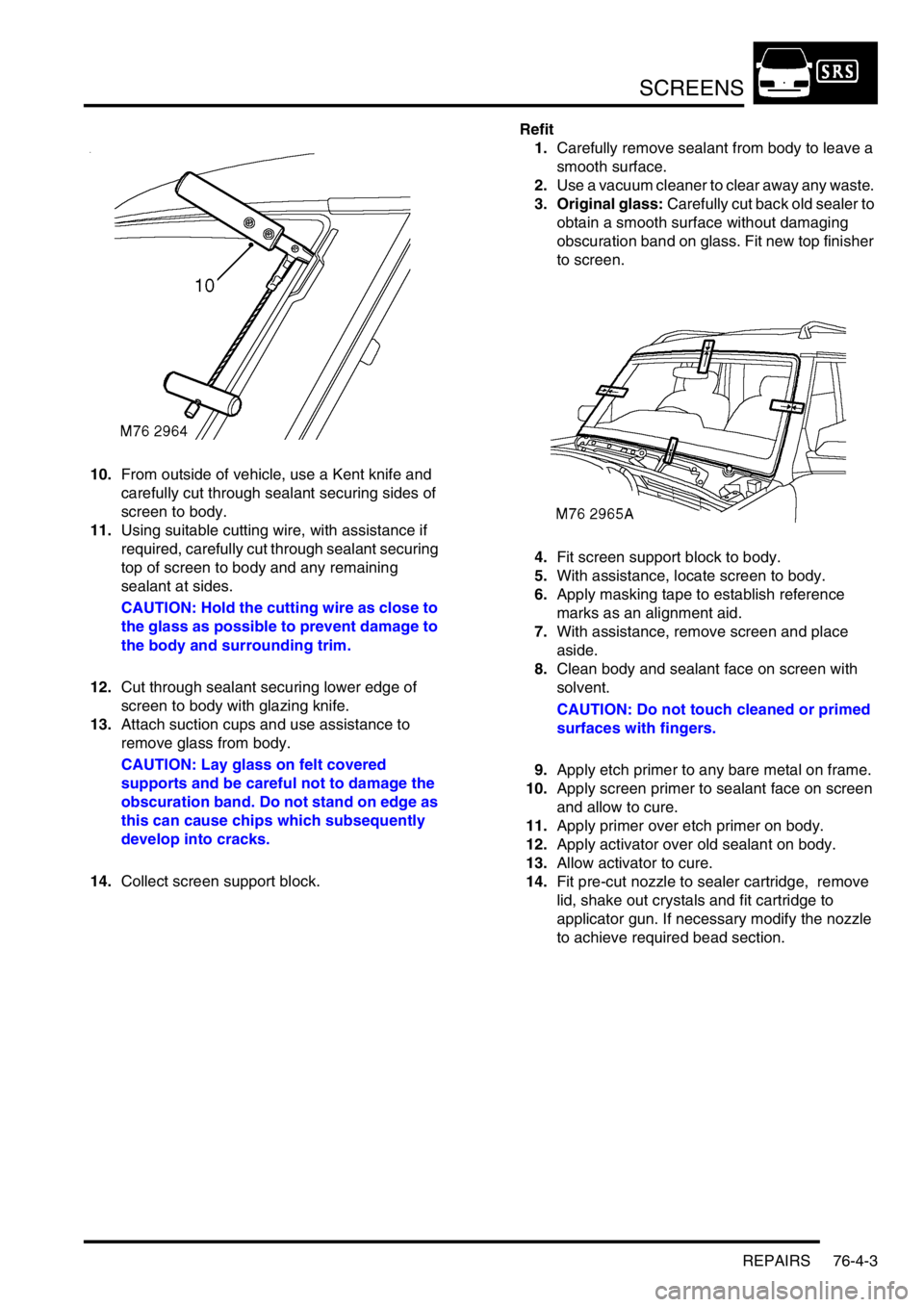
11.Using suitable cutting wire, with assistance if
required, carefully cut through sealant securing
top of screen to body and any remaining
sealant at sides.
CAUTION: Hold the cutting wire as close to
the glass as possible to prevent damage to
the body and surrounding trim.
12.Cut through sealant securing lower edge of
screen to body with glazing knife.
13.Attach suction cups and use assistance to
remove glass from body.
CAUTION: Lay glass on felt covered
supports and be careful not to damage the
obscuration band. Do not stand on edge as
this can cause chips which subsequently
develop into cracks.
14.Collect screen support block. Refit
1.Carefully remove sealant from body to leave a
smooth surface.
2.Use a vacuum cleaner to clear away any waste.
3. Original glass: Carefully cut back old sealer to
obtain a smooth surface without damaging
obscuration band on glass. Fit new top finisher
to screen.
4.Fit screen support block to body.
5.With assistance, locate screen to body.
6.Apply masking tape to establish reference
marks as an alignment aid.
7.With assistance, remove screen and place
aside.
8.Clean body and sealant face on screen with
solvent.
CAUTION: Do not touch cleaned or primed
surfaces with fingers.
9.Apply etch primer to any bare metal on frame.
10.Apply screen primer to sealant face on screen
and allow to cure.
11.Apply primer over etch primer on body.
12.Apply activator over old sealant on body.
13.Allow activator to cure.
14.Fit pre-cut nozzle to sealer cartridge, remove
lid, shake out crystals and fit cartridge to
applicator gun. If necessary modify the nozzle
to achieve required bead section.
Page 1182 of 1672

SCREENS
REPAIRS 76-4-5
6.From outside of vehicle, use a Kent knife and
carefully cut through sealant to release glass
from body. Any remaining sealant not
accessible with Kent knife can be severed
using cutting wire or knife.
CAUTION: Hold the cutting wire as close to
the glass as possible to prevent damage to
the body and surrounding trim.
7.Remove glass.
CAUTION: Lay glass on felt covered
supports and be careful not to damage the
obscuration band. Do not stand on edge as
this can cause chips which subsequently
develop into cracks.
Refit
1.Carefully remove sealant from body to leave a
smooth surface.
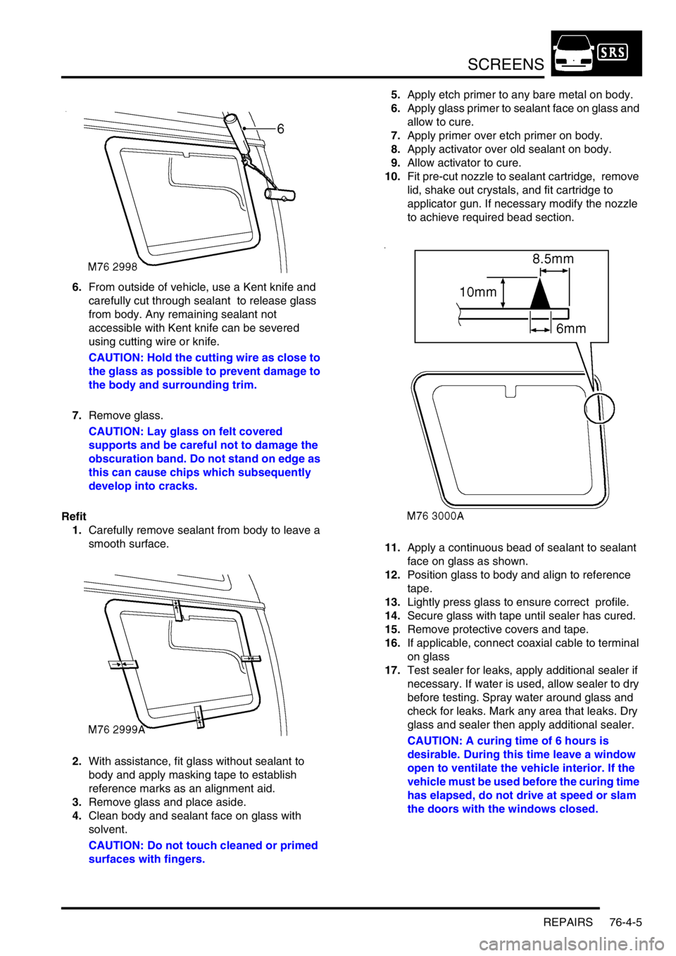
2.With assistance, fit glass without sealant to
body and apply masking tape to establish
reference marks as an alignment aid.
3.Remove glass and place aside.
4.Clean body and sealant face on glass with
solvent.
CAUTION: Do not touch cleaned or primed
surfaces with fingers.5.Apply etch primer to any bare metal on body.
6.Apply glass primer to sealant face on glass and
allow to cure.
7.Apply primer over etch primer on body.
8.Apply activator over old sealant on body.
9.Allow activator to cure.
10.Fit pre-cut nozzle to sealant cartridge, remove
lid, shake out crystals, and fit cartridge to
applicator gun. If necessary modify the nozzle
to achieve required bead section.
11.Apply a continuous bead of sealant to sealant
face on glass as shown.
12.Position glass to body and align to reference
tape.
13.Lightly press glass to ensure correct profile.
14.Secure glass with tape until sealer has cured.
15.Remove protective covers and tape.
16.If applicable, connect coaxial cable to terminal
on glass
17.Test sealer for leaks, apply additional sealer if
necessary. If water is used, allow sealer to dry
before testing. Spray water around glass and
check for leaks. Mark any area that leaks. Dry
glass and sealer then apply additional sealer.
CAUTION: A curing time of 6 hours is
desirable. During this time leave a window
open to ventilate the vehicle interior. If the
vehicle must be used before the curing time
has elapsed, do not drive at speed or slam
the doors with the windows closed.
Page 1184 of 1672
SCREENS
REPAIRS 76-4-7
12.Position glass to body and align to reference
tape.
13.Lightly press glass to ensure correct profile.
14.Secure glass with tape until sealer has cured.
15.Remove protective covers and tape.
16.Test sealer for leaks, apply additional sealer if
necessary. If water is used, allow sealer to dry
before testing. Spray water around glass and
check for leaks. Mark any area that leaks. Dry
glass and sealer then apply additional sealer.
CAUTION: A curing time of 6 hours is
desirable. During this time leave a window
open to ventilate the vehicle interior. If the
vehicle must be used before the curing time
has elapsed, do not drive at speed or slam
the doors with the windows closed.
Page 1200 of 1672
SEATS
REPAIRS 76-5-15
REPAIRS
Seat - front
$% 78.10.43.99
Remove
1.Disconnect battery earth lead.
2.Remove 3 screws and 1 trim clip securing
lower trim casing to seat.
3.Remove lower trim casing.
4.Remove cap from front seat belt lower
anchorage bolt.
5.Remove front seat belt lower anchorage bolt. 6.Remove 4 Torx bolts and nut securing front
seat to floor.
7.Lean seat forward to gain access to multiplugs.
Page 1201 of 1672
SEATS
76-5-16 REPAIRS
8.Release pretensioner multiplug from seat
frame and disconnect.
9. Electrically operated seats: Disconnect 2
seat motor multiplugs.
10.Remove front seat.
Refit
1.Fit front seat in vehicle.
2. Electrically operated seats: Connect seat
motor multiplugs.
3.Connect pretensioner multiplug and secure to
seat frame.
4.Fit Torx bolts and nut securing front seat to floor
and tighten to 45 Nm (33 lbf.ft).
5.Fit front seat belt lower anchorage bolt to front
seat and tighten to 32 Nm (24 lbf.ft).
6.Fit cap to lower anchorage bolt.
7.Fit lower trim casing to seat and secure with
screws and trim clip.
8.Connect battery earth lead.
Seat - third row
$% 78.10.45
Remove
1.Manufacture a spring retainer bracket to the
dimensions given above.
2.Position third row seat in deployed position.
3.Remove the cup holder (where applicable).
Page 1202 of 1672

SEATS
REPAIRS 76-5-17
4.Remove saddle bracket cover from lower rear
quarter to allow access to third row seat
securing bolts and nuts.
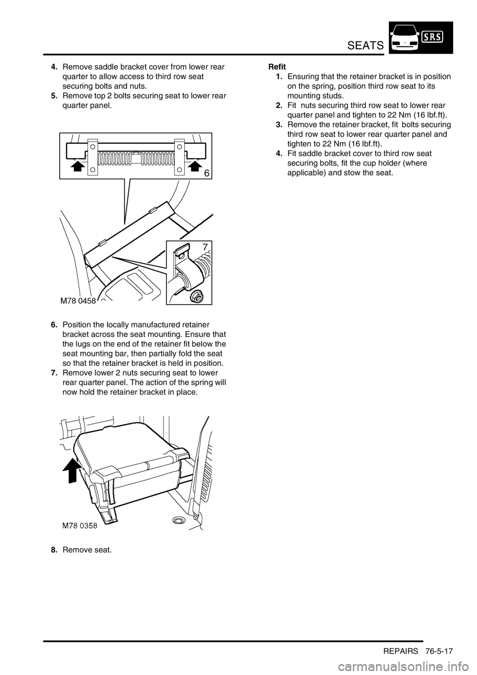
5.Remove top 2 bolts securing seat to lower rear
quarter panel.
6.Position the locally manufactured retainer
bracket across the seat mounting. Ensure that
the lugs on the end of the retainer fit below the
seat mounting bar, then partially fold the seat
so that the retainer bracket is held in position.
7.Remove lower 2 nuts securing seat to lower
rear quarter panel. The action of the spring will
now hold the retainer bracket in place.
8.Remove seat.Refit
1.Ensuring that the retainer bracket is in position
on the spring, position third row seat to its
mounting studs.
2.Fit nuts securing third row seat to lower rear
quarter panel and tighten to 22 Nm (16 lbf.ft).
3.Remove the retainer bracket, fit bolts securing
third row seat to lower rear quarter panel and
tighten to 22 Nm (16 lbf.ft).
4.Fit saddle bracket cover to third row seat
securing bolts, fit the cup holder (where
applicable) and stow the seat.