2002 LAND ROVER DISCOVERY cruise control
[x] Cancel search: cruise controlPage 1281 of 1672

PANEL REPAIRS
77-2-32 REPAIRS
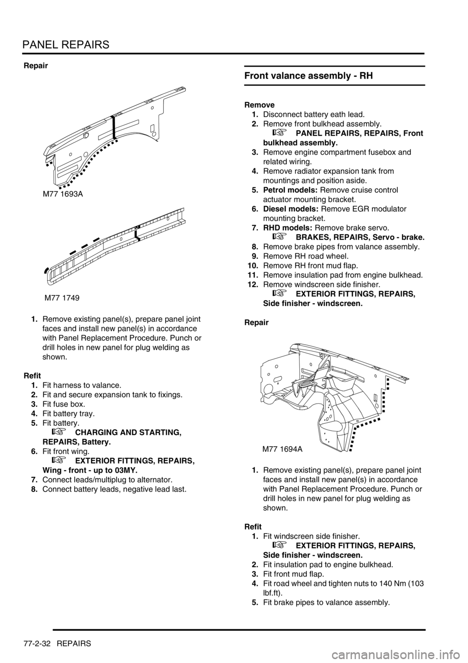
Repair
1.Remove existing panel(s), prepare panel joint
faces and install new panel(s) in accordance
with Panel Replacement Procedure. Punch or
drill holes in new panel for plug welding as
shown.
Refit
1.Fit harness to valance.
2.Fit and secure expansion tank to fixings.
3.Fit fuse box.
4.Fit battery tray.
5.Fit battery.
+ CHARGING AND STARTING,
REPAIRS, Battery.
6.Fit front wing.
+ EXTERIOR FITTINGS, REPAIRS,
Wing - front - up to 03MY.
7.Connect leads/multiplug to alternator.
8.Connect battery leads, negative lead last.
Front valance assembly - RH
Remove
1.Disconnect battery eath lead.
2.Remove front bulkhead assembly.
+ PANEL REPAIRS, REPAIRS, Front
bulkhead assembly.
3.Remove engine compartment fusebox and
related wiring.
4.Remove radiator expansion tank from
mountings and position aside.
5. Petrol models: Remove cruise control
actuator mounting bracket.
6. Diesel models: Remove EGR modulator
mounting bracket.
7. RHD models: Remove brake servo.
+ BRAKES, REPAIRS, Servo - brake.
8.Remove brake pipes from valance assembly.
9.Remove RH road wheel.
10.Remove RH front mud flap.
11.Remove insulation pad from engine bulkhead.
12.Remove windscreen side finisher.
+ EXTERIOR FITTINGS, REPAIRS,
Side finisher - windscreen.
Repair
1.Remove existing panel(s), prepare panel joint
faces and install new panel(s) in accordance
with Panel Replacement Procedure. Punch or
drill holes in new panel for plug welding as
shown.
Refit
1.Fit windscreen side finisher.
+ EXTERIOR FITTINGS, REPAIRS,
Side finisher - windscreen.
2.Fit insulation pad to engine bulkhead.
3.Fit front mud flap.
4.Fit road wheel and tighten nuts to 140 Nm (103
lbf.ft).
5.Fit brake pipes to valance assembly.
M77 1693A
M77 1749
M77 1694A
Page 1282 of 1672

PANEL REPAIRS
REPAIRS 77-2-33
6. RHD models: Fit brake servo.
7. Diesel models: Fit EGR modulator mounting
bracket.
8. Petrol models: Fit cruise control actuator
mounting bracket.
9.Fit radiator expansion tank.
10.Fit fusebox and secure wiring.
11.Fit front bulkhead assembly.
+ PANEL REPAIRS, REPAIRS, Front
bulkhead assembly.
12.Connect battery leads, negative lead last.
Front valance assembly - LH
Remove
1.Disconnect both battery leads, negative lead
first.
2.Disconnect leads/multiplug from alternator.
3.Remove front bulkhead assembly.
+ PANEL REPAIRS, REPAIRS, Front
bulkhead assembly.
4.Remove ABS modulator unit.
+ BRAKES, REPAIRS, Modulator unit
- ABS.
5. LHD models: Remove brake servo.
+ BRAKES, REPAIRS, Servo - brake.
6.Remove brake pipes from valance assembly.
7.Remove PAS/ACE reservoir.
8. Models with A/C: Remove A/C pipes from
valance assembly.
9.Remove wiring harness from valance
assembly.
10.Remove LH front road wheel.
11.Remove LH front mud flap.
12.Remove insulation pad from engine bulkhead.
13.Remove windscreen side finisher.
+ EXTERIOR FITTINGS, REPAIRS,
Side finisher - windscreen.
Repair
1.Remove existing panel(s), prepare panel joint
faces and install new panel(s) in accordance
with Panel Replacement Procedure. Punch or
drill holes in new panel for plug welding as
shown.
M77 1742
Page 1485 of 1672

BODY CONTROL UNIT
86-3-16 DESCRIPTION AND OPERATION
Headlamps
The BCU contains a feature which allow the vehicle headlamps to be turned on when the remote transmitter is
pressed (courtesy headlamps).
For markets with daylight running lamps, the BCU controls the logical operation of the daylight running lamps. Options
are daylight running lamps are on if the main beam headlamps are off, or the daylight running lamps are on with main
and dipped beam off and the gearbox not in Park.
Front fog lamps
For markets with front fog lamps fitted, the BCU controls the operation of the front fog lamps. Options can be selected
so that the fog lamps will operate with or without the headlamps on main beam.
Instrument pack
The BCU communicates with the instrument pack via a serial data bus.
+ INSTRUMENTS, DESCRIPTION AND OPERATION, Description.
lThe instrument pack provides the BCU and IDM with details of vehicle speed.
lSignals are provided from the IDM to the instrument pack and BCU when the direction indicator lamps are active.
lFor certain markets, the BCU provides a signal to the instrument pack for indicating when the transfer box is in
neutral.
lThe IDM can signal the instrument pack to illuminate a trailer warning lamp. This operates when the IDM senses
that the current drawn by the indicator circuit exceeds a preset threshold.
lThe odometer reading displayed on the instrument pack LCD screen is also stored in non volatile memory in the
BCU. Whenever the ignition is turned from position I to position II, the instrument pack and the BCU compare
their stored values.
lThe gear selector position is displayed on the instrument pack LCD screen under the direction of the BCU.
Starting
The starting system comprises a starter motor and solenoid located at the rear right hand side of the engine. A starter
relay controlled by the BCU is used to supply battery power for starter solenoid operation. The starter motor receives
its feed directly from the battery.
Cruise control
The BCU processes several signals used for cruise control:
lWhen the brake pedal is pressed, a low voltage brake lamp signal is sent via the BCU to the cruise control ECU.
lThe gear position switch sends an input via the BCU to the cruise control ECU if the selector lever is in Park,
Neutral or Reverse.
lA voltage supply is fed from the BCU to the cruise control SET+ switch.
lA voltage supply is fed from the BCU to the cruise control RES switch.
On vehicles with automatic transmission, if the BCU receives an input from the gear position switch or the brake pedal
switch, the BCU sends a signal to the cruise control ECU to cancel or inhibit cruise control operation.
+ ENGINE MANAGEMENT SYSTEM - Td5, DESCRIPTION AND OPERATION, Description.
+ ENGINE MANAGEMENT SYSTEM - V8, DESCRIPTION AND OPERATION, Description - cruise control.
Shift interlock (where fitted)
On automatic gearbox models, the BCU and IDM combine with an interlock relay located in the passenger
compartment fuse box to operate a shift interlock solenoid, so that the gear selector lever cannot be moved out of
Park until certain logical conditions have been satisfied. Operation of the interlock may be affected, if the battery
becomes discharged.
+ AUTOMATIC GEARBOX - ZF4HP22 - 24, DESCRIPTION AND OPERATION, Description.
Page 1502 of 1672

BODY CONTROL UNIT
DESCRIPTION AND OPERATION 86-3-33
Cruise control
The Neutral/ Reverse/ Park/ Brake selected output is used by the cruise control system. The BCU checks for the
following inputs:
lIgnition on.
lGearbox state.
lBrake switch activated.
For vehicles with manual transmission, Neutral/ Reverse/ Park/ Brake selected output is on if the ignition is on and
brake switch activated is on. Otherwise, the Neutral/ Reverse/ Park/ Brake selected output is off.
For vehicles with automatic transmission, the Neutral/ Reverse/ Park/ Brake selected output is on if the ignition is on
and brake switch activated is on, or if the ignition is on and 'gearbox state' is in Neutral, Park or Reverse. Otherwise
Neutral/ Reverse/ Park/ Brake selected output is off.
Shift interlock (where fitted)
On automatic gearbox models, the BCU and IDM combine to operate a shift interlock solenoid, so that the gear
selector lever can only be moved when certain logical conditions have been satisfied. Operation of the interlock may
be affected, if the battery becomes discharged.
+ AUTOMATIC GEARBOX - ZF4HP22 - 24, DESCRIPTION AND OPERATION, Description.
When the gear selector lever is in the Park position and the ignition is off, an interlock solenoid is de-energised, locking
the gear selector lever in the Park position.
The gear selector lever can only be moved from the Park position when the ignition is switched on and the brake pedal
is depressed. When these conditions are satisfied, the brake pedal switch signal is received by the BCU which then
signals the IDM to energise the interlock relay. When the interlock relay is energised, the interlock solenoid is
operated, unlocking the gear selector lever.
When the brake pedal is released, the feed to the BCU is removed and the shift interlock solenoid is de-energised.
The locking mechanism controlled by the solenoid will lock the gear selector lever once it is returned to the Park
position.
The shift interlock option can be programmed in one of three states dependent on market/ customer requirements,
these are:
lOption 1– not fitted.
lOption 2 – normal operation.
lOption 3 – inhibit transfer box.
The BCU checks the status of the following inputs to determine the logic action for employing the shift interlock
solenoid:
lBrake switch activated.
lIgnition state.
lGearbox state.
In the event of a communications link failure, the shift interlock solenoid enable is switched on for 1 minute every time
the ignition is switched on and switched off when the ignition is turned off.
Ignition interlock (where fitted)
On automatic gearbox models, when the ignition key is inserted in the ignition switch, the ignition key-in switch
contacts close to supply a signal to the BCU to indicate the presence of the key in the switch and provide a supply
feed to the ignition interlock solenoid. If the gear selector lever is in a position other than Park, or the 'transfer box
neutral selected' is on, the BCU will supply an earth path to complete the ignition interlock circuit and cause the
interlock solenoid to be engaged. With the interlock solenoid engaged, removal of the ignition key is prevented. The
BCU will open the circuit, to allow removal of the ignition key, only when the gear selector lever is in the Park position
and the transfer box is in either high or low range.
Page 1590 of 1672

HARNESSES
REPAIRS 86-7-19
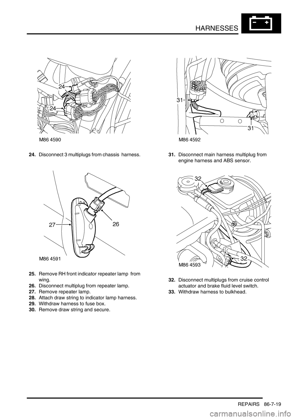
24.Disconnect 3 multiplugs from chassis harness.
25.Remove RH front indicator repeater lamp from
wing.
26.Disconnect multiplug from repeater lamp.
27.Remove repeater lamp.
28.Attach draw string to indicator lamp harness.
29.Withdraw harness to fuse box.
30.Remove draw string and secure.31.Disconnect main harness multiplug from
engine harness and ABS sensor.
32.Disconnect multiplugs from cruise control
actuator and brake fluid level switch.
33.Withdraw harness to bulkhead.
Page 1596 of 1672

HARNESSES
REPAIRS 86-7-25
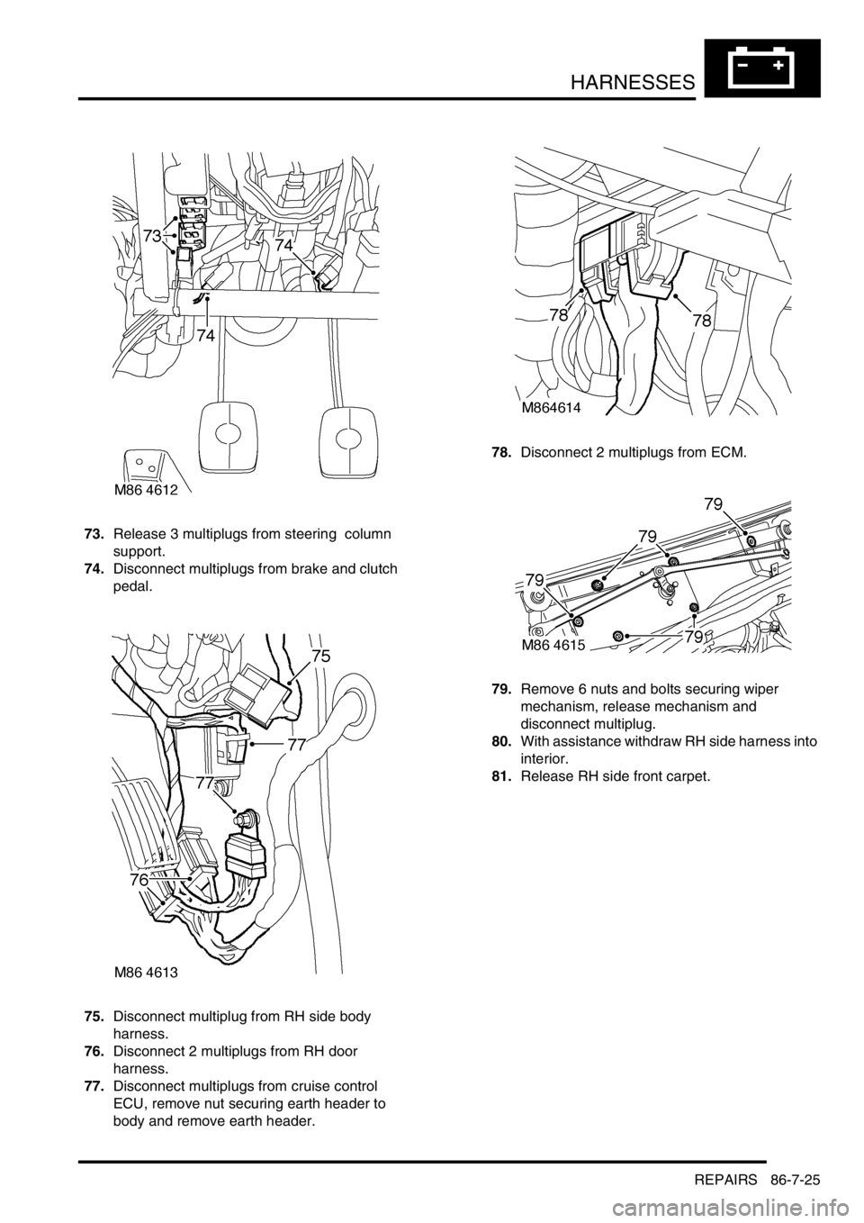
73.Release 3 multiplugs from steering column
support.
74.Disconnect multiplugs from brake and clutch
pedal.
75.Disconnect multiplug from RH side body
harness.
76.Disconnect 2 multiplugs from RH door
harness.
77.Disconnect multiplugs from cruise control
ECU, remove nut securing earth header to
body and remove earth header. 78.Disconnect 2 multiplugs from ECM.
79.Remove 6 nuts and bolts securing wiper
mechanism, release mechanism and
disconnect multiplug.
80.With assistance withdraw RH side harness into
interior.
81.Release RH side front carpet.
Page 1598 of 1672

HARNESSES
REPAIRS 86-7-27
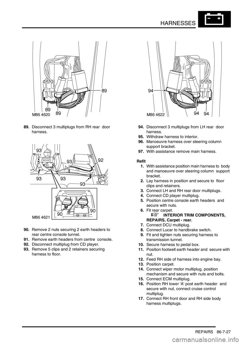
89.Disconnect 3 multiplugs from RH rear door
harness.
90.Remove 2 nuts securing 2 earth headers to
rear centre console tunnel.
91.Remove earth headers from centre console.
92.Disconnect multiplug from CD player.
93.Remove 5 clips and 2 retainers securing
harness to floor. 94.Disconnect 3 multiplugs from LH rear door
harness.
95.Withdraw harness to interior.
96.Manoeuvre harness over steering column
support bracket.
97.With assistance remove main harness.
Refit
1.With assistance position main harness to body
and manoeuvre over steering column support
bracket.
2.Lay harness in position and secure to floor
clips and retainers.
3.Connect LH and RH rear door multiplugs.
4.Connect CD player multiplug.
5.Position centre console earth headers and
secure with nuts.
6.Fit rear carpet.
+ INTERIOR TRIM COMPONENTS,
REPAIRS, Carpet - rear.
7.Connect DCU multiplug.
8.Connect Lucar to handbrake switch.
9.Fit and tighten nuts securing harness to
transmission tunnel.
10.Secure harness to pedal box.
11.Position footwell earth header and secure with
nut.
12.Feed RH side of harness into engine bay.
13.Position carpet.
14.Connect wiper motor multiplug, position
mechanism and secure with nuts and bolts.
15.Connect ECM multiplug.
16.Position RH lower 'A' post earth header and
secure with nut, connect cruise control
multiplug.
17.Connect RH front door and RH side body
harness multiplugs.
Page 1599 of 1672

HARNESSES
86-7-28 REPAIRS
18.Secure multiplugs to steering column support
bracket and connect brake and clutch pedal
multiplugs.
19.Connect multiplugs to column switch and
passive coil.
20.Position passenger compartment fusebox,
connect multiplugs, fit fusebox to fascia and
secure with nut.
21.Connect ignition switch multiplug to fuse box.
22.With assistance feed LH side of harness into
engine bay.
23.Connect multiplugs to front door harness and
body harness.
24.Position earth headers to LH lower 'A' post and
secure with nuts.
25.Connect multiplugs to ECU pack.
26.Position harness in engine bay.
27.Connect and secure heated front screen
multiplugs.
28.Fit plenum molding.
+ HEATING AND VENTILATION,
REPAIRS, Plenum Air Intake.
29.Connect multiplugs to ABS sensor and fuel
cut-off switch.
30.Using draw string feed harness through inner
wing, remove draw string, connect repeater
lamp multiplug and fit lamp.
31.Connect multiplugs to ABS modulator.
32.Feed harness through to front panel.
33.Position body earth leads and secure with
bolts.
34.Connect washer reservoir multiplugs and
pipes, secure pipes with clips.
35.Secure fog lamp multiplug.
36.Secure earth header behind headlamp.
37.Connect multiplugs to headlamp level motor,
headlamp and side lamp.
38.Fit indicator lamp
+ LIGHTING, REPAIRS, Lamp - front
repeater.
39.Connect multiplug to LH horn.
40.Feed harness to ACE accelerometer, connect
multiplug and secure with cable ties.
41.Connect cruise control, ABS sensor and brake
fluid level switch multiplugs.
42.Connect engine harness multiplug and feed
harness along RH wing to fuse box.
43.Using draw string pull harness through inner
wing, remove draw string, connect repeater
lamp multiplug and fit lamp. 44.Connect chassis harness multiplugs.
45.Position engine bay fuse box and connect
multiplugs, fit fuse box and secure with screws.
46.Connect multiplugs to front of fuse box.
47.Position battery and starter cables and secure
with screws.
48.Fit fuse box cover.
49.Position earth lead and secure with nut.
50.Feed harness through to front panel.
51.Secure fog lamp multiplug.
52.Connect headlamp level motor, headlamp and
side lamp multiplugs.
53.Fit indicator lamp.
+ LIGHTING, REPAIRS, Lamp - front
repeater.
54.Secure harness to RH front panel.
55.Connect cooling fan and horn multiplug.
56.Secure harness to lower support rail.
57.Connect receiver drier and air temperature
sensor multiplugs.
58.Fit front bumper.
+ EXTERIOR FITTINGS, REPAIRS,
Bumper assembly - front.
59.Fit battery tray.
60.Fit air filter assembly.
+ ENGINE MANAGEMENT SYSTEM -
V8, REPAIRS, Air cleaner assembly.
61.Position both lower 'A' post trims and secure
with studs.
62.Fit heater assembly.
+ HEATING AND VENTILATION,
REPAIRS, Heater assembly - models with
air conditioning.
+ HEATING AND VENTILATION,
REPAIRS, Heater assembly - models
without air conditioning.