2002 LAND ROVER DISCOVERY oil type
[x] Cancel search: oil typePage 877 of 1672

FRONT AXLE
54-4 DESCRIPTION AND OPERATION
Drive shaft
Each drive shaft consists of a solid rod, splined at both ends, with a constant velocity joint installed on the outboard
end. A shield is incorporated onto each rod to protect the oil seals in the axle casing. The constant velocity joint is of
the ball and socket type. A shaft on the constant velocity joint is splined to the hub flange. The constant velocity joint
is pre-packed with grease and protected by a gaiter. Two securing bands retain the gaiter in position.
Page 1012 of 1672

REAR SUSPENSION
DESCRIPTION AND OPERATION 64-7
Coil springs (vehicles without SLS)
On vehicles without SLS fitted, coil springs are fitted between the rear axle and the chassis in place of the SLS air
springs. Each spring is located at its base by the lower spring seat which is secured to a fabricated platform on the
rear axle with two bolts. The top of each spring is located in the upper spring seat. The upper spring seat comprises
a pressed metal plate with an outer coating of natural rubber bonded to the plate. The upper spring seat is retained
in position by the compression of the spring.
Coil Spring Specifications – Models up to 03 Model Year
The rear coil springs are of the variable rate type and are manufactured from silicon manganese 16.5 mm (0.65 in.)
diameter bar. Each spring has 9 coils and a free length of 385 mm (15.1 in.). The variable rate of the spring is achieved
by the active coils at one end being closer together. The rear coil spring is identified by a purple stripe painted on a
number of coils.
Coil Spring Specifications – Models From 03 Model Year
The introduction of the 03MY vehicle introduced a range of additional rear coil spring fitments. These were introduced
as a package to optimise vehicle trim heights.
The coil springs are manufactured from silicon manganese 16.35 mm (0.64 in.) diameter bar for springs on five seater
models and 16.57 mm (0.65 in.) diameter bar on seven seater models. The following spring data table shows the
colour codes, number of coils and spring free length.
Spring Data
The following table shows spring fitment applicability.
Spring Fitment Applicability
Watts linkage
A Watts linkage is used to ensure that the rear axle remains centrally located. The Watts linkage comprises two
transverse links and a pivot housing. The transverse links and pivot housing allow the rear axle to move vertically
without any transverse movement.
The transverse links are made from fabricated and welded steel. Each transverse link has a bush press fitted into a
housing at one end. The opposite end has a forked bracket with two cross holes.
The pivot housing is made from cast iron. Three bushes are press fitted in the housing, one in the centre and one at
each end.
Colour Code Total No. of Coils Free Length Model
Brown/Orange 8.73 384.7 mm (15.14 in) 5 Seat
Grey/Orange 8.73 392 mm (15.43 in) 5 Seat
Yellow/Grey 8.73 376.6 mm (14.82 in) 5 Seat
Pink/Grey 8.73 400.3 mm (15.75 in) 5 Seat
Blue/Grey 9.10 387.8 mm (15.26 in) 7 Seat
Green/Grey 9.10 395.2 mm (15.55 in) 7 Seat
White/Grey 9.10 380.6 mm (14.98 in) 7 Seat
Left Hand Drive Right Hand Drive
Both Sides RH Side LH Side
Brown/Orange Grey/Orange Yellow/Grey
Grey Orange Pink/Grey Brown/Orange
Blue/Grey Green/Grey White/Grey
Page 1013 of 1672

REAR SUSPENSION
64-8 DESCRIPTION AND OPERATION
The pivot housing is located in a fabricated bracket centrally located on the rear of the axle. The central bush of the
pivot housing is secured in the bracket with a bolt and locknut. Fabricated brackets on each chassis longitudinal
provide for the attachment of each transverse link. Each link is secured through its bush with a bolt and locknut. The
forked end of each link locates over the bushes at each end of the pivot housing and is secured with a bolt and locknut.
The attachment bolts for each link are coated with a clear, dry wax which reduces friction on the bolt and allows the
correct torque to be applied to the clamping of the bushes. The bolts can be re-used, but if bolt replacement is
necessary the correct bolt with the wax coating must be used.
Anti-roll bar
The anti-roll bars fitted differ between ACE and non-ACE vehicles. On non-ACE vehicles a conventional 'passive' anti-
roll bar is used. On ACE vehicles an 'active' torsion bar is used. Both types are attached to the tubular cross-member
at the rear of the chassis with mounting rubbers and clamp plates. The clamp plates locate in fabricated brackets
attached to the tubular cross-member and secured with bolts.
Each end of the anti-roll bar is attached to an anti-roll bar link. Each link has a spherical bearing attached at each end.
One end is attached to a bracket on the axle and secured with a locknut. The opposite end attaches through a hole
in the anti-roll bar and is also secured with a locknut. On 'active' torsion bars, the RH anti-roll bar link is attached to a
long arm which in turn is attached to the anti-roll bar.
Passive anti-roll bar
The passive anti-roll bar is a conventional anti-roll bar which opposes axle movement, reducing the effects of lateral
forces on the vehicle body.
With the conventional passive anti-roll bar, axle movement is opposed by the anti-roll bar through links attached to
the axle casing and each end of the anti-roll bar.
On vehicles with coil springs (no SLS fitted) the anti-roll bar is manufactured from 19 mm (0.74 in.) diameter spring
steel bar.
On vehicles with air springs (SLS fitted) the anti-roll bar is manufactured from 29 mm (1.14 in.) diameter spring steel
bar.
Active torsion bar
+ FRONT SUSPENSION, DESCRIPTION AND OPERATION, Description - ACE.The 'active' torsion bar is
used in conjunction with the ACE system to control body roll and directional stability giving a reduction of the effects
of lateral forces on the vehicle body over a conventional 'passive' anti-roll bar.
The torsion bar opposes axle movement by the application of a hydraulic force to oppose the lateral forces through
links attached to the axle casing and each end of the bar. The torsion bar is made from 35 mm (1.4 in.) diameter spring
steel. One end is fitted with an arm which is operated by a hydraulic actuator to oppose corning forces.
Page 1055 of 1672

BRAKES
70-10 DESCRIPTION AND OPERATION
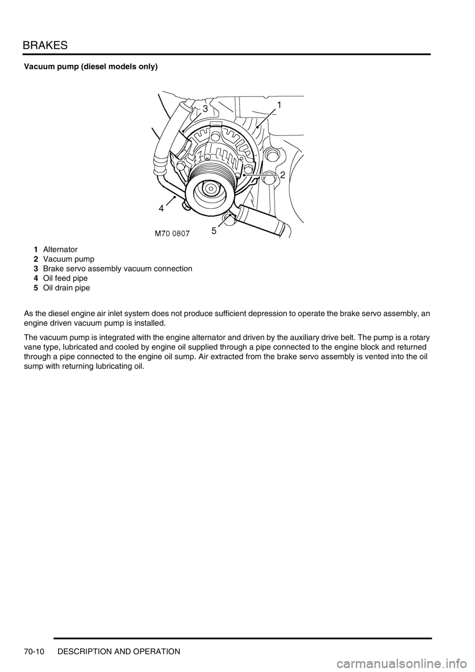
Vacuum pump (diesel models only)
1Alternator
2Vacuum pump
3Brake servo assembly vacuum connection
4Oil feed pipe
5Oil drain pipe
As the diesel engine air inlet system does not produce sufficient depression to operate the brake servo assembly, an
engine driven vacuum pump is installed.
The vacuum pump is integrated with the engine alternator and driven by the auxiliary drive belt. The pump is a rotary
vane type, lubricated and cooled by engine oil supplied through a pipe connected to the engine block and returned
through a pipe connected to the engine oil sump. Air extracted from the brake servo assembly is vented into the oil
sump with returning lubricating oil.
Page 1402 of 1672

AIR CONDITIONING
REFRIGERANT RECOVERY, RECYCLING AND RECHARGING 82-29
REFRIGERANT RECOVERY, RECYCLING AND RECHARGING
Refrigerant recovery, recycling and
recharging
$% 82.30.02
Recovery
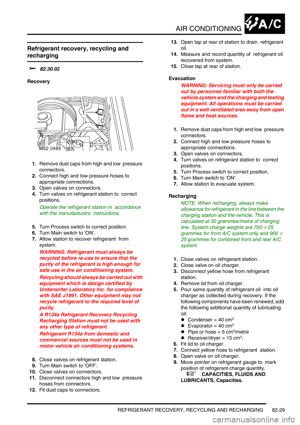
1.Remove dust caps from high and low pressure
connectors.
2.Connect high and low pressure hoses to
appropriate connections.
3.Open valves on connectors.
4.Turn valves on refrigerant station to correct
positions.
Operate the refrigerant station in accordance
with the manufacturers instructions.
5.Turn Process switch to correct position.
6.Turn Main switch to 'ON'.
7.Allow station to recover refrigerant from
system.
WARNING: Refrigerant must always be
recycled before re-use to ensure that the
purity of the refrigerant is high enough for
safe use in the air conditioning system.
Recycling should always be carried out with
equipment which is design certified by
Underwriter Laboratory Inc. for compliance
with SAE J1991. Other equipment may not
recycle refrigerant to the required level of
purity.
A R134a Refrigerant Recovery Recycling
Recharging Station must not be used with
any other type of refrigerant.
Refrigerant R134a from domestic and
commercial sources must not be used in
motor vehicle air conditioning systems.
8.Close valves on refrigerant station.
9.Turn Main switch to 'OFF'.
10.Close valves on connectors.
11.Disconnect connectors high and low pressure
hoses from connectors.
12.Fit dust caps to connectors. 13.Open tap at rear of station to drain refrigerant
oil.
14.Measure and record quantity of refrigerant oil
recovered from system.
15.Close tap at rear of station.
Evacuation
WARNING: Servicing must only be carried
out by personnel familiar with both the
vehicle system and the charging and testing
equipment. All operations must be carried
out in a well ventilated area away from open
flame and heat sources.
1.Remove dust caps from high and low pressure
connectors.
2.Connect high and low pressure hoses to
appropriate connections.
3.Open valves on connectors.
4.Turn valves on refrigerant station to correct
positions.
5.Turn Process switch to correct position.
6.Turn Main switch to 'ON'.
7.Allow station to evacuate system.
Recharging
NOTE: When recharging, always make
allowance for refrigerant in the line between the
charging station and the vehicle. This is
calculated at 30 grammes/metre of charging
line. System charge weights are 700
± 25
grammes for front A/C system only and 900
±
25 grammes for combined front and rear A/C
system.
1.Close valves on refrigerant station.
2.Close valve on oil charger.
3.Disconnect yellow hose from refrigerant
station.
4.Remove lid from oil charger.
5.Pour same quantity of refrigerant oil into oil
charger as collected during recovery. If the
following components have been renewed, add
the following additional quantity of lubricating
oil:
lCondenser = 40 cm
3
lEvaporator = 40 cm3
lPipe or hose = 5 cm3/metre
lReceiver/dryer = 15 cm3.
6.Fit lid to oil charger.
7.Connect yellow hose to refrigerant station.
8.Open valve on oil charger.
9.Move pointer on refrigerant gauge to mark
position of refrigerant charge quantity.
+ CAPACITIES, FLUIDS AND
LUBRICANTS, Capacities.
Page 1660 of 1672

INSTRUMENTS
DESCRIPTION AND OPERATION 88-33
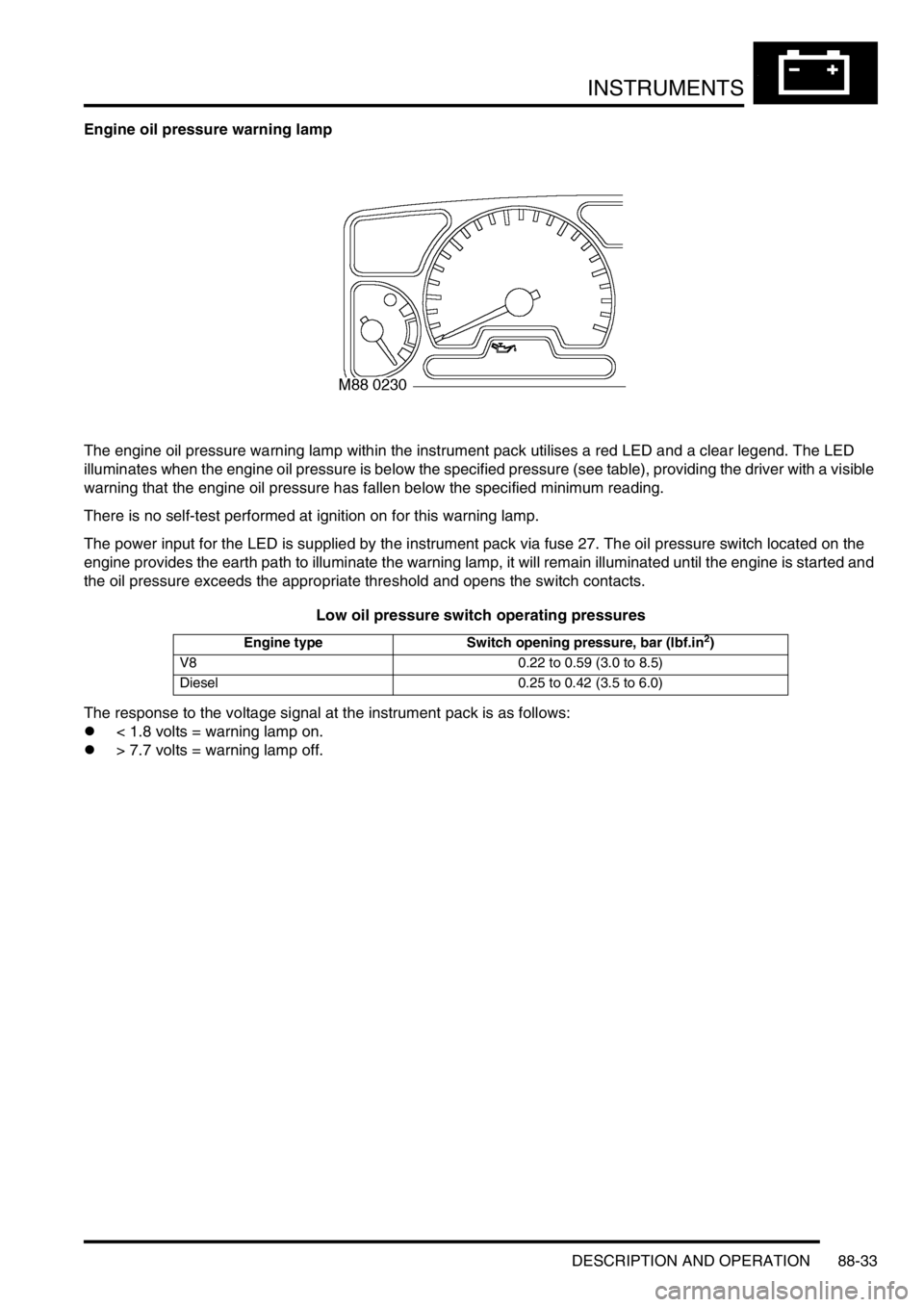
Engine oil pressure warning lamp
The engine oil pressure warning lamp within the instrument pack utilises a red LED and a clear legend. The LED
illuminates when the engine oil pressure is below the specified pressure (see table), providing the driver with a visible
warning that the engine oil pressure has fallen below the specified minimum reading.
There is no self-test performed at ignition on for this warning lamp.
The power input for the LED is supplied by the instrument pack via fuse 27. The oil pressure switch located on the
engine provides the earth path to illuminate the warning lamp, it will remain illuminated until the engine is started and
the oil pressure exceeds the appropriate threshold and opens the switch contacts.
Low oil pressure switch operating pressures
The response to the voltage signal at the instrument pack is as follows:
l< 1.8 volts = warning lamp on.
l> 7.7 volts = warning lamp off.
Engine type Switch opening pressure, bar (lbf.in2)
V8 0.22 to 0.59 (3.0 to 8.5)
Diesel 0.25 to 0.42 (3.5 to 6.0)