Page 1106 of 1672

RESTRAINT SYSTEMS
DESCRIPTION AND OPERATION 75-11
DESCRIPTION AND OPERAT ION
Description - seat belts
An inertia reel, three point seat belt is installed at each seat position. The inertia reels incorporate a liftshaft locking
system with webbing sensor and car sensor activating mechanisms. The webbing sensor activates the locking system
if the webbing is subjected to a sharp pull. The car sensor activates the locking system if the vehicle is subjected to
sudden deceleration or a severe tilt angle.
Front seat belts
The inertia reel of each front seat belt is attached to the related B/C post, behind the finishers. The webbing runs from
the inertia reel, through a height adjuster, to an anchor point at the base of the B/C post. The buckle assembly for
each belt is attached to the inboard side of the seat and contains the SRS pretensioner.
Rear seat belts
The inertia reels for the outboard rear seats are attached to the body behind the loadspace side trim casings. The
webbing runs from each inertia reel through an upper mounting, suspended from the cantrail, to an anchor point on
the rear wheel arch.
The inertia reel of the centre rear seat is mounted in the back of the seat. The webbing runs through a guide on the
top of the seat and is anchored to one of the seat hinge points. The buckles for the rear seat belts are also attached
to the seat hinge points.
Third row seat belts
The inertia reel of each third row rear seat belt is attached to the related E post, behind the loadspace side trim
casing.The webbing runs from the inertia reel, through an upper mounting on the E post to an anchor point on the
loadspace floor. The buckle is mounted on the inboard side of the seat.
Page 1210 of 1672
SEATS
REPAIRS 76-5-25
Cover - squab - front seat
$% 78.90.08/81
Remove
1.Remove front seat.
+ SEATS, REPAIRS, Seat - front.
2.Place seat on a suitable work bench.
3.Tighten arm rest adjuster fully clockwise and
remove screw cover.
4.Remove screw securing arm rest to seat and
remove arm rest.
5.Remove 2 screws securing outer edge trim
casing to seat frame.
6.Remove trim casing.
7.Release inner edge of trim casing from seat
frame.
8.Remove trim casing. 9.Position seat upside down on table.
10.Release clip securing lower edge of squab
cover to seat frame.
11.Remove 2 clips securing either end of cover to
squab frame.
12.Position seat in upright position.
13.Raise headrest to maximum height.
14.Turn both guides through 90
°.
15.Remove headrest from seat.
16.Remove screws securing grab handles to seat
frame and remove grab handles.
Page 1239 of 1672

CHASSIS AND BODY DIMENSIONS
77-1-6 BODY DIMENSIONS
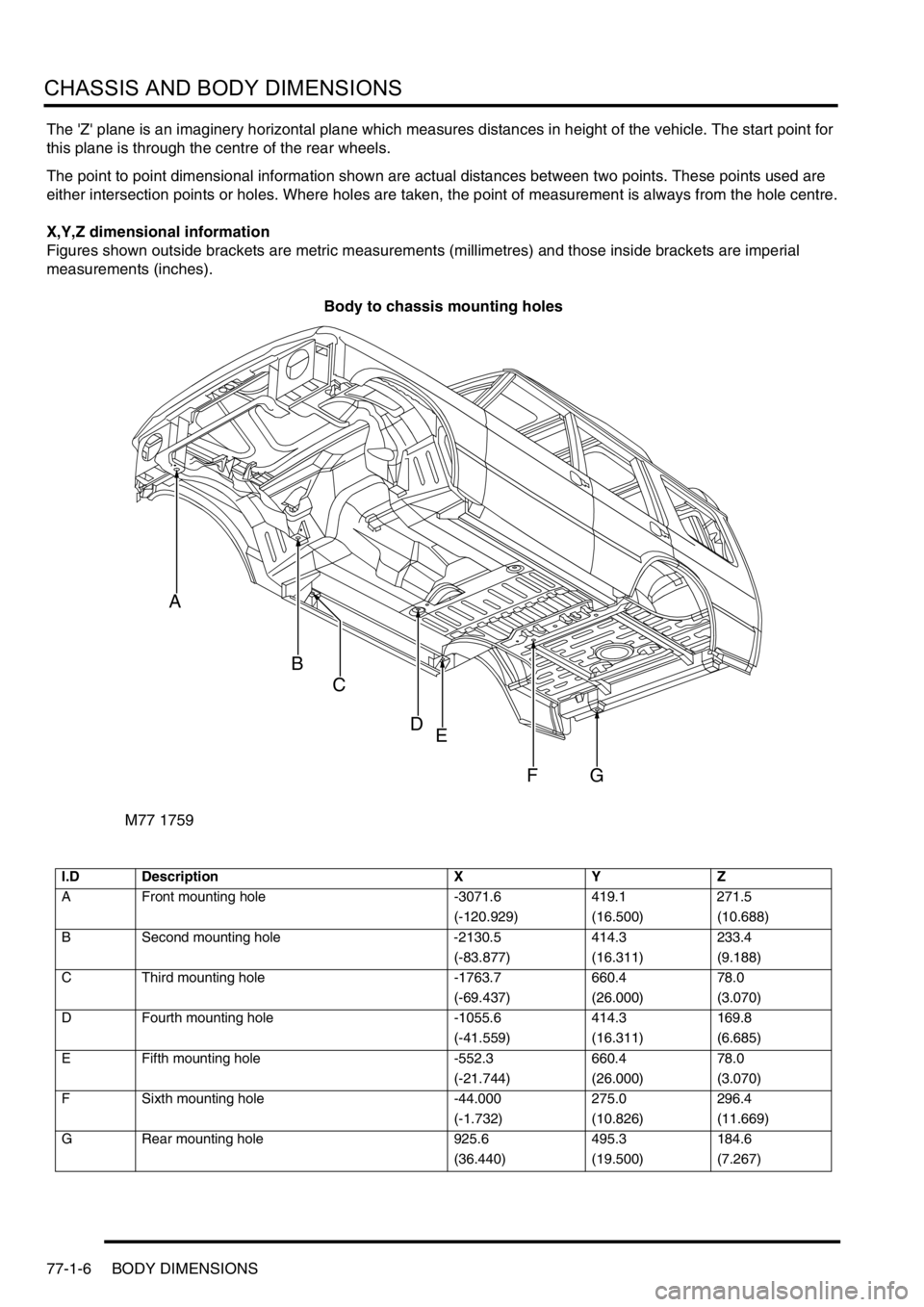
The 'Z' plane is an imaginery horizontal plane which measures distances in height of the vehicle. The start point for
this plane is through the centre of the rear wheels.
The point to point dimensional information shown are actual distances between two points. These points used are
either intersection points or holes. Where holes are taken, the point of measurement is always from the hole centre.
X,Y,Z dimensional information
Figures shown outside brackets are metric measurements (millimetres) and those inside brackets are imperial
measurements (inches).
Body to chassis mounting holes
I.D Description X Y Z
A Front mounting hole -3071.6 419.1 271.5
(-120.929) (16.500) (10.688)
B Second mounting hole -2130.5 414.3 233.4
(-83.877) (16.311) (9.188)
C Third mounting hole -1763.7 660.4 78.0
(-69.437) (26.000) (3.070)
D Fourth mounting hole -1055.6 414.3 169.8
(-41.559) (16.311) (6.685)
E Fifth mounting hole -552.3 660.4 78.0
(-21.744) (26.000) (3.070)
F Sixth mounting hole -44.000 275.0 296.4
(-1.732) (10.826) (11.669)
G Rear mounting hole 925.6 495.3 184.6
(36.440) (19.500) (7.267)
M77 1759
A
B
C
DE
FG
Page 1456 of 1672

LIGHTING
ADJUSTMENTS 86-2-1
LIGHTING ADJUST ME NTS
Headlamps beam alignment - up to 03MY
$% 86.40.17
Check
1.Ensure vehicle is unladen and tyres are at
correct pressures.
2. Models with SLS: Ensure vehicle is at
standard ride height.
3. Models with headlamp levelling: Ensure
headlamp levelling switch is set to '0'.
4.Align suitable beam setting equipment to
headlamp.
5.Switch headlamps on and measure main beam
settings. Beam must be 1.4% below the
horizontal and parallel to the vehicle centre line.
If necessary, adjust headlamp to get correct
beam settings.
6.Align beam setting equipment to 2nd headlamp
and repeat check.
7.Switch off headlamps and remove beam setting
equipment.
Adjust
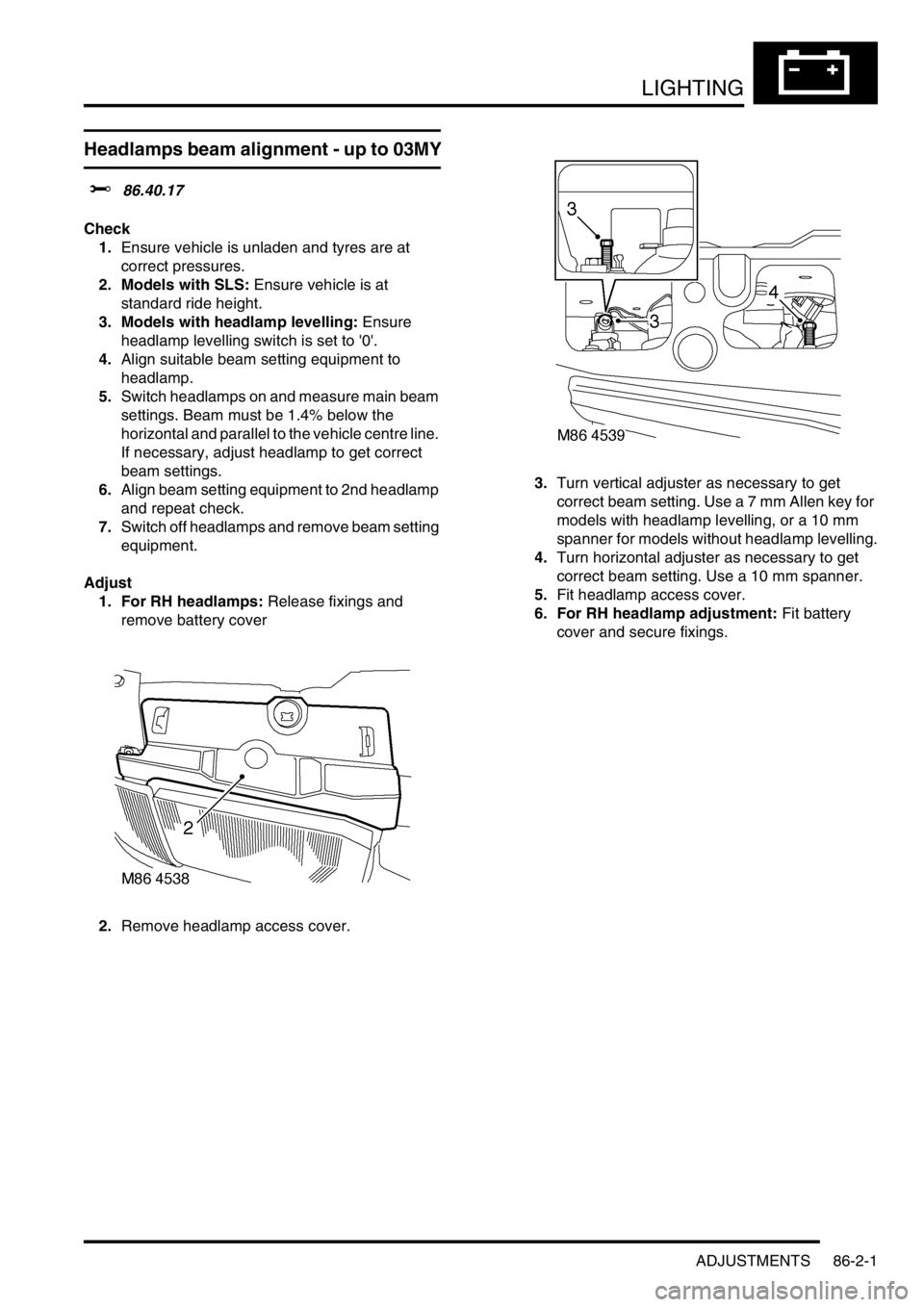
1. For RH headlamps: Release fixings and
remove battery cover
2.Remove headlamp access cover.3.Turn vertical adjuster as necessary to get
correct beam setting. Use a 7 mm Allen key for
models with headlamp levelling, or a 10 mm
spanner for models without headlamp levelling.
4.Turn horizontal adjuster as necessary to get
correct beam setting. Use a 10 mm spanner.
5.Fit headlamp access cover.
6. For RH headlamp adjustment: Fit battery
cover and secure fixings.
Page 1457 of 1672
LIGHTING
86-2-2 ADJUSTMENTS
Headlamps beam alignment - from 03MY
$% 86.40.17
Check
1.Ensure vehicle is unladen and tyres are set at
the correct pressures.
2. Models with SLS: Ensure vehicle is at the
standard ride height.
3. Models without SLS: Set headlamp leveling
switch to zero.
4.Align beam setting equipment to headlamp.
5.Switch on headlamps. Headlamp setting 1.2%
below horizontal and parallel.
6.Align beam setting equipment to second
headlamp and repeat the check.
Adjust
1.Using a flat blade screwdriver rotate the
headlamp adjusters until correct alignment is
achieved
2.Rotate inboard adjuster for verticle alignment.
3.Rotate outboard adjuster for horizontal
alignment.
4.Adjust 2nd headlamp as detailed above.
5.Switch off headlamps and remove beam setting
equipment.
Page 1506 of 1672
BODY CONTROL UNIT
DESCRIPTION AND OPERATION 86-3-37
SLABS raise/lower
Before enabling a SLS vehicle raise/ lower request, the BCU checks the logical condition of the following inputs:
lIgnition state.
lSLABS raise request.
lSLABS lower request.
If the ignition switch is in position 0 or I, the vehicle raise/ lower request is off.
With the ignition switch in position II, and the 'SLABS raise' request and 'SLABS lower' request both off, the vehicle
raise/ lower request output is driven at 25 Hz with a 50% duty cycle and the vehicle height remains unchanged.
If the 'SLABS lower' request input is on, the vehicle raise/lower request output is driven at 25 Hz with a 25% duty cycle,
lowering the vehicle.
If the 'SLABS raise' request input is on, the vehicle raise/lower request output is driven at a 25 Hz with a 75% duty
cycle.
Page 1653 of 1672

INSTRUMENTS
88-26 DESCRIPTION AND OPERATION
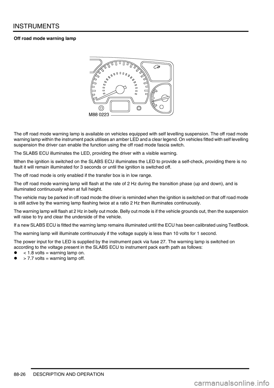
Off road mode warning lamp
The off road mode warning lamp is available on vehicles equipped with self levelling suspension. The off road mode
warning lamp within the instrument pack utilises an amber LED and a clear legend. On vehicles fitted with self levelling
suspension the driver can enable the function using the off road mode fascia switch.
The SLABS ECU illuminates the LED, providing the driver with a visible warning.
When the ignition is switched on the SLABS ECU illuminates the LED to provide a self-check, providing there is no
fault it will remain illuminated for 3 seconds or until the ignition is switched off.
The off road mode is only enabled if the transfer box is in low range.
The off road mode warning lamp will flash at the rate of 2 Hz during the transition phase (up and down), and is
illuminated continuously when at full height.
The vehicle may be parked in off road mode the driver is reminded when the ignition is switched on that off road mode
is still active by the warning lamp flashing twice at a ratio 2 Hz then illuminates continuously.
The warning lamp will flash at 2 Hz in belly out mode. Belly out mode is if the vehicle grounds out, then the suspension
will raise to try and clear the underside of the vehicle.
If a new SLABS ECU is fitted the warning lamp remains illuminated until the ECU has been calibrated using TestBook.
The warning lamp will illuminate continuously if the voltage supply is less than 10 volts for 1 second.
The power input for the LED is supplied by the instrument pack via fuse 27. The warning lamp is switched on
according to the voltage present in the SLABS ECU to instrument pack earth path as follows:
l< 1.8 volts = warning lamp on.
l> 7.7 volts = warning lamp off.
Page 1663 of 1672

INSTRUMENTS
88-36 DESCRIPTION AND OPERATION
Self Levelling Suspension (SLS) warning lamp
The SLS warning lamp within the instrument pack utilises an amber LED and a clear legend. The SLABS ECU
illuminates the LED continuously if a fault within the SLS is detected, providing the driver with a visible warning.
When the ignition is switched on the SLABS ECU illuminates the LED to provide a self-check, providing there is no
fault it will remain illuminated for 3 seconds or until the ignition is switched off.
On vehicles equipped with coil springs the SLS warning lamp is extinguished after 850 milliseconds if the SLABS ECU
configuration of the vehicle is correct.
The SLS warning lamp flashes at 2 Hz when the remote handset control is used to raise or lower the ride height.
If a new SLABS ECU is installed the SLS warning lamp will remain illuminated until the ECU has been calibrated by
TestBook.
The warning lamp will illuminate continuously when battery voltage is less than 10 volts for greater than 1 second.
When the vehicle is in transportation mode the SLS warning lamp is illuminated continuously with ignition on, and will
flash at 2 Hz frequency as the vehicle rises from bump stop level to transport level on engine start.
The power input for the LED is supplied by the instrument pack via fuse 27. The SLABS ECU provides the earth path
to illuminate the warning lamp.
The voltage on the earth path from the SLABS ECU to the instrument pack has the following functions:
l< 1.8 volts = warning lamp on.
l> 7.7 volts = warning lamp off.