2002 LAND ROVER DISCOVERY height
[x] Cancel search: heightPage 1024 of 1672

REAR SUSPENSION
DESCRIPTION AND OPERATION 64-19
Failure modes
Failures are indicated by the SLS warning lamp in the bottom left corner of the instrument pack illuminating
continuously in an amber colour. The following tables show the type of system failures and their effects on the system
operation.
Height sensors
Door Switch Inputs
SLS off-road mode switch
Air supply unit air control valves
Air supply unit compressor
5 Right height sensor earth Input
6 Right height sensor signal Input
C0655
1 Driver's door switch Input
2 Passenger and tail door switches Input
3 Left air valve Output
4 Right air valve Output
5 Exhaust valve Output
6 Air compressor (SLS relay) Output
7 Audible warning Output
8 SLS warning lamp Output
11 ORM switch/ORM warning lamp Input/Output
12 Remote handset raise/lower signal Input
Connectors and pins not listed are either not used or used by the brakes system.
+ BRAKES, DESCRIPTION AND OPERATION, Description.
Failure Effect
Sensor output stuck at 5 V Vehicle will not level
Sensor output stuck at 0 V Vehicle will not level
Mechanical link between radius arm and sensor broken Vehicle will not level
Failure Effect
Harness leads for open doors are are broken or shorted to
V Batt.Air suspension levels when one or more doors are open
Harness leads to door(s) shorted to earth Air suspension will not level
Failure Effect
Fault in wiring harness Off-road mode cannot be selected
Failure of off-road mode switch Off-road mode is activated when switch has not been
selected
Failure Effect
Valves open or short circuit Vehicle does not level or levels unevenly
Failure Effect
Faulty relay, harness fault or compressor fault Vehicle does not level upwards
Page 1025 of 1672
REAR SUSPENSION
64-20 DESCRIPTION AND OPERATION
Operation
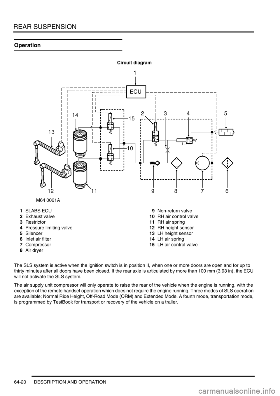
Circuit diagram
1SLABS ECU
2Exhaust valve
3Restrictor
4Pressure limiting valve
5Silencer
6Inlet air filter
7Compressor
8Air dryer9Non-return valve
10RH air control valve
11RH air spring
12RH height sensor
13LH height sensor
14LH air spring
15LH air control valve
The SLS system is active when the ignition switch is in position II, when one or more doors are open and for up to
thirty minutes after all doors have been closed. If the rear axle is articulated by more than 100 mm (3.93 in), the ECU
will not activate the SLS system.
The air supply unit compressor will only operate to raise the rear of the vehicle when the engine is running, with the
exception of the remote handset operation which does not require the engine running. Three modes of SLS operation
are available; Normal Ride Height, Off-Road Mode (ORM) and Extended Mode. A fourth mode, transportation mode,
is programmed by TestBook for transport or recovery of the vehicle on a trailer.
Page 1026 of 1672

REAR SUSPENSION
DESCRIPTION AND OPERATION 64-21
Normal ride height
When the vehicle is stationary, a door is open and the ignition is off, the SLS system will allow the rear of the vehicle
to lower to within 20 mm of the normal ride height as load is removed from the vehicle. The SLS system will only
operate the compressor to raise the rear of the vehicle when the engine is running, unless requested using the remote
handset.
Off-road mode (ORM)
ORM is used to raise the rear of the vehicle from normal ride height to the ORM ride height of 100 mm between the
tip of the bump stop and the axle.
ORM is activated by depressing the ORM switch located on the fascia for not less than 0.5 seconds. With the engine
running, all doors closed and the vehicle speed below 18 mph (30 km/h), the audible warning will sound once and the
ORM warning lamp in the instrument pack will start to flash when the switch is released. The compressor will be
started and the air control valves will be energised by the ECU to inflate the air springs and raise the rear of the vehicle.
When the full ORM height is reached, the ECU will terminate compressor operation and close the air valves. The ORM
warning lamp will stop flashing and remain continuously illuminated to inform the driver that the SLS system is in ORM.
When ORM is no longer required, depressing the ORM switch for not less than 0.5 seconds with all doors closed will
lower the SLS to normal ride height. The audible warning will sound once and the ORM warning lamp will flash as the
suspension lowers. The ECU energises the air control valves and the exhaust valve to release air pressure from the
air springs. When standard ride height is reached the ORM warning lamp will extinguish and the ECU will de-energise
the air control valves and the exhaust valve solenoids.
If the SLS is in ORM and the vehicle speed exceeds 18 mph (30 km/h), the ECU will lower the SLS to standard ride
height. The driver will be informed of this by an audible warning and the ORM warning lamp flashing as the suspension
lowers. When normal ride height is achieved, the ORM warning lamp will extinguish.
At sea level, the time to change the SLS from normal ride height to ORM or visa versa will take between 15 and 20
seconds.
If the ECU determines that conditions are not correct for SLS operation, i.e.; axle articulation or system fault, the
audible warning will sound three times to inform the driver that the ORM request has not been granted.
Extended mode
The extended mode is automatically operated by the ECU and requires no input from the driver. Extended mode
operates when the chassis is grounded causing the rear wheels to spin. This information is generated by the ABS
function of the SLABS ECU.
When the ECU senses that the chassis is grounded and the vehicle speed is less than 6 mph (10 km/h), the ECU will
operate the compressor and energise the air control valves for 25 seconds to raise the rear of the vehicle. This
operates irrespective of the mode that the SLS system is in at that time. To inform the driver, the ORM warning lamp
will flash continuously at all times that the system is in extended mode.
The driver can exit the extended mode by depressing the ORM switch for not less than 0.5 seconds or by exceeding
8 mph (13 km/h).
Remote handset SLS control
The remote handset is an accessory item which allows the SLS to be operated between normal ride height and bump
stop height to allow easier connection and disconnection of trailers. The remote handset is similar in appearance to
that of the remote door locking handset but does not have an integral key. A circular button with an arrow is used to
raise the SLS and an oval button with the 'Land Rover' logo is used to lower the SLS.
The remote handset control requires all doors to be closed and the ignition to be in position II, but the engine does
not need to be running.
Page 1027 of 1672

REAR SUSPENSION
64-22 DESCRIPTION AND OPERATION
Pressing the lower button will signal the SLABS ECU, via the RF receiver and the BCU, to energise the exhaust valve
and air control valves. The SLS will lower up to 60 mm (2.36 in) below normal ride height if the button is held. If the
button is released the SLS will stop at that point.
Pressing the raise button will signal the SLABS ECU, via the RF receiver and the BCU, to start the compressor and
energise the exhaust valve and air control valves. The SLS will raise to normal ride height if the button is held. If the
button is released the SLS will stop at that point.
When raising or lowering the SLS using the remote handset, the SLS warning lamp will flash and the audible warning
will sound when the system is operating. When the SLS is fully lowered the warning lamp will stay illuminated. The
SLS will reset to normal ride height if the vehicle speed exceeds 3 mph (5 km/h) for 10 seconds when the SLS is
lowered.
Transportation mode
Transportation mode must be used when the vehicle is transported on a trailer and secured by the chassis. The
transportation mode can only be enabled and disabled with TestBook.
The transportation mode lowers the rear suspension onto the bump stops with the engine not running. When the
suspension is in transportation mode, the SLS warning lamp is continuously illuminated when the ignition is in position
II.
When the engine is started in transportation mode, the SLS system will raise the rear suspension until a gap of 25
mm (1 in.) exists between the bump stop and the axle. The SLS warning lamp will flash continuously while the SLS
system is raising the suspension. When the gap between the bump stop and the axle is achieved, the warning lamp
will illuminate continuously.
When TestBook is used to disable the transportation mode, the rear suspension will raise to normal ride height when
the engine is running.
Page 1034 of 1672
REAR SUSPENSION
REPAIRS 64-29
Damper - rear
$% 64.30.02
Remove
1.Raise rear of vehicle and support under
chassis.
WARNING: Do not work on or under a
vehicle supported only by a jack. Always
support the vehicle on safety stands.
2.Remove road wheel.
3.Support weight of axle on a jack.
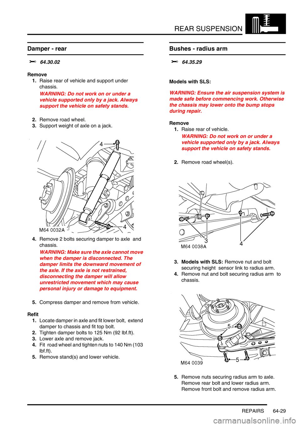
4.Remove 2 bolts securing damper to axle and
chassis.
WARNING: Make sure the axle cannot move
when the damper is disconnected. The
damper limits the downward movement of
the axle. If the axle is not restrained,
disconnecting the damper will allow
unrestricted movement which may cause
personal injury or damage to equipment.
5.Compress damper and remove from vehicle.
Refit
1.Locate damper in axle and fit lower bolt, extend
damper to chassis and fit top bolt.
2.Tighten damper bolts to 125 Nm (92 lbf.ft).
3.Lower axle and remove jack.
4.Fit road wheel and tighten nuts to 140 Nm (103
lbf.ft).
5.Remove stand(s) and lower vehicle.
Bushes - radius arm
$% 64.35.29
Models with SLS:
WARNING: Ensure the air suspension system is
made safe before commencing work. Otherwise
the chassis may lower onto the bump stops
during repair.
Remove
1.Raise rear of vehicle.
WARNING: Do not work on or under a
vehicle supported only by a jack. Always
support the vehicle on safety stands.
2.Remove road wheel(s).
3. Models with SLS: Remove nut and bolt
securing height sensor link to radius arm.
4.Remove nut and bolt securing radius arm to
chassis.
5.Remove nuts securing radius arm to axle.
Remove rear bolt and lower radius arm.
Remove front bolt and remove radius arm.
Page 1035 of 1672
REAR SUSPENSION
64-30 REPAIRS
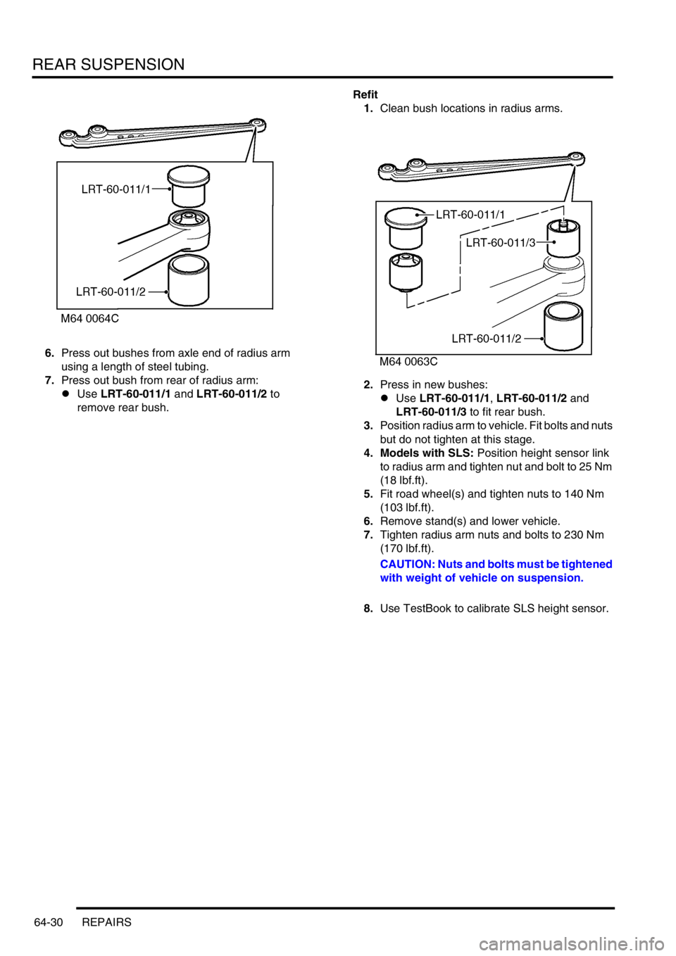
6.Press out bushes from axle end of radius arm
using a length of steel tubing.
7.Press out bush from rear of radius arm:
lUse LRT-60-011/1 and LRT-60-011/2 to
remove rear bush.Refit
1.Clean bush locations in radius arms.
2.Press in new bushes:
lUse LRT-60-011/1, LRT-60-011/2 and
LRT-60-011/3 to fit rear bush.
3.Position radius arm to vehicle. Fit bolts and nuts
but do not tighten at this stage.
4. Models with SLS: Position height sensor link
to radius arm and tighten nut and bolt to 25 Nm
(18 lbf.ft).
5.Fit road wheel(s) and tighten nuts to 140 Nm
(103 lbf.ft).
6.Remove stand(s) and lower vehicle.
7.Tighten radius arm nuts and bolts to 230 Nm
(170 lbf.ft).
CAUTION: Nuts and bolts must be tightened
with weight of vehicle on suspension.
8.Use TestBook to calibrate SLS height sensor.
Page 1037 of 1672
REAR SUSPENSION
64-32 REPAIRS
Sensor - height - SLS
$% 64.36.01
WARNING: Ensure the air suspension system is
made safe before commencing work. Otherwise
the chassis may lower onto the bump stops
during repair.
Remove
1.Raise rear of vehicle.
WARNING: Do not work on or under a
vehicle supported only by a jack. Always
support the vehicle on safety stands.
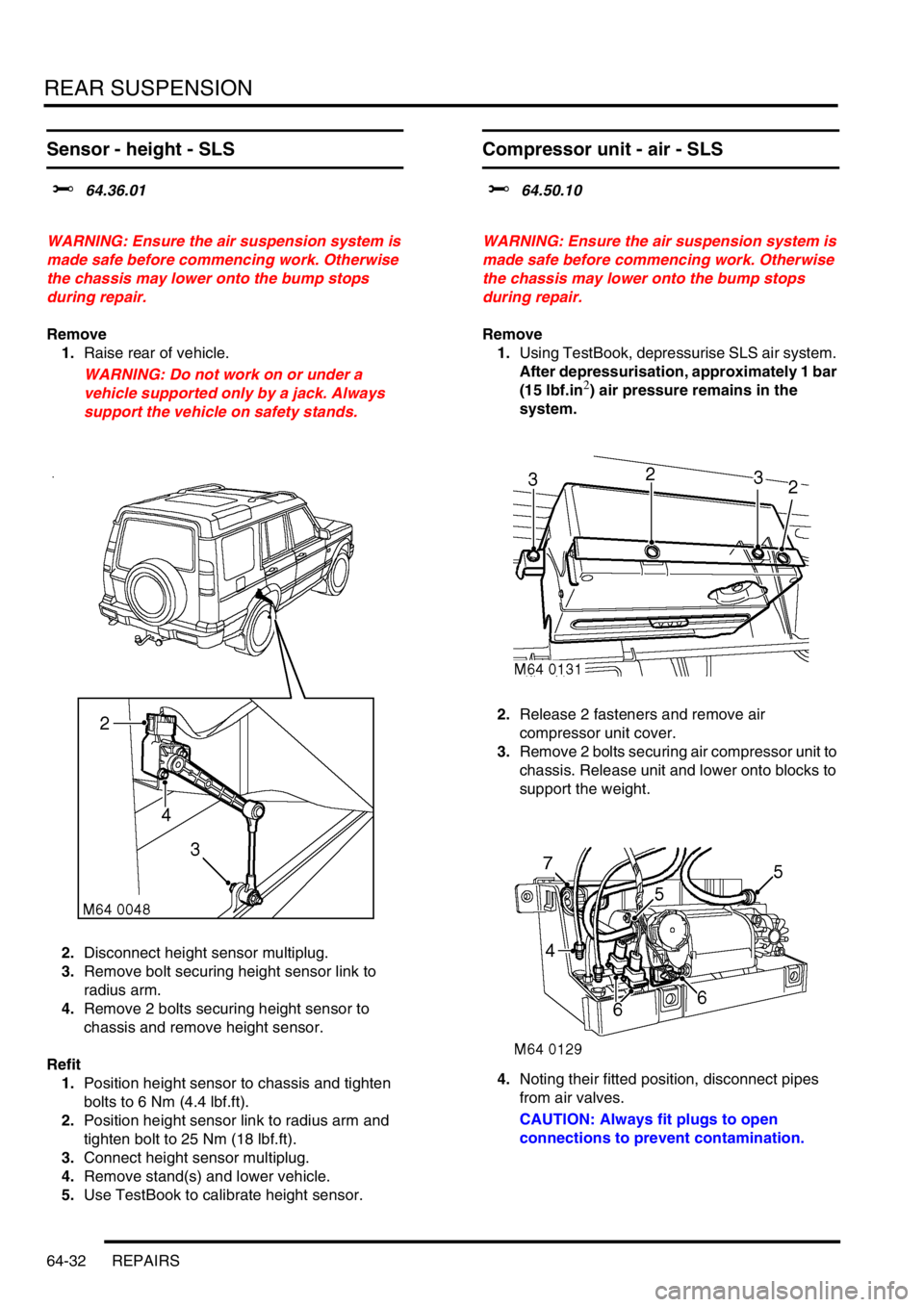
2.Disconnect height sensor multiplug.
3.Remove bolt securing height sensor link to
radius arm.
4.Remove 2 bolts securing height sensor to
chassis and remove height sensor.
Refit
1.Position height sensor to chassis and tighten
bolts to 6 Nm (4.4 lbf.ft).
2.Position height sensor link to radius arm and
tighten bolt to 25 Nm (18 lbf.ft).
3.Connect height sensor multiplug.
4.Remove stand(s) and lower vehicle.
5.Use TestBook to calibrate height sensor.
Compressor unit - air - SLS
$% 64.50.10
WARNING: Ensure the air suspension system is
made safe before commencing work. Otherwise
the chassis may lower onto the bump stops
during repair.
Remove
1.Using TestBook, depressurise SLS air system.
After depressurisation, approximately 1 bar
(15 lbf.in
2) air pressure remains in the
system.
2.Release 2 fasteners and remove air
compressor unit cover.
3.Remove 2 bolts securing air compressor unit to
chassis. Release unit and lower onto blocks to
support the weight.
4.Noting their fitted position, disconnect pipes
from air valves.
CAUTION: Always fit plugs to open
connections to prevent contamination.
Page 1039 of 1672
REAR SUSPENSION
64-34 REPAIRS
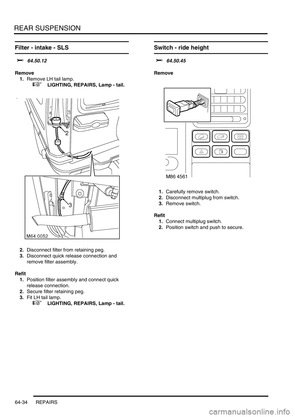
Filter - intake - SLS
$% 64.50.12
Remove
1.Remove LH tail lamp.
+ LIGHTING, REPAIRS, Lamp - tail.
2.Disconnect filter from retaining peg.
3.Disconnect quick release connection and
remove filter assembly.
Refit
1.Position filter assembly and connect quick
release connection.
2.Secure filter retaining peg.
3.Fit LH tail lamp.
+ LIGHTING, REPAIRS, Lamp - tail.
Switch - ride height
$% 64.50.45
Remove
1.Carefully remove switch.
2.Disconnect multiplug from switch.
3.Remove switch.
Refit
1.Connect multiplug switch.
2.Position switch and push to secure.