Page 1072 of 1672
BRAKES
DESCRIPTION AND OPERATION 70-27
Drum brake
1Drum
2Drum securing bolt
3Backplate
4Cable
5Backplate securing bolt
The drum brake consists of a backplate attached to the transfer box casing and a drum attached to the transfer box
rear output shaft. When the handbrake lever is applied, the movement is transmitted by the inner cable to a lever on
one of the brake shoes on the backplate. The lever pivots against the brake adjuster rod, which forces the shoes apart
and into contact with the drum. Brake shoe to drum clearance is set by an adjusting bolt on the rear of the backplate.
Page 1074 of 1672
BRAKES
ADJUSTMENTS 70-29
ADJUST ME NTS
Handbrake
$% 70.45.09
Check
1.Apply the handbrake lever 3 notches on the
ratchet. The handbrake should be fully
operational.
2.If the handbrake is not fully operational, the
brake shoes and/or the handbrake cable need
adjusting.
Adjust
1.Raise rear of vehicle.
WARNING: Do not work on or under a
vehicle supported only by a jack. Always
support the vehicle on safety stands.
2.Ensure handbrake lever is fully released.
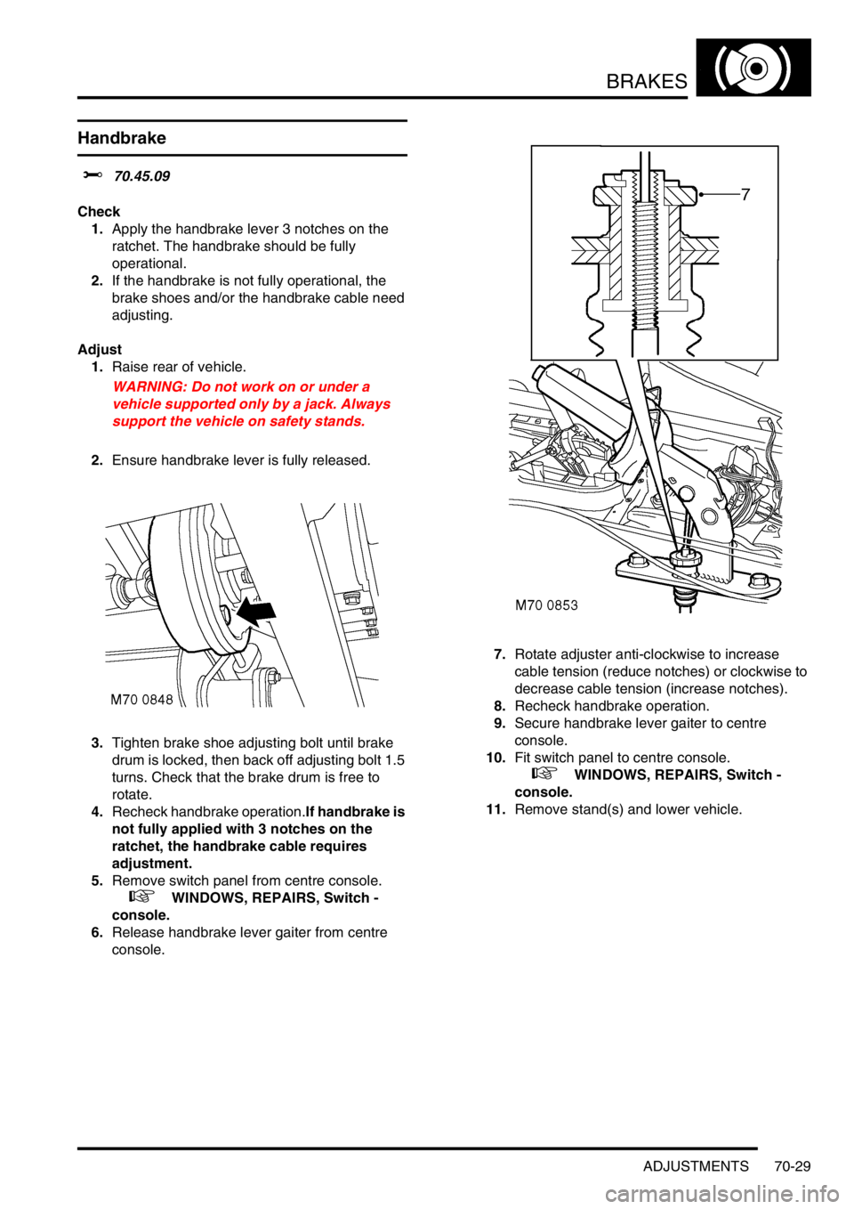
3.Tighten brake shoe adjusting bolt until brake
drum is locked, then back off adjusting bolt 1.5
turns. Check that the brake drum is free to
rotate.
4.Recheck handbrake operation.If handbrake is
not fully applied with 3 notches on the
ratchet, the handbrake cable requires
adjustment.
5.Remove switch panel from centre console.
+ WINDOWS, REPAIRS, Switch -
console.
6.Release handbrake lever gaiter from centre
console.7.Rotate adjuster anti-clockwise to increase
cable tension (reduce notches) or clockwise to
decrease cable tension (increase notches).
8.Recheck handbrake operation.
9.Secure handbrake lever gaiter to centre
console.
10.Fit switch panel to centre console.
+ WINDOWS, REPAIRS, Switch -
console.
11.Remove stand(s) and lower vehicle.
Page 1081 of 1672
BRAKES
70-36 REPAIRS
Cable - handbrake
$% 70.35.25
Remove
1.Remove centre console.
+ INTERIOR TRIM COMPONENTS,
REPAIRS, Console - centre - automatic
models.
+ INTERIOR TRIM COMPONENTS,
REPAIRS, Console - centre - manual
models.
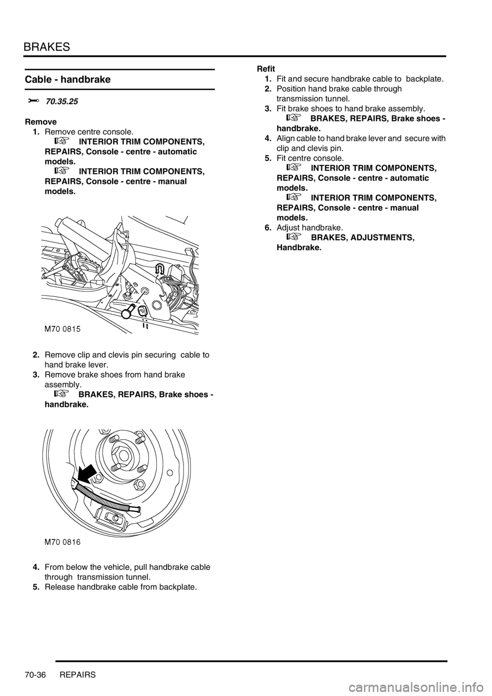
2.Remove clip and clevis pin securing cable to
hand brake lever.
3.Remove brake shoes from hand brake
assembly.
+ BRAKES, REPAIRS, Brake shoes -
handbrake.
4.From below the vehicle, pull handbrake cable
through transmission tunnel.
5.Release handbrake cable from backplate. Refit
1.Fit and secure handbrake cable to backplate.
2.Position hand brake cable through
transmission tunnel.
3.Fit brake shoes to hand brake assembly.
+ BRAKES, REPAIRS, Brake shoes -
handbrake.
4.Align cable to hand brake lever and secure with
clip and clevis pin.
5.Fit centre console.
+ INTERIOR TRIM COMPONENTS,
REPAIRS, Console - centre - automatic
models.
+ INTERIOR TRIM COMPONENTS,
REPAIRS, Console - centre - manual
models.
6.Adjust handbrake.
+ BRAKES, ADJUSTMENTS,
Handbrake.
Page 1084 of 1672
BRAKES
REPAIRS 70-39
4.Using tool LRT-70-500, press caliper pistons
fully into bores. Ensure that displaced fluid
does not overflow from reservoir.
5.Fit pads to caliper carrier.
6.Lower caliper housing over pads.
7.Ensure flats on guide pins locate with lugs on
caliper housing. fit new pivot bolt and tighten to
30 Nm (22 lbf.ft).
8.Fit road wheel(s) and tighten nuts to 140 Nm
(103 lbf.ft).
9.Remove stand(s) and lower vehicle.
10.Depress brake several times to set pad to disc
clearance.
11.Check and top-up brake fluid.
Brake shoes - handbrake
$% 70.45.18
Remove
1.Remove rear propeller shaft.
+ PROPELLER SHAFTS, REPAIRS,
Propeller shaft - rear.
2.Remove screw and remove brake drum.
Page 1085 of 1672
BRAKES
70-40 REPAIRS
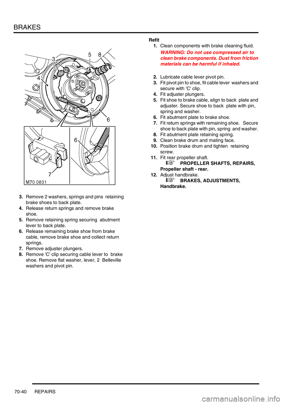
3.Remove 2 washers, springs and pins retaining
brake shoes to back plate.
4.Release return springs and remove brake
shoe.
5.Remove retaining spring securing abutment
lever to back plate.
6.Release remaining brake shoe from brake
cable, remove brake shoe and collect return
springs.
7.Remove adjuster plungers.
8.Remove 'C' clip securing cable lever to brake
shoe. Remove flat washer, lever, 2 Belleville
washers and pivot pin. Refit
1.Clean components with brake cleaning fluid.
WARNING: Do not use compressed air to
clean brake components. Dust from friction
materials can be harmful if inhaled.
2.Lubricate cable lever pivot pin.
3.Fit pivot pin to shoe, fit cable lever washers and
secure with 'C' clip.
4.Fit adjuster plungers.
5.Fit shoe to brake cable, align to back plate and
adjuster. Secure shoe to back plate with pin,
spring and washer.
6.Fit abutment plate to brake shoe.
7.Fit return springs with remaining shoe. Secure
shoe to back plate with pin, spring and washer.
8.Fit abutment plate retaining spring.
9.Clean brake drum and mating face.
10.Position brake drum and tighten retaining
screw.
11.Fit rear propeller shaft.
+ PROPELLER SHAFTS, REPAIRS,
Propeller shaft - rear.
12.Adjust handbrake.
+ BRAKES, ADJUSTMENTS,
Handbrake.
Page 1094 of 1672
BRAKES
REPAIRS 70-49
Switch - handbrake
$% 86.65.45
Remove
1.Remove centre console.
+ INTERIOR TRIM COMPONENTS,
REPAIRS, Console - centre - automatic
models.
+ INTERIOR TRIM COMPONENTS,
REPAIRS, Console - centre - manual
models.
2.Disconnect Lucar from handbrake warning
switch.
3.Remove clip and clevis pin securing cable to
handbrake lever.
4.Remove 2 bolts and remove handbrake lever.
5.Remove 2 screws securing switch to
handbrake lever and remove switch.
Refit
1.Fit switch to handbrake lever and tighten
screws.
2.Position handbrake lever to floor and tighten
bolts to 22 Nm (16 lbf.ft).
3.Align cable to handbrake lever and fit clevis pin
and clip.
4.Connect Lucar to handbrake switch.
5.Fit centre console.
+ INTERIOR TRIM COMPONENTS,
REPAIRS, Console - centre - automatic
models.
+ INTERIOR TRIM COMPONENTS,
REPAIRS, Console - centre - manual
models.
Page 1103 of 1672
RESTRAINT SYSTEMS
75-8 DESCRIPTION AND OPERATION
Diagnostic and Control Unit (DCU)
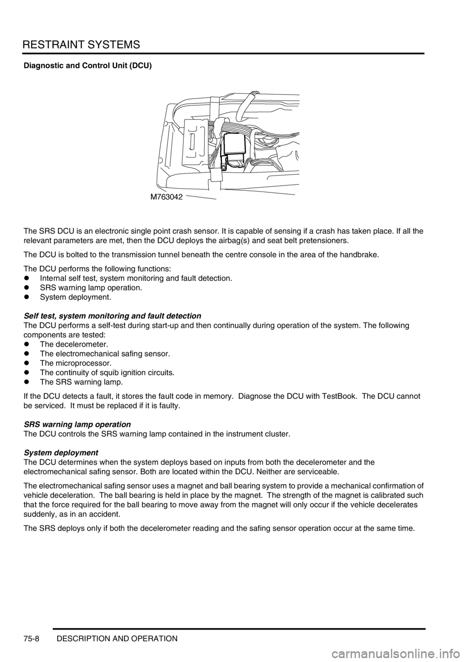
The SRS DCU is an electronic single point crash sensor. It is capable of sensing if a crash has taken place. If all the
relevant parameters are met, then the DCU deploys the airbag(s) and seat belt pretensioners.
The DCU is bolted to the transmission tunnel beneath the centre console in the area of the handbrake.
The DCU performs the following functions:
lInternal self test, system monitoring and fault detection.
lSRS warning lamp operation.
lSystem deployment.
Self test, system monitoring and fault detection
The DCU performs a self-test during start-up and then continually during operation of the system. The following
components are tested:
lThe decelerometer.
lThe electromechanical safing sensor.
lThe microprocessor.
lThe continuity of squib ignition circuits.
lThe SRS warning lamp.
If the DCU detects a fault, it stores the fault code in memory. Diagnose the DCU with TestBook. The DCU cannot
be serviced. It must be replaced if it is faulty.
SRS warning lamp operation
The DCU controls the SRS warning lamp contained in the instrument cluster.
System deployment
The DCU determines when the system deploys based on inputs from both the decelerometer and the
electromechanical safing sensor. Both are located within the DCU. Neither are serviceable.
The electromechanical safing sensor uses a magnet and ball bearing system to provide a mechanical confirmation of
vehicle deceleration. The ball bearing is held in place by the magnet. The strength of the magnet is calibrated such
that the force required for the ball bearing to move away from the magnet will only occur if the vehicle decelerates
suddenly, as in an accident.
The SRS deploys only if both the decelerometer reading and the safing sensor operation occur at the same time.
Page 1104 of 1672
RESTRAINT SYSTEMS
DESCRIPTION AND OPERATION 75-9
Operation - SRS
The diagnostic and control unit (DCU) controls the SRS system. The DCU is located beneath the centre console close
to the handbrake area. The DCU contains both an electronic deceleration sensor as well as an electromechanical
safing sensor. When the electronic deceleration sensor within the DCU detects rapid deceleration of the vehicle, it
compares the deceleration rate with stored values in its' memory. If the deceleration rate exceeds the stored value
and the electromechanical safing sensor triggers, the DCU deploys the airbag and the seat belt pretensioners. The
DCU will not deploy the airbags and seat belt pretensioners unless both sensors trigger.
The SRS has diagnostic capabilities through TestBook. In the event that a fault is detected, the DCU alerts the driver
by illuminating a warning lamp in the instrument cluster.
The DCU controls the following:
lSRS warning lamp.
lDrivers airbag module.
lPassenger airbag module (where fitted).
lDriver seat belt pretensioner.
lPassenger seat belt pretensioner.
WARNING: The integrity of the SRS system are critical for safety reasons. Ensure the following precautions
are always adhered to:
lNever install used SRS components from another vehicle or attempt to repair an SRS component.
lWhen repairing an SRS system only use genuine new parts.
lNever apply electrical power to an SRS component unless instructed to do so as part of an approved test
procedure.
lSpecial Torx bolts are necessary for installing the airbag module - do not use other bolts. Ensure bolts
are tightened to the correct torque.
lAlways use new fixings when replacing an SRS component.
lEnsure the SRS Diagnostic Control Unit (DCU) is always installed correctly. There must not be any gap
between the DCU and the bracket to which it is mounted. An incorrectly mounted DCU could cause the
system to malfunction.
System deployment
The airbag and seat belt pretensioners deploy to protect the front seat occupants when the DCU senses a rapid
vehicle deceleration. The system deploys when the following conditions are met:
lThe ignition switch is on.
lThe vehicle decelerates beyond a threshold defined within the DCU.
lThe electromechanical safing sensor within the DCU triggers.
When all of the above conditions are met, the DCU deploys the airbag(s) and seat belt pretensioners. If the above
conditions are not met, the DCU will not deploy the system.
Component replacement policy
After an impact which deploys the airbags and pretensioners, the following components must be renewed:
lDCU.
lDriver and passenger airbag modules.
lDriver and passenger buckle pretensioners.
lRotary coupler.
lFlyleads (where applicable) connecting airbags and pre-tensioners to SRS harness