Page 1121 of 1672
RESTRAINT SYSTEMS
75-26 REPAIRS
6.Ensure airbag module mounting brackets are
secure.
7.Connect flylead SMD 4082/5 to airbag module.
WARNING: Ensure the deployment tool is
not connected to the battery.
8.Connect flylead SMD 4082/5 to tool SMD 4082/
1.
9.Connect tool SMD 4082/1 to battery.
WARNING: Ensure all personnel are at least
15 metres (50 ft) away from the airbag
module.10.Press both operating buttons to deploy airbag
module.
11.DO NOT return to airbag module for 30
minutes.
12.Using gloves and face mask, remove airbag
module from tool, place airbag module in
plastic bag and seal bag.
13.Wipe down tool with damp cloth.
14.Transport deployed airbag module to
designated area for incineration.
NOTE: DO NOT re-use or salvage any parts of
the airbag system.Do not transport deployed
SRS components in the vehicle passenger
compartment.
Page 1122 of 1672
RESTRAINT SYSTEMS
REPAIRS 75-27
Pre-tensioner - deployment
$% 76.74.99
These guidelines are written to aid authorised
personnel to carry out the safe disposal of pre-
tensioners.
If a vehicle is to be scrapped and contains an
undeployed pre-tensioner, the pre-tensioner
must be manually deployed. This operation
should only be carried out using the following
recommended manual deployment procedure.
Before deployment is started the deployment
tool self test procedure should be carried out.
WARNING: Only use approved deployment
equipment, and only deploy SRS components in
a well ventilated designated area. Ensure SRS
components are not damaged or ruptured before
deployment. Notify the relevant authorities.
Deploy
1.Carry out deployment tool self test.
+ RESTRAINT SYSTEMS, REPAIRS,
Airbag deployment tool - self test.
2.Slide seat fully rearwards to access pre-
tensioner harness connector.
3.Disconnect pre-tensioner harness connector.
Ensure deployment tool SMD 4082/1 is not
connected to battery.
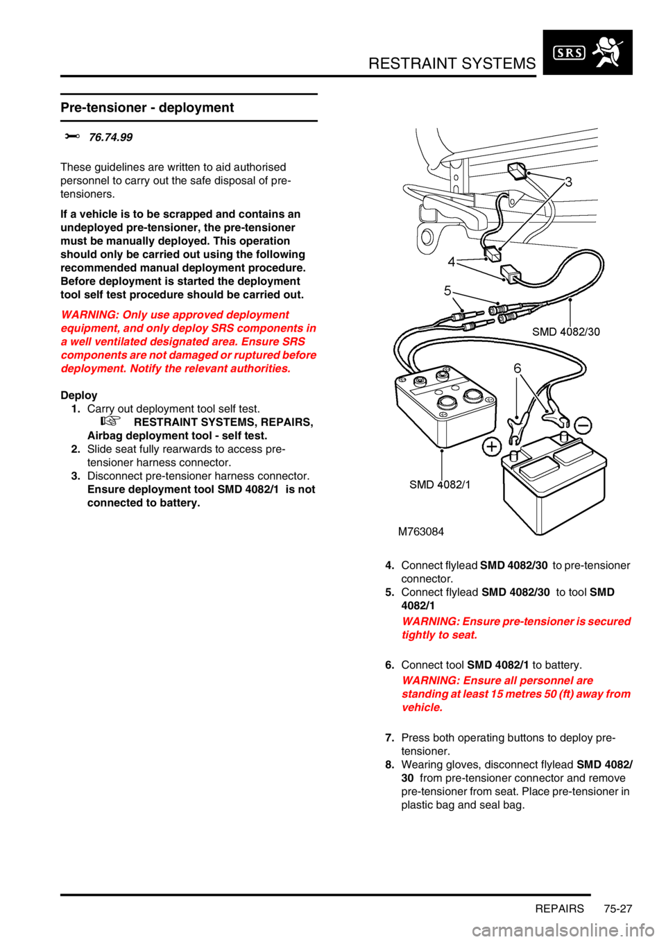
4.Connect flylead SMD 4082/30 to pre-tensioner
connector.
5.Connect flylead SMD 4082/30 to tool SMD
4082/1
WARNING: Ensure pre-tensioner is secured
tightly to seat.
6.Connect tool SMD 4082/1 to battery.
WARNING: Ensure all personnel are
standing at least 15 metres 50 (ft) away from
vehicle.
7.Press both operating buttons to deploy pre-
tensioner.
8.Wearing gloves, disconnect flylead SMD 4082/
30 from pre-tensioner connector and remove
pre-tensioner from seat. Place pre-tensioner in
plastic bag and seal bag.
Page 1162 of 1672
INTERIOR TRIM COMPONENTS
REPAIRS 76-3-9
16.Remove console.
NOTE: Do not carry out further dismantling if
component is removed for access only.
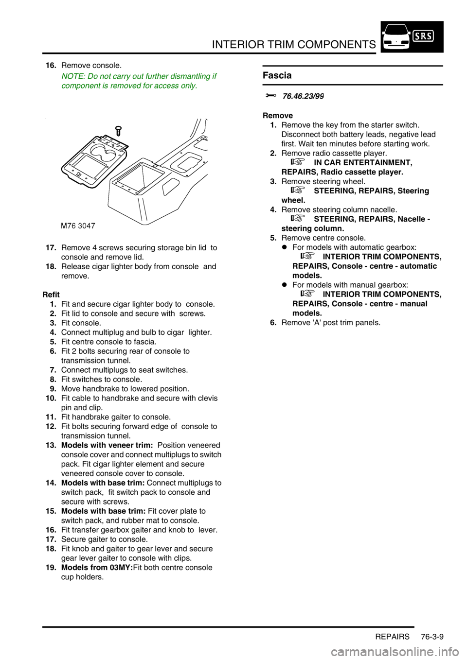
17.Remove 4 screws securing storage bin lid to
console and remove lid.
18.Release cigar lighter body from console and
remove.
Refit
1.Fit and secure cigar lighter body to console.
2.Fit lid to console and secure with screws.
3.Fit console.
4.Connect multiplug and bulb to cigar lighter.
5.Fit centre console to fascia.
6.Fit 2 bolts securing rear of console to
transmission tunnel.
7.Connect multiplugs to seat switches.
8.Fit switches to console.
9.Move handbrake to lowered position.
10.Fit cable to handbrake and secure with clevis
pin and clip.
11.Fit handbrake gaiter to console.
12.Fit bolts securing forward edge of console to
transmission tunnel.
13. Models with veneer trim: Position veneered
console cover and connect multiplugs to switch
pack. Fit cigar lighter element and secure
veneered console cover to console.
14. Models with base trim: Connect multiplugs to
switch pack, fit switch pack to console and
secure with screws.
15. Models with base trim: Fit cover plate to
switch pack, and rubber mat to console.
16.Fit transfer gearbox gaiter and knob to lever.
17.Secure gaiter to console.
18.Fit knob and gaiter to gear lever and secure
gear lever gaiter to console with clips.
19. Models from 03MY:Fit both centre console
cup holders.
Fascia
$% 76.46.23/99
Remove
1.Remove the key from the starter switch.
Disconnect both battery leads, negative lead
first. Wait ten minutes before starting work.
2.Remove radio cassette player.
+ IN CAR ENTERTAINMENT,
REPAIRS, Radio cassette player.
3.Remove steering wheel.
+ STEERING, REPAIRS, Steering
wheel.
4.Remove steering column nacelle.
+ STEERING, REPAIRS, Nacelle -
steering column.
5.Remove centre console.
lFor models with automatic gearbox:
+ INTERIOR TRIM COMPONENTS,
REPAIRS, Console - centre - automatic
models.
lFor models with manual gearbox:
+ INTERIOR TRIM COMPONENTS,
REPAIRS, Console - centre - manual
models.
6.Remove 'A' post trim panels.
Page 1165 of 1672
INTERIOR TRIM COMPONENTS
76-3-12 REPAIRS
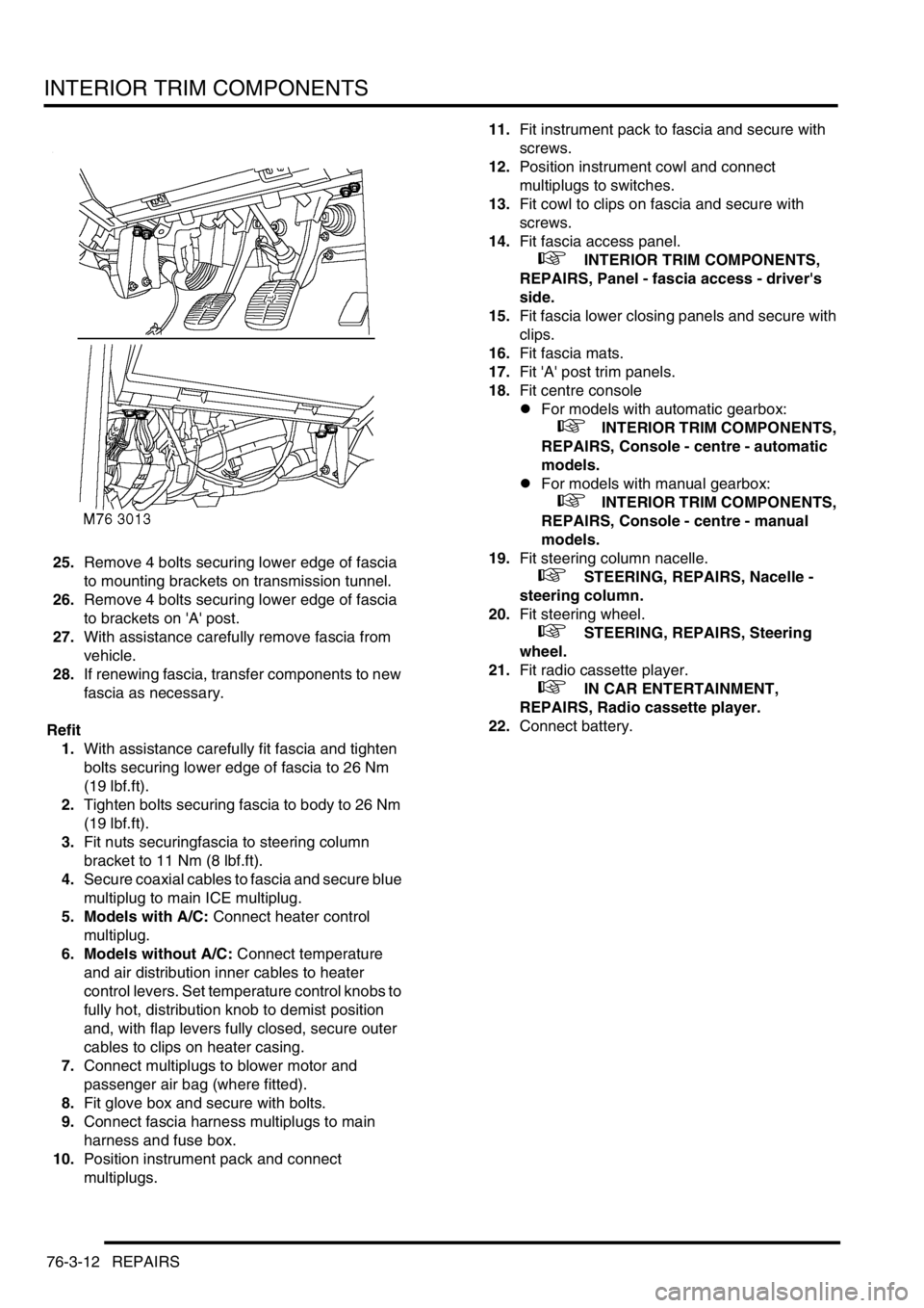
25.Remove 4 bolts securing lower edge of fascia
to mounting brackets on transmission tunnel.
26.Remove 4 bolts securing lower edge of fascia
to brackets on 'A' post.
27.With assistance carefully remove fascia from
vehicle.
28.If renewing fascia, transfer components to new
fascia as necessary.
Refit
1.With assistance carefully fit fascia and tighten
bolts securing lower edge of fascia to 26 Nm
(19 lbf.ft).
2.Tighten bolts securing fascia to body to 26 Nm
(19 lbf.ft).
3.Fit nuts securingfascia to steering column
bracket to 11 Nm (8 lbf.ft).
4.Secure coaxial cables to fascia and secure blue
multiplug to main ICE multiplug.
5. Models with A/C: Connect heater control
multiplug.
6. Models without A/C: Connect temperature
and air distribution inner cables to heater
control levers. Set temperature control knobs to
fully hot, distribution knob to demist position
and, with flap levers fully closed, secure outer
cables to clips on heater casing.
7.Connect multiplugs to blower motor and
passenger air bag (where fitted).
8.Fit glove box and secure with bolts.
9.Connect fascia harness multiplugs to main
harness and fuse box.
10.Position instrument pack and connect
multiplugs.11.Fit instrument pack to fascia and secure with
screws.
12.Position instrument cowl and connect
multiplugs to switches.
13.Fit cowl to clips on fascia and secure with
screws.
14.Fit fascia access panel.
+ INTERIOR TRIM COMPONENTS,
REPAIRS, Panel - fascia access - driver's
side.
15.Fit fascia lower closing panels and secure with
clips.
16.Fit fascia mats.
17.Fit 'A' post trim panels.
18.Fit centre console
lFor models with automatic gearbox:
+ INTERIOR TRIM COMPONENTS,
REPAIRS, Console - centre - automatic
models.
lFor models with manual gearbox:
+ INTERIOR TRIM COMPONENTS,
REPAIRS, Console - centre - manual
models.
19.Fit steering column nacelle.
+ STEERING, REPAIRS, Nacelle -
steering column.
20.Fit steering wheel.
+ STEERING, REPAIRS, Steering
wheel.
21.Fit radio cassette player.
+ IN CAR ENTERTAINMENT,
REPAIRS, Radio cassette player.
22.Connect battery.
Page 1189 of 1672
SEATS
76-5-4 DESCRIPTION AND OPERATION
Description - electric seats
General
All markets use the same electric seat system. Electically operated lumbar support is optional. The system consists
of an electrical sub-system and a mechanical sub-system.
The electrical sub-system consists of the following components:
lBCU.
lSeat power relays.
lSeat switch packs.
lSeat fore/ aft motors.
lSeat cushion front up/ down motors.
lSeat cushion rear up/ down motors.
lSeat squab motor.
lLumbar pump.
lLumbar deflate solenoid.
The mechanical sub-system consist of the following components:
lGear wheels.
lRack and pinion assemblies.
Seat power relay
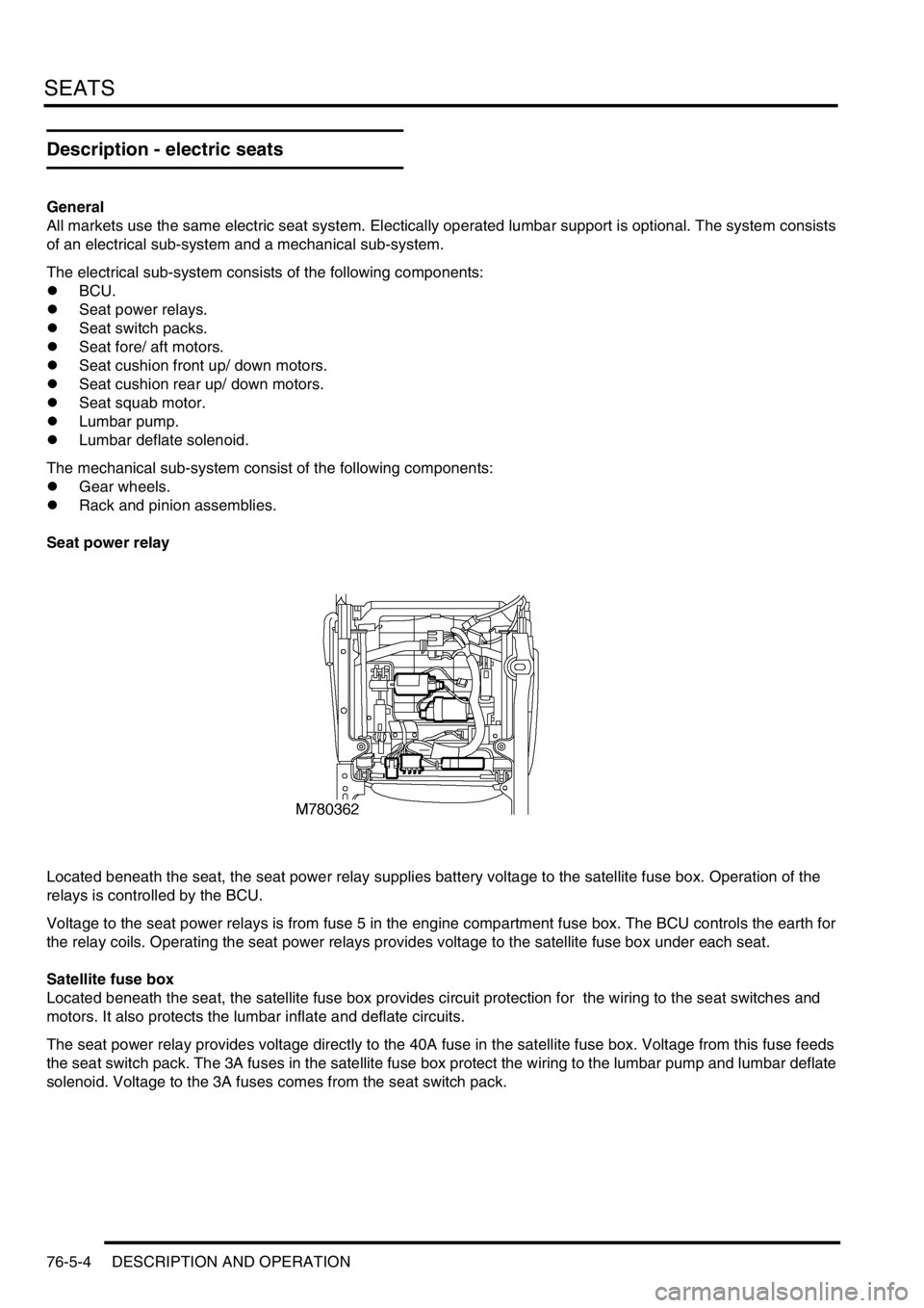
Located beneath the seat, the seat power relay supplies battery voltage to the satellite fuse box. Operation of the
relays is controlled by the BCU.
Voltage to the seat power relays is from fuse 5 in the engine compartment fuse box. The BCU controls the earth for
the relay coils. Operating the seat power relays provides voltage to the satellite fuse box under each seat.
Satellite fuse box
Located beneath the seat, the satellite fuse box provides circuit protection for the wiring to the seat switches and
motors. It also protects the lumbar inflate and deflate circuits.
The seat power relay provides voltage directly to the 40A fuse in the satellite fuse box. Voltage from this fuse feeds
the seat switch pack. The 3A fuses in the satellite fuse box protect the wiring to the lumbar pump and lumbar deflate
solenoid. Voltage to the 3A fuses comes from the seat switch pack.
Page 1200 of 1672
SEATS
REPAIRS 76-5-15
REPAIRS
Seat - front
$% 78.10.43.99
Remove
1.Disconnect battery earth lead.
2.Remove 3 screws and 1 trim clip securing
lower trim casing to seat.
3.Remove lower trim casing.
4.Remove cap from front seat belt lower
anchorage bolt.
5.Remove front seat belt lower anchorage bolt. 6.Remove 4 Torx bolts and nut securing front
seat to floor.
7.Lean seat forward to gain access to multiplugs.
Page 1201 of 1672
SEATS
76-5-16 REPAIRS
8.Release pretensioner multiplug from seat
frame and disconnect.
9. Electrically operated seats: Disconnect 2
seat motor multiplugs.
10.Remove front seat.
Refit
1.Fit front seat in vehicle.
2. Electrically operated seats: Connect seat
motor multiplugs.
3.Connect pretensioner multiplug and secure to
seat frame.
4.Fit Torx bolts and nut securing front seat to floor
and tighten to 45 Nm (33 lbf.ft).
5.Fit front seat belt lower anchorage bolt to front
seat and tighten to 32 Nm (24 lbf.ft).
6.Fit cap to lower anchorage bolt.
7.Fit lower trim casing to seat and secure with
screws and trim clip.
8.Connect battery earth lead.
Seat - third row
$% 78.10.45
Remove
1.Manufacture a spring retainer bracket to the
dimensions given above.
2.Position third row seat in deployed position.
3.Remove the cup holder (where applicable).
Page 1221 of 1672
SUNROOF
76-6-6 DESCRIPTION AND OPERATION
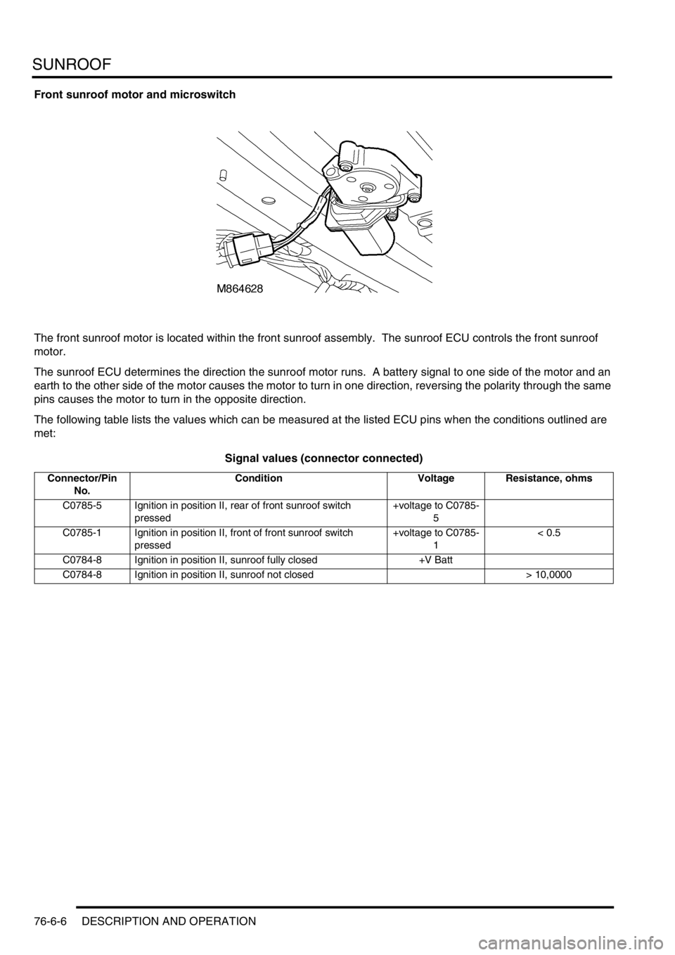
Front sunroof motor and microswitch
The front sunroof motor is located within the front sunroof assembly. The sunroof ECU controls the front sunroof
motor.
The sunroof ECU determines the direction the sunroof motor runs. A battery signal to one side of the motor and an
earth to the other side of the motor causes the motor to turn in one direction, reversing the polarity through the same
pins causes the motor to turn in the opposite direction.
The following table lists the values which can be measured at the listed ECU pins when the conditions outlined are
met:
Signal values (connector connected)
Connector/Pin
No.Condition Voltage Resistance, ohms
C0785-5 Ignition in position II, rear of front sunroof switch
pressed+voltage to C0785-
5
C0785-1 Ignition in position II, front of front sunroof switch
pressed+voltage to C0785-
1< 0.5
C0784-8 Ignition in position II, sunroof fully closed +V Batt
C0784-8 Ignition in position II, sunroof not closed > 10,0000