Page 959 of 1672

FRONT SUSPENSION
60-20 DESCRIPTION AND OPERATION
ACE Electronic control unit (ECU)
1Body Control Unit (Ref. only)
2Bracket
3ACE Electronic control unit
4Attachment nuts 3 off
The ACE ECU is mounted on a bracket behind the passenger glove box and is identified from the other ECU's by its
single electrical harness connector. The single 36 pin connector is located on the lower face of the ECU and mates
with a connector from the main harness. The connector supplies power, ground, signal and sensor information to/from
the ECU for control of the ACE system.
The ACE ECU receives a battery power supply from fuse 15 in the engine compartment fusebox via the ACE relay,
also located in the engine compartment fusebox. The ECU provides an earth path for the relay coil, energising the
coil and supplying power to the ECU.
An ignition on signal is supplied from the ignition switch via fuse 29 in the passenger compartment fusebox. The
ignition on signal provides an input to the ECU which tells the ECU that ignition has been selected on and initiates a
250 ms start time. The start time is used to prevent functions operating when software routines are being initialised.
The ignition on signal, when removed, tells the ECU that the ignition is off. The ECU will remain powered for thirty
seconds after the ignition is turned off. The thirty second period allows the ECU to store values and fault flags in the
memory. These values are read by the ECU when the next ignition on signal is received.
An engine speed signal is transmitted to the ECU from the Engine Control Module (ECM) as a pulsed digital signal.
The engine speed signal is used by the ACE ECU to detect that the engine is running and hydraulic pressure for ACE
system operation is available.
Page 962 of 1672

FRONT SUSPENSION
DESCRIPTION AND OPERATION 60-23
Road speed signal
Engine speed signal
Reverse gear signal
Ignition ON signal
Pressure control valve failure
Failure Effect
Open circuit No ACE control - 'Locked bars' condition
Short circuit - Ground No ACE control - 'Locked bars' condition
Short circuit - VBatt No ACE control - 'Locked bars' condition
Failure Effect
Open circuit No ACE control - 'Locked bars' condition
Short circuit - Ground No ACE control - 'Locked bars' condition
Short circuit - VBatt No ACE control - 'Locked bars' condition
Failure Effect
Open circuit No reverse signal to ECU. ACE active in reverse, may give
abnormal handling when reversing
Short circuit - Ground No reverse signal to ECU. ACE active in reverse, may give
abnormal handling when reversing
Short circuit - VBatt Permanent reverse signal to ECU. Permanent 'Locked
bars' condition
Failure Effect
Open circuit ECU does not receive ignition ON signal. No ARC control,
'Locked bars' condition
Short circuit - Ground ECU does not receive ignition ON signal. No ARC control,
'Locked bars' condition
Short circuit - VBatt Permanent ignition ON signal to ECU. Possibility of flat
battery
Failure Effect
Open circuit No ACE control
Short circuit - Ground No ACE control
Short circuit - VBatt No ACE control
Valve stuck open No ACE control
Valve stuck closed Maximum system pressure - no proportional control.
Pressure relief valve operating at 185 bar (2683 lbf.in
2)
Page 1016 of 1672
REAR SUSPENSION
DESCRIPTION AND OPERATION 64-11
1Battery supply (via SLABS relay)
2Ignition supply
3RH height sensor
4LH height sensor
5Off-road mode warning lamp
6Audible warning speaker
7Instrument pack
8SLS warning lamp
9Fusible link 9
10SLS relay
11Air supply unit12RH air valve
13LH air valve
14Exhaust valve
15Diagnostic socket
16Off-road mode switch
17SLS remote handset
18Body Control Unit (BCU)
19Door switches
20SLABS ECU
21Engine Control Module (ECM)
Page 1022 of 1672

REAR SUSPENSION
DESCRIPTION AND OPERATION 64-17
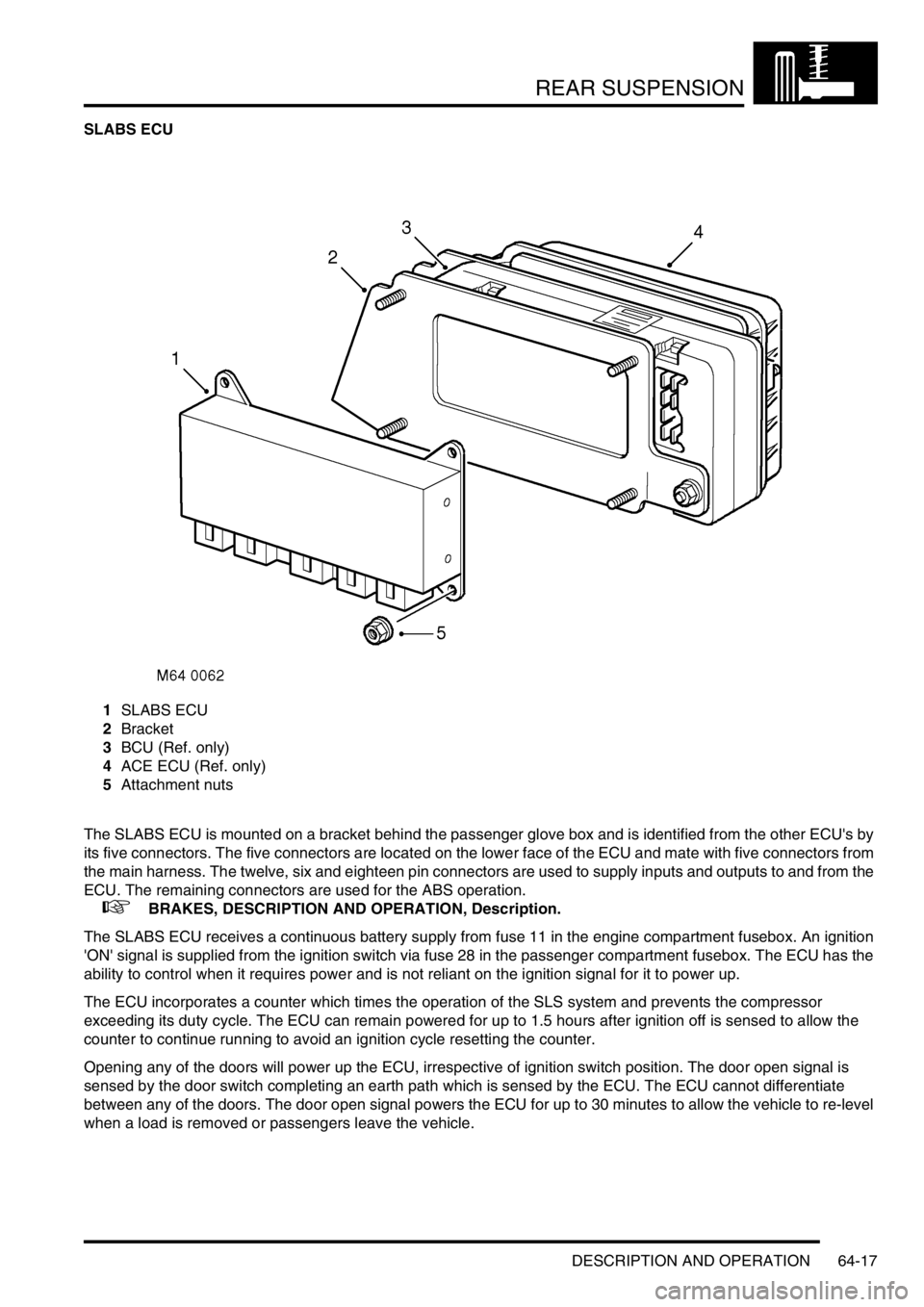
SLABS ECU
1SLABS ECU
2Bracket
3BCU (Ref. only)
4ACE ECU (Ref. only)
5Attachment nuts
The SLABS ECU is mounted on a bracket behind the passenger glove box and is identified from the other ECU's by
its five connectors. The five connectors are located on the lower face of the ECU and mate with five connectors from
the main harness. The twelve, six and eighteen pin connectors are used to supply inputs and outputs to and from the
ECU. The remaining connectors are used for the ABS operation.
+ BRAKES, DESCRIPTION AND OPERATION, Description.
The SLABS ECU receives a continuous battery supply from fuse 11 in the engine compartment fusebox. An ignition
'ON' signal is supplied from the ignition switch via fuse 28 in the passenger compartment fusebox. The ECU has the
ability to control when it requires power and is not reliant on the ignition signal for it to power up.
The ECU incorporates a counter which times the operation of the SLS system and prevents the compressor
exceeding its duty cycle. The ECU can remain powered for up to 1.5 hours after ignition off is sensed to allow the
counter to continue running to avoid an ignition cycle resetting the counter.
Opening any of the doors will power up the ECU, irrespective of ignition switch position. The door open signal is
sensed by the door switch completing an earth path which is sensed by the ECU. The ECU cannot differentiate
between any of the doors. The door open signal powers the ECU for up to 30 minutes to allow the vehicle to re-level
when a load is removed or passengers leave the vehicle.
Page 1023 of 1672

REAR SUSPENSION
64-18 DESCRIPTION AND OPERATION
The ECU supplies a 5 V current to each of the height sensors. Each height sensor uses the current to supply an
analogue input to the ECU. The ECU can calculate from the input received from each height sensor the height of the
vehicle and can then power the air supply unit as necessary to raise or lower one or both air springs to level the
vehicle.
When SLS compressor operation is required, the ECU provides a battery supply to energise the SLS relay located in
the engine compartment fusebox. When the relay contacts close, a 12 V supply passes through fusible link 9 in the
engine compartment fusebox, through the relay contacts and operates the air supply unit compressor. The ECU will
then supply power to operate one or both air control valve solenoids and/or the exhaust valve solenoid to inflate or
deflate the air springs as required. The compressor does not need to be powered to deflate the air springs.
The ECU also controls the operation of the SLS audible warning, the SLS warning lamp and the ORM warning lamp.
When the ignition is switched to position II, the ECU performs a three second bulb check and illuminates the SLS and
ORM warning lamps in the instrument pack to check for operation. When the system is operating or a fault is sensed
by the ECU, the ECU will operate the appropriate warning lamp and audible warning as required. The audible warning
is operated by the Body Control Unit (BCU) when it receives a signal from the SLABS ECU. The audible warning is
emitted from a speaker at the rear of the instrument pack.
Depressing the ORM switch for a minimum of 0.5 seconds, completes an earth which the ECU uses as a signal to
initiate the ORM if conditions allow. When the ECU starts ORM, the same earth that was completed by the ORM
switch is pulled to earth by the ECU to activate the ORM warning lamp. The ECU checks for a further operation of the
ORM switch by continuously and very quickly removing the earth for the ORM warning lamp. If the ORM switch is
operated for more than 0.5 seconds, the ECU will detect this and de-activate the ORM.
The SLS part of the SLABS ECU also uses the road speed data generated within the SLABS ECU by the ABS system.
Operation of ORM and extended mode are road speed sensitive and use the ABS signal to monitor the vehicle speed.
When the accessory remote handset is used for the SLS lower and raise functions, the handset transmits RF signals
which are received by the same RF receiver used for the alarm/remote door locking system. The RF receiver passes
this data as a 25 Hz PWM signal to the BCU. The BCU then transmits this data to the SLABS ECU as raise or lower
data. TestBook is required to program the BCU for remote handset operation.
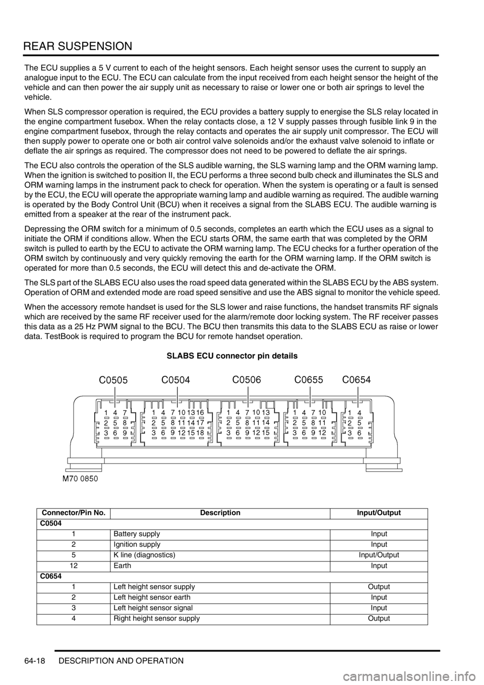
SLABS ECU connector pin details
Connector/Pin No. Description Input/Output
C0504
1 Battery supply Input
2 Ignition supply Input
5 K line (diagnostics) Input/Output
12 EarthInput
C0654
1 Left height sensor supply Output
2 Left height sensor earth Input
3 Left height sensor signal Input
4 Right height sensor supply Output
Page 1048 of 1672
BRAKES
DESCRIPTION AND OPERATION 70-3
1ABS sensor
2ABS modulator
3Return pump relay
4SLABS ECU
5Brake lamp relay
6Centre high mounted stop lamp
7LH brake lamp
8RH brake lamp
9Instrument pack
10Body control unit
11Reverse lamp switch (manual gearbox)
12Diagnostic socket
13HDC switch
14Transmission high/low switch
15Centre differential lock switch
16Engine control module
17Battery power supply
18Ignition power supply
Page 1062 of 1672

BRAKES
DESCRIPTION AND OPERATION 70-17
SLABS ECU
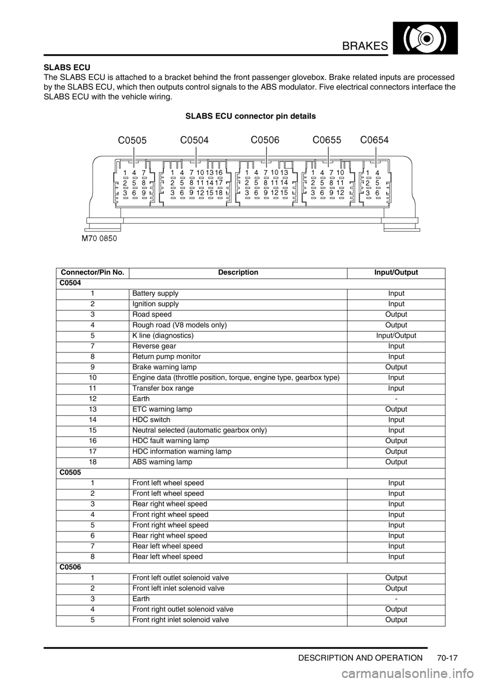
The SLABS ECU is attached to a bracket behind the front passenger glovebox. Brake related inputs are processed
by the SLABS ECU, which then outputs control signals to the ABS modulator. Five electrical connectors interface the
SLABS ECU with the vehicle wiring.
SLABS ECU connector pin details
Connector/Pin No. Description Input/Output
C0504
1 Battery supply Input
2 Ignition supply Input
3 Road speed Output
4 Rough road (V8 models only) Output
5 K line (diagnostics) Input/Output
7 Reverse gear Input
8 Return pump monitor Input
9 Brake warning lamp Output
10 Engine data (throttle position, torque, engine type, gearbox type) Input
11 Transfer box range Input
12 Earth-
13 ETC warning lamp Output
14 HDC switch Input
15 Neutral selected (automatic gearbox only) Input
16 HDC fault warning lamp Output
17 HDC information warning lamp Output
18 ABS warning lamp Output
C0505
1 Front left wheel speed Input
2 Front left wheel speed Input
3 Rear right wheel speed Input
4 Front right wheel speed Input
5 Front right wheel speed Input
6 Rear right wheel speed Input
7 Rear left wheel speed Input
8 Rear left wheel speed Input
C0506
1 Front left outlet solenoid valve Output
2 Front left inlet solenoid valve Output
3Earth-
4 Front right outlet solenoid valve Output
5 Front right inlet solenoid valve Output
Page 1099 of 1672

RESTRAINT SYSTEMS
75-4 DESCRIPTION AND OPERATION
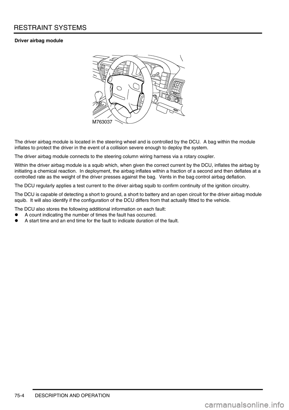
Driver airbag module
The driver airbag module is located in the steering wheel and is controlled by the DCU. A bag within the module
inflates to protect the driver in the event of a collision severe enough to deploy the system.
The driver airbag module connects to the steering column wiring harness via a rotary coupler.
Within the driver airbag module is a squib which, when given the correct current by the DCU, inflates the airbag by
initiating a chemical reaction. In deployment, the airbag inflates within a fraction of a second and then deflates at a
controlled rate as the weight of the driver presses against the bag. Vents in the bag control airbag deflation.
The DCU regularly applies a test current to the driver airbag squib to confirm continuity of the ignition circuitry.
The DCU is capable of detecting a short to ground, a short to battery and an open circuit for the driver airbag module
squib. It will also identify if the configuration of the DCU differs from that actually fitted to the vehicle.
The DCU also stores the following additional information on each fault:
lA count indicating the number of times the fault has occurred.
lA start time and an end time for the fault to indicate duration of the fault.