Page 265 of 1672

ENGINE - V8
12-2-22 REPAIRS
Mounting - front - LH
$% 12.45.01
Remove
1.Release turnbuckles and remove battery cover.
2.Disconnect battery earth lead.
3.Raise front of vehicle.
WARNING: Do not work on or under a
vehicle supported only by a jack. Always
support the vehicle on safety stands.
4.Remove underbelly panel.
+ EXTERIOR FITTINGS, REPAIRS,
Panel - underbelly.
5.Position a jack beneath the sump, and support
the engine on the jack.
CAUTION: To prevent damage to
components, cushion the jack pad with a
block of wood or hard rubber.
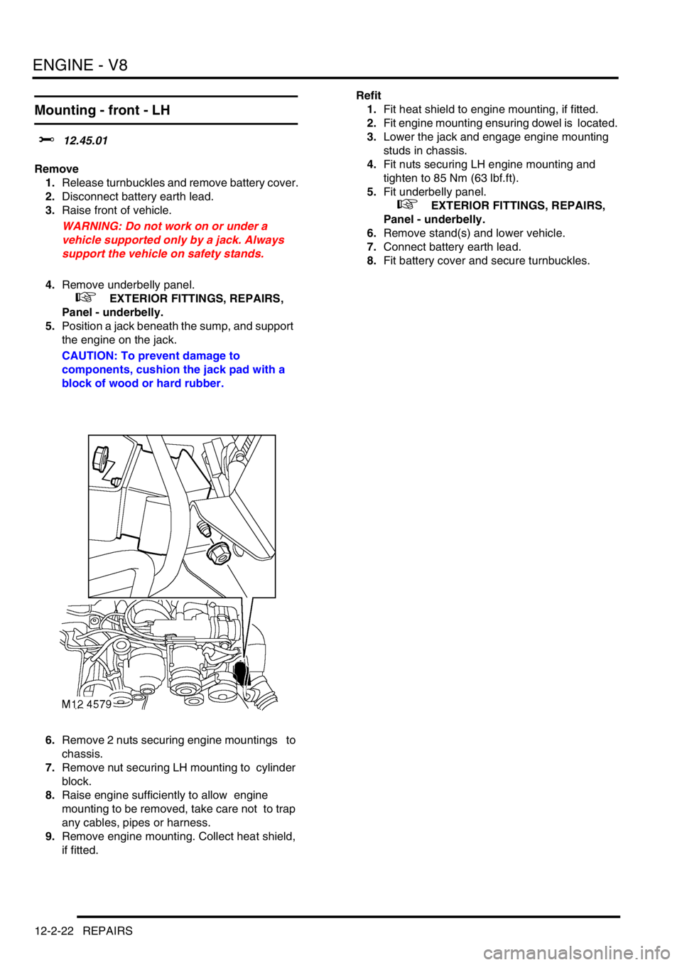
6.Remove 2 nuts securing engine mountings to
chassis.
7.Remove nut securing LH mounting to cylinder
block.
8.Raise engine sufficiently to allow engine
mounting to be removed, take care not to trap
any cables, pipes or harness.
9.Remove engine mounting. Collect heat shield,
if fitted.Refit
1.Fit heat shield to engine mounting, if fitted.
2.Fit engine mounting ensuring dowel is located.
3.Lower the jack and engage engine mounting
studs in chassis.
4.Fit nuts securing LH engine mounting and
tighten to 85 Nm (63 lbf.ft).
5.Fit underbelly panel.
+ EXTERIOR FITTINGS, REPAIRS,
Panel - underbelly.
6.Remove stand(s) and lower vehicle.
7.Connect battery earth lead.
8.Fit battery cover and secure turnbuckles.
Page 266 of 1672

ENGINE - V8
REPAIRS 12-2-23
Mounting - front - RH
$% 12.45.03
Remove
1.Release turnbuckles and remove battery cover.
2.Disconnect battery earth lead.
3.Raise front of vehicle.
WARNING: Do not work on or under a
vehicle supported only by a jack. Always
support the vehicle on safety stands.
4.Remove underbelly panel.
+ EXTERIOR FITTINGS, REPAIRS,
Panel - underbelly.
5.Position a jack beneath the sump, and support
the engine on the jack.
CAUTION: To prevent damage to
components, cushion the jack pad with a
block of wood or hard rubber.
6.Remove 2 nuts securing engine mountings to
chassis.
7.Remove nut securing RH mounting to cylinder
block.
8.Raise engine sufficiently to allow engine
mounting to be removed. Take care not to trap
any cables, pipes or harness.
9.Remove engine mounting.
10.Collect heat shield. Refit
1.Position heat shield.
2.Fit engine mounting ensuring dowel is located.
3.Lower the jack and engage engine mounting
studs in chassis.
4.Fit engine mounting nuts and tighten to 85 Nm
(63 lbf.ft).
5.Fit underbelly panel.
+ EXTERIOR FITTINGS, REPAIRS,
Panel - underbelly.
6.Remove stand(s) and lower vehicle.
7.Connect battery earth lead.
8.Fit battery cover and secure turnbuckles.
Page 267 of 1672

ENGINE - V8
12-2-24 REPAIRS
Mounting - rear - LH
$% 12.45.07
Remove
1.Raise vehicle on lift.
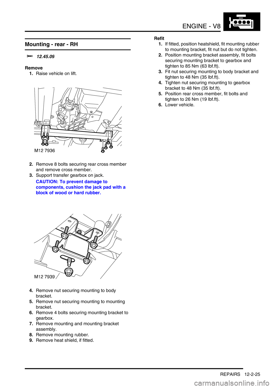
2.Remove 8 bolts securing rear cross member
and remove cross member.
3.Support transfer gearbox on jack.
CAUTION: To prevent damage to
components, cushion the jack pad with a
block of wood or hard rubber.
4.Release and disconnect HO2S multiplug.5.Remove nut securing mounting to body
bracket.
6.Remove nut securing mounting to mounting
bracket.
7.Remove 4 bolts securing mounting bracket to
gearbox.
8.Remove mounting and mounting bracket
assembly.
9.Remove mounting rubber.
10.Remove heat shield, if fitted.
Refit
1.If fitted position heatshield, fit mounting rubber
to mounting bracket, fit nut but do not tighten.
2.Position mounting bracket assembly, fit bolts
securing mounting bracket to gearbox and
tighten to 85 Nm (63 lbf.ft).
3.Fit nut securing mounting to body bracket and
tighten to 48 Nm (35 lbf.ft).
4.Tighten nut securing mounting to gearbox
bracket to 48 Nm (35 lbf.ft).
5.Connect HO2S multiplug and secure to support
bracket.
6.Position rear cross member, fit bolts and
tighten to 26 Nm (19 lbf.ft).
7.Lower vehicle.
Page 268 of 1672

ENGINE - V8
REPAIRS 12-2-25
Mounting - rear - RH
$% 12.45.09
Remove
1.Raise vehicle on lift.
2.Remove 8 bolts securing rear cross member
and remove cross member.
3.Support transfer gearbox on jack.
CAUTION: To prevent damage to
components, cushion the jack pad with a
block of wood or hard rubber.
4.Remove nut securing mounting to body
bracket.
5.Remove nut securing mounting to mounting
bracket.
6.Remove 4 bolts securing mounting bracket to
gearbox.
7.Remove mounting and mounting bracket
assembly.
8.Remove mounting rubber.
9.Remove heat shield, if fitted.Refit
1.If fitted, position heatshield, fit mounting rubber
to mounting bracket, fit nut but do not tighten.
2.Position mounting bracket assembly, fit bolts
securing mounting bracket to gearbox and
tighten to 85 Nm (63 lbf.ft).
3.Fit nut securing mounting to body bracket and
tighten to 48 Nm (35 lbf.ft).
4.Tighten nut securing mounting to gearbox
bracket to 48 Nm (35 lbf.ft).
5.Position rear cross member, fit bolts and
tighten to 26 Nm (19 lbf.ft).
6.Lower vehicle.
Page 280 of 1672

ENGINE - V8
REPAIRS 12-2-37
9.Remove 2 clips securing oil cooler pipes at
front of sump.
10.Remove clip securing oil cooler pipes to side of
sump.
11.Remove clip bracket.
12.Remove 2 forward facing bolts securing sump
to bell housing.
13.Remove 4 rear facing bolts securing sump to
bell housing.
14.Remove 2 bolts in sump recess.
15.Remove 3 nuts securing front of sump. 16.Remove 12 bolts securing sump flange to
engine.
17.Manoeuvre sump over front axle and remove
sump.
18.Discard sump gasket.
Refit
1.Clean all traces of sealant from the sump and
sump mating faces using a plastic scraper or
solvent.
2.Apply a 5 mm wide bead of sealant, Part No.
STC 50550, across the cylinder block to front
cover joint and across the cylinder block to rear
main bearing joint. Apply a globule of sealant to
cover the end of the cruciform seal, (see
illustration).
3.Fit new gasket, dry, to sump, ensuring that
locating tags are correctly positioned.
4.Manoeuvre sump into position, fit and lightly
tighten 2 bolts to retain sump in place, then fit
and lightly tighten remainder of bolts.
5.Working in the sequence illustrated, tighten the
sump bolts to 22 Nm (16 lbf.ft).
6.Position side clip bracket, fit and tighten bolt.
7.Position oil cooler pipe clips, fit and tighten
nuts.
Page 284 of 1672

ENGINE - V8
REPAIRS 12-2-41
7.Release clip and disconnect coolant hose from
coolant pump.
8.Disconnect multiplug from oil pressure switch.
9.Disconnect multiplug from CMP sensor.
10. If fitted: Loosen union and disconnect oil
cooler pipe from timing gear cover. Remove
and discard 'O' ring.
CAUTION: Always fit plugs to open
connections to prevent contamination.11.Remove 9 bolts securing timing gear cover and
remove cover. Remove and discard gasket.
Refit
1.Clean mating faces of timing gear cover and
cylinder block. Clean dowels and dowel holes.
2.Fit new gasket, dry, to dowels in cylinder block.
3.Fit timing gear cover to cylinder block and,
working the sequence illustrated, tighten bolts
to 22 Nm (17 lbf.ft) . Ensure CMP sensor
multiplug bracket is secured by bolt.
4. If fitted: Fit new 'O' ring to oil cooler pipe,
connect pipe to timing gear cover and tighten
union to 15 Nm (11 lbf.ft).
5.Connect multiplug to oil pressure switch.
6.Connect multiplug to CMP sensor.
7.Connect coolant hose to coolant pump and
secure with clip.
Page 285 of 1672

ENGINE - V8
12-2-42 REPAIRS
8.Ensure mating faces of PAS pump pulley and
drive flange are clean, fit pulley and tighten
bolts to 22 Nm (16 lbf.ft).
9.Remove all traces of thread locking material
from coolant pump pulley drive flange bolt
holes using an M8 tap.
10.Ensure mating faces of coolant pump pulley
and drive flange are clean, fit pulley and tighten
new Patchlok bolts to 22 Nm (16 lbf.ft).
11.Ensure mating faces of oil filter and adaptor are
clean, smear clean engine oil onto seal and fit
filter.
12.Fit timing gear cover oil seal.
+ ENGINE - V8, REPAIRS, Seal - cover
- timing gears.
13.Fit oil pick-up strainer.
+ ENGINE - V8, REPAIRS, Strainer -
oil pick-up.
14.Refill cooling system.
+ COOLING SYSTEM - V8,
ADJUSTMENTS, Drain and refill.
Seal - cover - timing gears
$% 12.65.05
Remove
1.Remove auxiliary drive belt.
+ CHARGING AND STARTING,
REPAIRS, Belt - auxiliary drive.
2.Secure tool LRT-12-080 to crankshaft pulley
with 2 bolts.
3.Remove crankshaft pulley bolt.
4.Remove crankshaft pulley.
5.Use tool LRT-12-088, to remove oil seal from
timing gear cover.
Page 290 of 1672

ENGINE - V8
OVERHAUL 12-2-47
15.Remove 2 bolts securing manifold gasket and
collect gasket clamps.
16.Remove inlet manifold gasket.
17.Remove gasket seals. Reassembly
1.Clean sealant from cylinder head and from
notches in the cylinder block.
2.Clean mating faces of cylinder block, cylinder
head and manifold.
CAUTION: Do not use a metal scraper or
machined surfaces may be damaged.
3.Apply sealant, Part No. STC 3254 to cylinder
head and notches in cylinder block.
4.Fit new gasket seals, ensuring the ends
engage correctly in notches.
5.Apply sealant, Part No. STC 3254 to gasket
seals above the notches in the cylinder block.
6.Fit new manifold gasket, dry.
7.Position gasket clamps, fit and lightly tighten
bolts.
8.Position inlet manifold assembly to cylinder
head.
9.Fit manifold bolts and, working in the sequence
illustrated, tighten as follows:
lInitially, tighten bolts numbered 1, 4, 9 and
12 in numerical order to 5 Nm (4 lbf.ft).
lInlet manifold bolts - initial tighten = 10 Nm
(8 lbf.ft).
lInlet manifold bolts - final tighten = 51 Nm
(38 lbf.ft).
lTighten inlet manifold gasket clamp bolts to
18 Nm (14 lbf.ft).
lTighten inlet manifold bolts to 51 Nm (38
lbf.ft)