Page 1098 of 1672
RESTRAINT SYSTEMS
DESCRIPTION AND OPERATION 75-3
Description - SRS
General
The purpose of the Supplementary Restraint System (SRS) is to reduce the impact of the driver and passenger
against the vehicle's interior in the event of a serious accident.
The SRS system is a stand-alone system. There are no remotely mounted crash sensors. The only external input to
the DCU is power. The system only becomes live when the ignition is switched on.
The SRS consists of the following components:
lDiagnostic and control unit (DCU).
lSRS warning lamp.
lRotary coupler.
lDriver airbag module.
lDriver seat belt pretensioner.
lPassenger airbag module.
lPassenger seat belt pretensioner.
The passenger airbag is optional in some markets. All other components are standard fit in all markets. The SRS
functions the same in all markets.
Page 1099 of 1672

RESTRAINT SYSTEMS
75-4 DESCRIPTION AND OPERATION
Driver airbag module
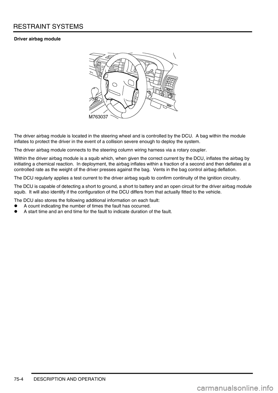
The driver airbag module is located in the steering wheel and is controlled by the DCU. A bag within the module
inflates to protect the driver in the event of a collision severe enough to deploy the system.
The driver airbag module connects to the steering column wiring harness via a rotary coupler.
Within the driver airbag module is a squib which, when given the correct current by the DCU, inflates the airbag by
initiating a chemical reaction. In deployment, the airbag inflates within a fraction of a second and then deflates at a
controlled rate as the weight of the driver presses against the bag. Vents in the bag control airbag deflation.
The DCU regularly applies a test current to the driver airbag squib to confirm continuity of the ignition circuitry.
The DCU is capable of detecting a short to ground, a short to battery and an open circuit for the driver airbag module
squib. It will also identify if the configuration of the DCU differs from that actually fitted to the vehicle.
The DCU also stores the following additional information on each fault:
lA count indicating the number of times the fault has occurred.
lA start time and an end time for the fault to indicate duration of the fault.
Page 1100 of 1672

RESTRAINT SYSTEMS
DESCRIPTION AND OPERATION 75-5
Passenger airbag module
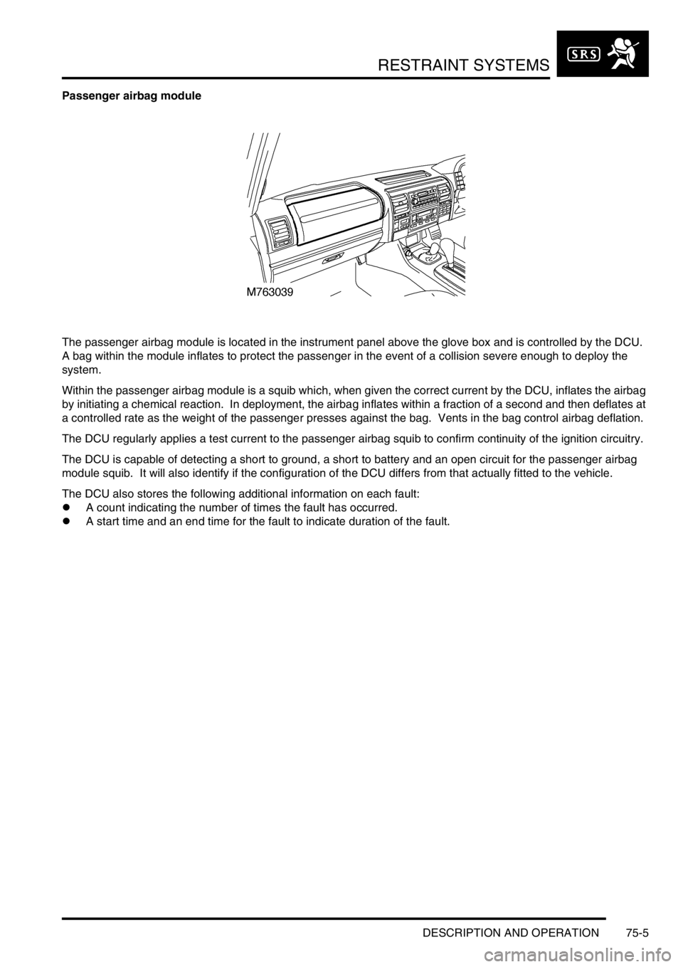
The passenger airbag module is located in the instrument panel above the glove box and is controlled by the DCU.
A bag within the module inflates to protect the passenger in the event of a collision severe enough to deploy the
system.
Within the passenger airbag module is a squib which, when given the correct current by the DCU, inflates the airbag
by initiating a chemical reaction. In deployment, the airbag inflates within a fraction of a second and then deflates at
a controlled rate as the weight of the passenger presses against the bag. Vents in the bag control airbag deflation.
The DCU regularly applies a test current to the passenger airbag squib to confirm continuity of the ignition circuitry.
The DCU is capable of detecting a short to ground, a short to battery and an open circuit for the passenger airbag
module squib. It will also identify if the configuration of the DCU differs from that actually fitted to the vehicle.
The DCU also stores the following additional information on each fault:
lA count indicating the number of times the fault has occurred.
lA start time and an end time for the fault to indicate duration of the fault.
Page 1101 of 1672
RESTRAINT SYSTEMS
75-6 DESCRIPTION AND OPERATION
Seat belt pretensioners
The seat belt pretensioners are located within the front seat belt anchors and are controlled by the DCU. They are
pyrotechnic devices that, when deployed, tighten the front seat belts. This works in conjunction with the airbag
module(s) to protect front seat occupants in the event of an accident.
The DCU regularly applies a test current to the seat belt pretensioner squibs to confirm continuity of the ignition
circuitry.
The DCU is capable of detecting a short to ground, a short to battery and an open circuit for the squibs. It will also
identify if the configuration of the DCU differs from that actually fitted to the vehicle.
The DCU also stores the following additional information on each fault:
lA count indicating the number of times the fault has occurred.
lA start time and an end time for the fault to indicate duration of the fault.
Page 1103 of 1672

RESTRAINT SYSTEMS
75-8 DESCRIPTION AND OPERATION
Diagnostic and Control Unit (DCU)
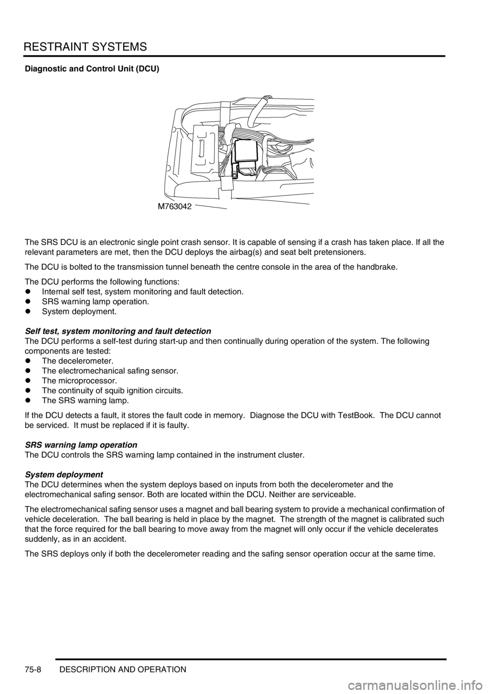
The SRS DCU is an electronic single point crash sensor. It is capable of sensing if a crash has taken place. If all the
relevant parameters are met, then the DCU deploys the airbag(s) and seat belt pretensioners.
The DCU is bolted to the transmission tunnel beneath the centre console in the area of the handbrake.
The DCU performs the following functions:
lInternal self test, system monitoring and fault detection.
lSRS warning lamp operation.
lSystem deployment.
Self test, system monitoring and fault detection
The DCU performs a self-test during start-up and then continually during operation of the system. The following
components are tested:
lThe decelerometer.
lThe electromechanical safing sensor.
lThe microprocessor.
lThe continuity of squib ignition circuits.
lThe SRS warning lamp.
If the DCU detects a fault, it stores the fault code in memory. Diagnose the DCU with TestBook. The DCU cannot
be serviced. It must be replaced if it is faulty.
SRS warning lamp operation
The DCU controls the SRS warning lamp contained in the instrument cluster.
System deployment
The DCU determines when the system deploys based on inputs from both the decelerometer and the
electromechanical safing sensor. Both are located within the DCU. Neither are serviceable.
The electromechanical safing sensor uses a magnet and ball bearing system to provide a mechanical confirmation of
vehicle deceleration. The ball bearing is held in place by the magnet. The strength of the magnet is calibrated such
that the force required for the ball bearing to move away from the magnet will only occur if the vehicle decelerates
suddenly, as in an accident.
The SRS deploys only if both the decelerometer reading and the safing sensor operation occur at the same time.
Page 1104 of 1672

RESTRAINT SYSTEMS
DESCRIPTION AND OPERATION 75-9
Operation - SRS
The diagnostic and control unit (DCU) controls the SRS system. The DCU is located beneath the centre console close
to the handbrake area. The DCU contains both an electronic deceleration sensor as well as an electromechanical
safing sensor. When the electronic deceleration sensor within the DCU detects rapid deceleration of the vehicle, it
compares the deceleration rate with stored values in its' memory. If the deceleration rate exceeds the stored value
and the electromechanical safing sensor triggers, the DCU deploys the airbag and the seat belt pretensioners. The
DCU will not deploy the airbags and seat belt pretensioners unless both sensors trigger.
The SRS has diagnostic capabilities through TestBook. In the event that a fault is detected, the DCU alerts the driver
by illuminating a warning lamp in the instrument cluster.
The DCU controls the following:
lSRS warning lamp.
lDrivers airbag module.
lPassenger airbag module (where fitted).
lDriver seat belt pretensioner.
lPassenger seat belt pretensioner.
WARNING: The integrity of the SRS system are critical for safety reasons. Ensure the following precautions
are always adhered to:
lNever install used SRS components from another vehicle or attempt to repair an SRS component.
lWhen repairing an SRS system only use genuine new parts.
lNever apply electrical power to an SRS component unless instructed to do so as part of an approved test
procedure.
lSpecial Torx bolts are necessary for installing the airbag module - do not use other bolts. Ensure bolts
are tightened to the correct torque.
lAlways use new fixings when replacing an SRS component.
lEnsure the SRS Diagnostic Control Unit (DCU) is always installed correctly. There must not be any gap
between the DCU and the bracket to which it is mounted. An incorrectly mounted DCU could cause the
system to malfunction.
System deployment
The airbag and seat belt pretensioners deploy to protect the front seat occupants when the DCU senses a rapid
vehicle deceleration. The system deploys when the following conditions are met:
lThe ignition switch is on.
lThe vehicle decelerates beyond a threshold defined within the DCU.
lThe electromechanical safing sensor within the DCU triggers.
When all of the above conditions are met, the DCU deploys the airbag(s) and seat belt pretensioners. If the above
conditions are not met, the DCU will not deploy the system.
Component replacement policy
After an impact which deploys the airbags and pretensioners, the following components must be renewed:
lDCU.
lDriver and passenger airbag modules.
lDriver and passenger buckle pretensioners.
lRotary coupler.
lFlyleads (where applicable) connecting airbags and pre-tensioners to SRS harness
Page 1105 of 1672
RESTRAINT SYSTEMS
75-10 DESCRIPTION AND OPERATION
SRS warning lamp
The SRS warning lamp illuminates for 5 seconds during system readiness check on starting the engine. The SRS
warning lamp extinguishes for one second after the system readiness check is performed. If a fault is present the
warning lamp then illuminates continuously. If no fault is present, the SRS warning lamp remains extinguished. If a
system fault occurs in excess of two seconds after the readiness check has been completed, the SRS warning lamp
illuminates for that ignition cycle. It remains illuminated for a minimum of 12 seconds
± 4 seconds for all fault
conditions.
The SRS warning lamp will only illuminate for low voltage concerns while the low voltage condition is present. If the
low voltage condition is corrected, the SRS warning lamp extinguishes and the fault is recorded in the DCU's memory.
Page 1188 of 1672
SEATS
DESCRIPTION AND OPERATION 76-5-3
1Ignition switch
2BCU
3Driver door switch
4Left seat power relay
5Left seat satellite fuse box
6Left seat switch pack
7Left seat fore/ aft motor
8Left seat cushion front up/ down motor
9Left seat cushion rear up/ down motor
10Left seat squab fore/ aft motor
11Left seat lumbar pump
12Left seat lumbar deflate solenoid
13Right seat power relay
14Right seat satellite fuse box
15Right seat switch pack
16Right seat fore/ aft motor
17Right seat cushion front up/ down motor
18Right seat cushion rear up/ down motor
19Right seat squab fore/ aft motor
20Right seat lumbar pump
21Right seat lumbar deflate solenoid
22Passenger front door switch