2002 JEEP LIBERTY Electrical
[x] Cancel search: ElectricalPage 1625 of 1803
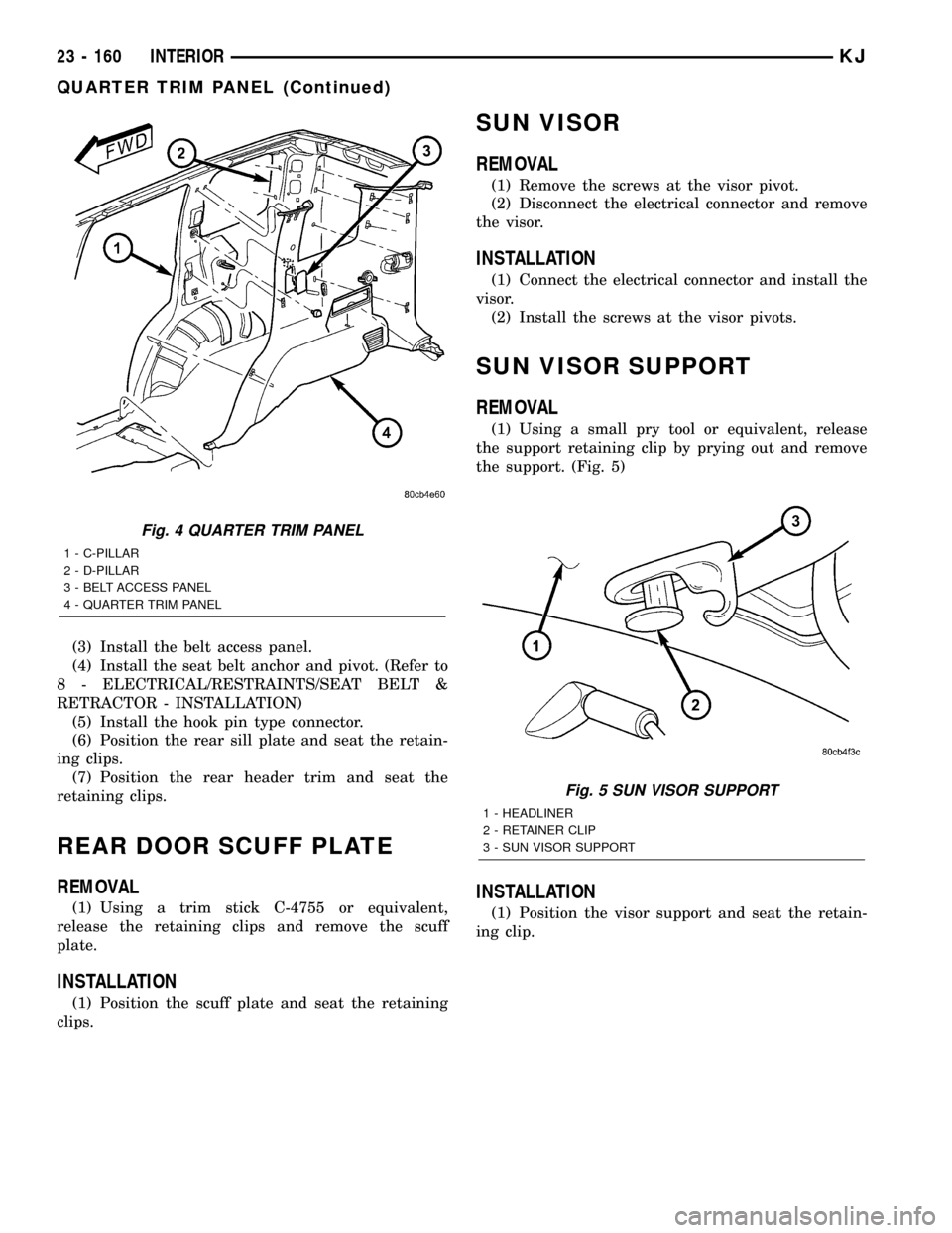
(3) Install the belt access panel.
(4) Install the seat belt anchor and pivot. (Refer to
8 - ELECTRICAL/RESTRAINTS/SEAT BELT &
RETRACTOR - INSTALLATION)
(5) Install the hook pin type connector.
(6) Position the rear sill plate and seat the retain-
ing clips.
(7) Position the rear header trim and seat the
retaining clips.
REAR DOOR SCUFF PLATE
REMOVAL
(1) Using a trim stick C-4755 or equivalent,
release the retaining clips and remove the scuff
plate.
INSTALLATION
(1) Position the scuff plate and seat the retaining
clips.
SUN VISOR
REMOVAL
(1) Remove the screws at the visor pivot.
(2) Disconnect the electrical connector and remove
the visor.
INSTALLATION
(1) Connect the electrical connector and install the
visor.
(2) Install the screws at the visor pivots.
SUN VISOR SUPPORT
REMOVAL
(1) Using a small pry tool or equivalent, release
the support retaining clip by prying out and remove
the support. (Fig. 5)
INSTALLATION
(1) Position the visor support and seat the retain-
ing clip.
Fig. 4 QUARTER TRIM PANEL
1 - C-PILLAR
2 - D-PILLAR
3 - BELT ACCESS PANEL
4 - QUARTER TRIM PANEL
Fig. 5 SUN VISOR SUPPORT
1 - HEADLINER
2 - RETAINER CLIP
3 - SUN VISOR SUPPORT
23 - 160 INTERIORKJ
QUARTER TRIM PANEL (Continued)
Page 1630 of 1803
SEAT - FRONT
REMOVAL
WARNING: DISABLE THE SUPPLEMENTAL
RESTRAINTS SYSTEM BEFORE ATTEMPTING ANY
STEERING WHEEL, STEERING COLUMN, DRIVER
AIRBAG, PASSENGER AIRBAG, SEAT BELT TEN-
SIONER, SIDE CURTAIN AIRBAG, OR INSTRUMENT
PANEL COMPONENT DIAGNOSIS OR SERVICE.
DISCONNECT AND ISOLATE THE BATTERY NEGA-
TIVE (GROUND) CABLE, THEN WAIT TWO MINUTES
FOR THE SYSTEM CAPACITOR TO DISCHARGE
BEFORE PERFORMING FURTHER DIAGNOSIS OR
SERVICE. THIS IS THE ONLY SURE WAY TO DIS-
ABLE THE SUPPLEMENTAL RESTRAINTS SYSTEM.
FAILURE TO TAKE THE PROPER PRECAUTIONS
COULD RESULT IN ACCIDENTAL AIRBAG DEPLOY-
MENT AND POSSIBLE PERSONAL INJURY.
WARNING: DURING AND FOLLOWING ANY SEAT
BELT SERVICE, CAREFULLY INSPECT ALL SEAT
BELTS, BUCKLES, MOUNTING HARDWARE, AND
RETRACTORS FOR PROPER INSTALLATION,
OPERATION, OR DAMAGE. REPLACE ANY BELT
THAT IS CUT, FRAYED, OR TORN. STRAIGHTEN
ANY BELT THAT IS TWISTED. TIGHTEN ANY
LOOSE FASTENERS. REPLACE ANY BELT THAT
HAS A DAMAGED OR INOPERATIVE BUCKLE OR
RETRACTOR. REPLACE ANY BELT THAT HAS A
BENT OR DAMAGED LATCH PLATE OR ANCHOR
PLATE. NEVER ATTEMPT TO REPAIR A SEAT BELT
COMPONENT. ALWAYS REPLACE DAMAGED OR
FAULTY SEAT BELT COMPONENTS WITH THE COR-
RECT, NEW AND UNUSED REPLACEMENT PARTS
LISTED IN THE MOPAR PARTS CATALOG.
(1) Remove the seat belt anchor bolt. (Refer to 8 -
ELECTRICAL/RESTRAINTS/SEAT BELT &
RETRACTOR - REMOVAL)
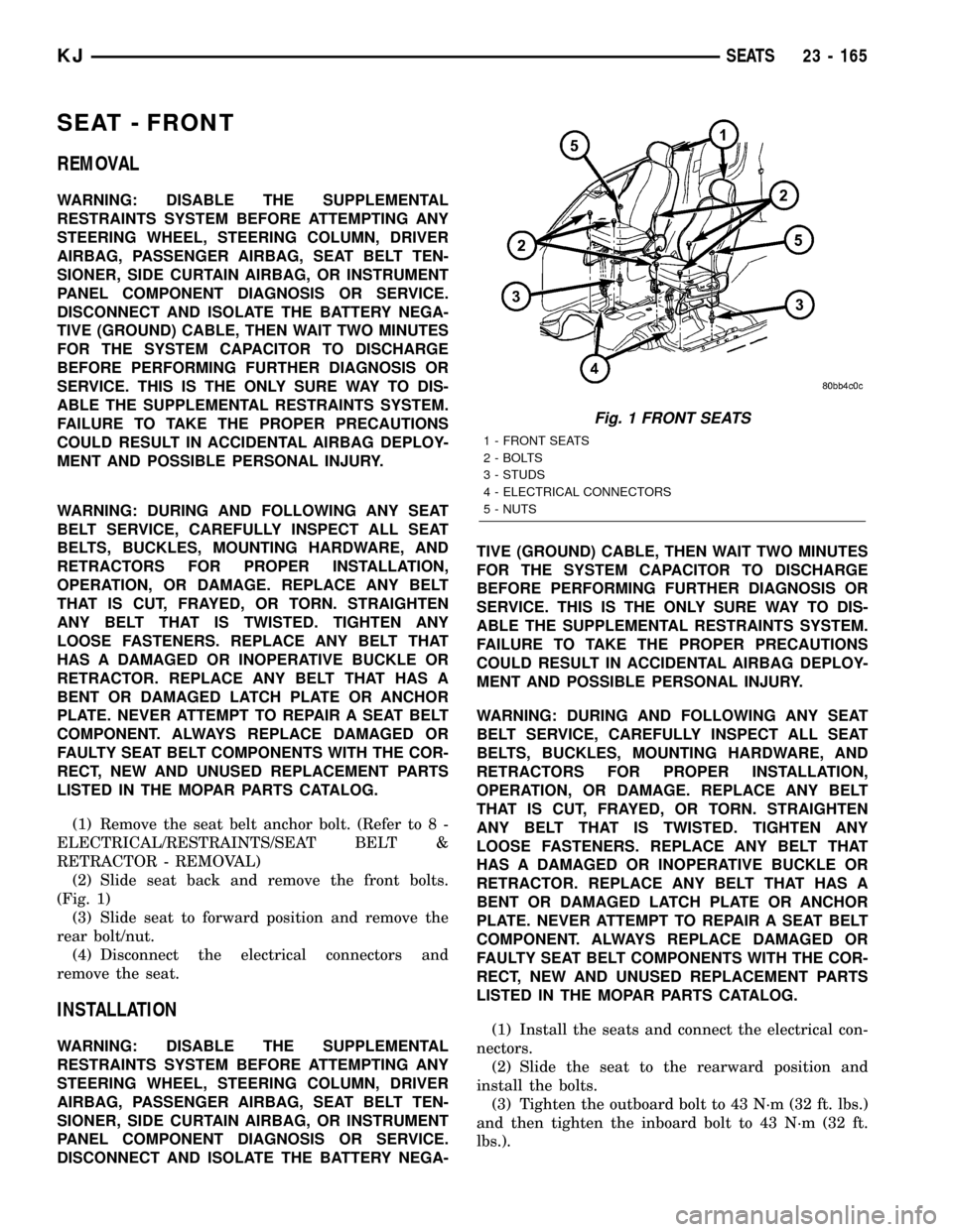
(2) Slide seat back and remove the front bolts.
(Fig. 1)
(3) Slide seat to forward position and remove the
rear bolt/nut.
(4) Disconnect the electrical connectors and
remove the seat.
INSTALLATION
WARNING: DISABLE THE SUPPLEMENTAL
RESTRAINTS SYSTEM BEFORE ATTEMPTING ANY
STEERING WHEEL, STEERING COLUMN, DRIVER
AIRBAG, PASSENGER AIRBAG, SEAT BELT TEN-
SIONER, SIDE CURTAIN AIRBAG, OR INSTRUMENT
PANEL COMPONENT DIAGNOSIS OR SERVICE.
DISCONNECT AND ISOLATE THE BATTERY NEGA-TIVE (GROUND) CABLE, THEN WAIT TWO MINUTES
FOR THE SYSTEM CAPACITOR TO DISCHARGE
BEFORE PERFORMING FURTHER DIAGNOSIS OR
SERVICE. THIS IS THE ONLY SURE WAY TO DIS-
ABLE THE SUPPLEMENTAL RESTRAINTS SYSTEM.
FAILURE TO TAKE THE PROPER PRECAUTIONS
COULD RESULT IN ACCIDENTAL AIRBAG DEPLOY-
MENT AND POSSIBLE PERSONAL INJURY.
WARNING: DURING AND FOLLOWING ANY SEAT
BELT SERVICE, CAREFULLY INSPECT ALL SEAT
BELTS, BUCKLES, MOUNTING HARDWARE, AND
RETRACTORS FOR PROPER INSTALLATION,
OPERATION, OR DAMAGE. REPLACE ANY BELT
THAT IS CUT, FRAYED, OR TORN. STRAIGHTEN
ANY BELT THAT IS TWISTED. TIGHTEN ANY
LOOSE FASTENERS. REPLACE ANY BELT THAT
HAS A DAMAGED OR INOPERATIVE BUCKLE OR
RETRACTOR. REPLACE ANY BELT THAT HAS A
BENT OR DAMAGED LATCH PLATE OR ANCHOR
PLATE. NEVER ATTEMPT TO REPAIR A SEAT BELT
COMPONENT. ALWAYS REPLACE DAMAGED OR
FAULTY SEAT BELT COMPONENTS WITH THE COR-
RECT, NEW AND UNUSED REPLACEMENT PARTS
LISTED IN THE MOPAR PARTS CATALOG.
(1) Install the seats and connect the electrical con-
nectors.
(2) Slide the seat to the rearward position and
install the bolts.
(3) Tighten the outboard bolt to 43 N´m (32 ft. lbs.)
and then tighten the inboard bolt to 43 N´m (32 ft.
lbs.).
Fig. 1 FRONT SEATS
1 - FRONT SEATS
2 - BOLTS
3 - STUDS
4 - ELECTRICAL CONNECTORS
5 - NUTS
KJSEATS 23 - 165
Page 1631 of 1803
(4) Slide the seat to the forward position and
install the rear bolt and nut.
(5) Tighten the fasteners to 43 N´m (32 ft. lbs.).
(6) Install the seat belt anchor and bolt. (Refer to
8 - ELECTRICAL/RESTRAINTS/SEAT BELT &
RETRACTOR - INSTALLATION)
SEAT BACK - FRONT
REMOVAL
(1) Remove the seat. (Refer to 23 - BODY/SEATS/
SEAT - FRONT - REMOVAL)
(2) Remove the seat cushion side shields. (Refer to
23 - BODY/SEATS/SEAT CUSHION SIDE SHIELDS
- REMOVAL)
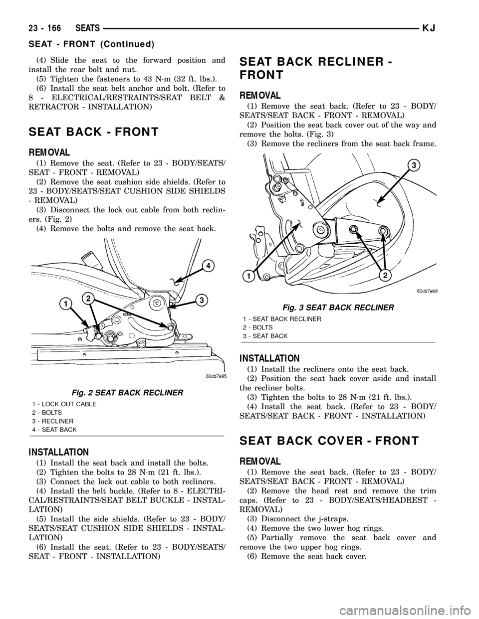
(3) Disconnect the lock out cable from both reclin-
ers. (Fig. 2)
(4) Remove the bolts and remove the seat back.
INSTALLATION
(1) Install the seat back and install the bolts.
(2) Tighten the bolts to 28 N´m (21 ft. lbs.).
(3) Connect the lock out cable to both recliners.
(4) Install the belt buckle. (Refer to 8 - ELECTRI-
CAL/RESTRAINTS/SEAT BELT BUCKLE - INSTAL-
LATION)
(5) Install the side shields. (Refer to 23 - BODY/
SEATS/SEAT CUSHION SIDE SHIELDS - INSTAL-
LATION)
(6) Install the seat. (Refer to 23 - BODY/SEATS/
SEAT - FRONT - INSTALLATION)
SEAT BACK RECLINER -
FRONT
REMOVAL
(1) Remove the seat back. (Refer to 23 - BODY/
SEATS/SEAT BACK - FRONT - REMOVAL)
(2) Position the seat back cover out of the way and
remove the bolts. (Fig. 3)
(3) Remove the recliners from the seat back frame.
INSTALLATION
(1) Install the recliners onto the seat back.
(2) Position the seat back cover aside and install
the recliner bolts.
(3) Tighten the bolts to 28 N´m (21 ft. lbs.).
(4) Install the seat back. (Refer to 23 - BODY/
SEATS/SEAT BACK - FRONT - INSTALLATION)
SEAT BACK COVER - FRONT
REMOVAL
(1) Remove the seat back. (Refer to 23 - BODY/
SEATS/SEAT BACK - FRONT - REMOVAL)
(2) Remove the head rest and remove the trim
caps. (Refer to 23 - BODY/SEATS/HEADREST -
REMOVAL)
(3) Disconnect the j-straps.
(4) Remove the two lower hog rings.
(5) Partially remove the seat back cover and
remove the two upper hog rings.
(6) Remove the seat back cover.
Fig. 2 SEAT BACK RECLINER
1 - LOCK OUT CABLE
2 - BOLTS
3 - RECLINER
4 - SEAT BACK
Fig. 3 SEAT BACK RECLINER
1 - SEAT BACK RECLINER
2 - BOLTS
3 - SEAT BACK
23 - 166 SEATSKJ
SEAT - FRONT (Continued)
Page 1633 of 1803
INSTALLATION
(1) Install the seat riser and install the bolts.
(2) Tighten the bolts to 28 N´m (21 ft. lbs.).
(3) Install a new release handle rivet.
(4) Install the seat. (Refer to 23 - BODY/SEATS/
SEAT - FRONT - INSTALLATION)
SEAT TRACK
REMOVAL
(1) Remove the seat back. (Refer to 23 - BODY/
SEATS/SEAT BACK - FRONT - REMOVAL)
(2) Remove the outer riser. (Refer to 23 - BODY/
SEATS/SEAT RISER - REMOVAL)
(3) Remove the front outer bolts and remove the
tracks.
INSTALLATION
(1) Install the seat track onto the seat cushion and
install the front outer bolts.
(2) Tighten the bolts to 28 N´m (21 ft. lbs.).
(3) Install the seat riser. (Refer to 23 - BODY/
SEATS/SEAT RISER - INSTALLATION)
(4) Install the seat back. (Refer to 23 - BODY/
SEATS/SEAT BACK - FRONT - INSTALLATION)
SEAT - REAR
REMOVAL
(1) Remove the outer seat belt anchors. (Refer to 8
- ELECTRICAL/RESTRAINTS/SEAT BELT &
RETRACTOR - REMOVAL)
(2) Remove the inner seat belt buckles. (Refer to 8
- ELECTRICAL/RESTRAINTS/SEAT BELT BUCKLE
- REMOVAL)
(3) Remove the center seat belt anchor. (Refer to 8
- ELECTRICAL/RESTRAINTS/SEAT BELT &
RETRACTOR - REMOVAL)
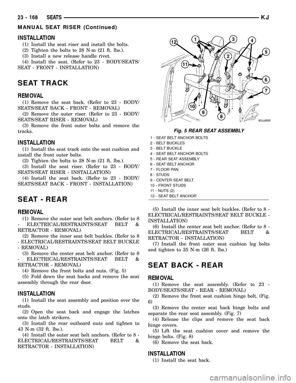
(4) Remove the front bolts and nuts. (Fig. 5)
(5) Fold down the seat backs and remove the seat
assembly through the rear door.
INSTALLATION
(1) Install the seat assembly and position over the
studs.
(2) Open the seat back and engage the latches
onto the latch strikers.
(3) Install the rear outboard nuts and tighten to
43 N´m (32 ft. lbs.).
(4) Install the outer seat belt anchors. (Refer to 8 -
ELECTRICAL/RESTRAINTS/SEAT BELT &
RETRACTOR - INSTALLATION)(5) Install the inner seat belt buckles. (Refer to 8 -
ELECTRICAL/RESTRAINTS/SEAT BELT BUCKLE -
INSTALLATION)
(6) Install the center seat belt anchor. (Refer to 8 -
ELECTRICAL/RESTRAINTS/SEAT BELT &
RETRACTOR - INSTALLATION)
(7) Install the front outer seat cushion leg bolts
and tighten to 35 N´m (26 ft. lbs.)
SEAT BACK - REAR
REMOVAL
(1) Remove the seat assembly. (Refer to 23 -
BODY/SEATS/SEAT - REAR - REMOVAL)
(2) Remove the front seat cushion hinge bolt. (Fig.
6)
(3) Remove the center seat back hinge bolts and
separate the rear seat assembly. (Fig. 7)
(4) Release the clips and remove the seat back
hinge covers.
(5) Lift the seat cushion cover and remove the
hinge bolts. (Fig. 8)
(6) Remove the seat back.
INSTALLATION
(1) Install the seat back.
Fig. 5 REAR SEAT ASSEMBLY
1 - SEAT BELT ANCHOR BOLTS
2 - BELT BUCKLES
3 - BELT BUCKLE
4 - SEAT BELT ANCHOR BOLTS
5 - REAR SEAT ASSEMBLY
6 - SEAT BELT ANCHOR
7 - FLOOR PAN
8 - STUDS
9 - CENTER SEAT BELT
10 - FRONT STUDS
11 - NUTS (2)
12 - SEAT BELT ANCHOR
23 - 168 SEATSKJ
MANUAL SEAT RISER (Continued)
Page 1636 of 1803
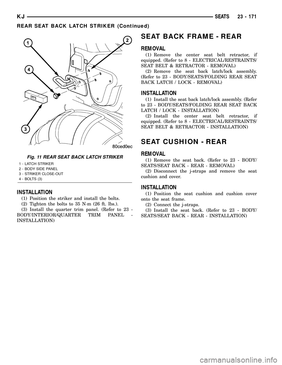
INSTALLATION
(1) Position the striker and install the bolts.
(2) Tighten the bolts to 35 N´m (26 ft. lbs.).
(3) Install the quarter trim panel. (Refer to 23 -
BODY/INTERIOR/QUARTER TRIM PANEL -
INSTALLATION)
SEAT BACK FRAME - REAR
REMOVAL
(1) Remove the center seat belt retractor, if
equipped. (Refer to 8 - ELECTRICAL/RESTRAINTS/
SEAT BELT & RETRACTOR - REMOVAL)
(2) Remove the seat back latch/lock assembly.
(Refer to 23 - BODY/SEATS/FOLDING REAR SEAT
BACK LATCH / LOCK - REMOVAL)
INSTALLATION
(1) Install the seat back latch/lock assembly. (Refer
to 23 - BODY/SEATS/FOLDING REAR SEAT BACK
LATCH / LOCK - INSTALLATION)
(2) Install the center seat belt retractor, if
equipped. (Refer to 8 - ELECTRICAL/RESTRAINTS/
SEAT BELT & RETRACTOR - INSTALLATION)
SEAT CUSHION - REAR
REMOVAL
(1) Remove the seat back. (Refer to 23 - BODY/
SEATS/SEAT BACK - REAR - REMOVAL)
(2) Disconnect the j-straps and remove the seat
cushion and cover.
INSTALLATION
(1) Position the seat cushion and cushion cover
onto the seat frame.
(2) Connect the j-straps.
(3) Install the seat back. (Refer to 23 - BODY/
SEATS/SEAT BACK - REAR - INSTALLATION)
Fig. 11 REAR SEAT BACK LATCH STRIKER
1 - LATCH STRIKER
2 - BODY SIDE PANEL
3 - STRIKER CLOSE-OUT
4 - BOLTS (3)
KJSEATS 23 - 171
REAR SEAT BACK LATCH STRIKER (Continued)
Page 1640 of 1803
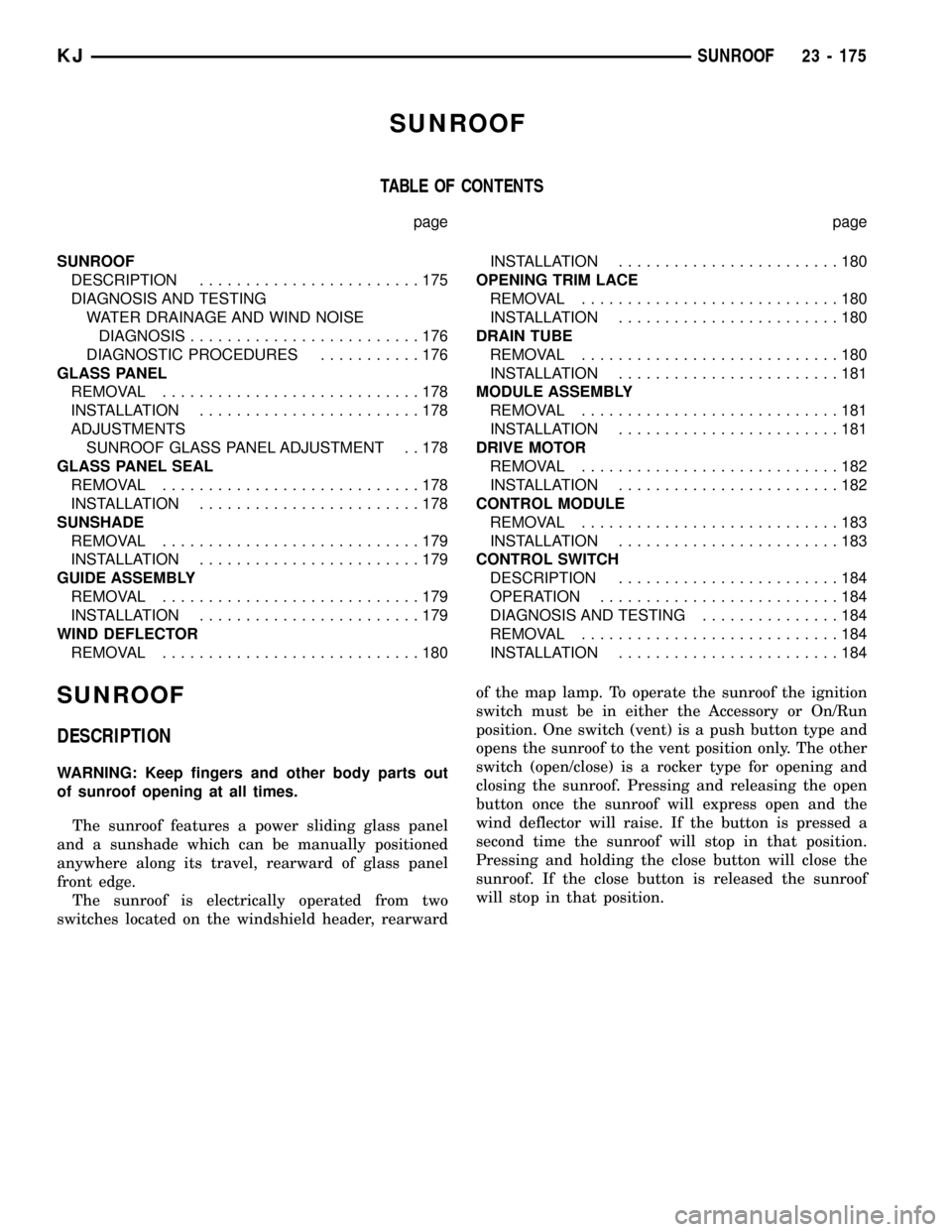
SUNROOF
TABLE OF CONTENTS
page page
SUNROOF
DESCRIPTION........................175
DIAGNOSIS AND TESTING
WATER DRAINAGE AND WIND NOISE
DIAGNOSIS.........................176
DIAGNOSTIC PROCEDURES...........176
GLASS PANEL
REMOVAL............................178
INSTALLATION........................178
ADJUSTMENTS
SUNROOF GLASS PANEL ADJUSTMENT . . 178
GLASS PANEL SEAL
REMOVAL............................178
INSTALLATION........................178
SUNSHADE
REMOVAL............................179
INSTALLATION........................179
GUIDE ASSEMBLY
REMOVAL............................179
INSTALLATION........................179
WIND DEFLECTOR
REMOVAL............................180INSTALLATION........................180
OPENING TRIM LACE
REMOVAL............................180
INSTALLATION........................180
DRAIN TUBE
REMOVAL............................180
INSTALLATION........................181
MODULE ASSEMBLY
REMOVAL............................181
INSTALLATION........................181
DRIVE MOTOR
REMOVAL............................182
INSTALLATION........................182
CONTROL MODULE
REMOVAL............................183
INSTALLATION........................183
CONTROL SWITCH
DESCRIPTION........................184
OPERATION..........................184
DIAGNOSIS AND TESTING...............184
REMOVAL............................184
INSTALLATION........................184
SUNROOF
DESCRIPTION
WARNING: Keep fingers and other body parts out
of sunroof opening at all times.
The sunroof features a power sliding glass panel
and a sunshade which can be manually positioned
anywhere along its travel, rearward of glass panel
front edge.
The sunroof is electrically operated from two
switches located on the windshield header, rearwardof the map lamp. To operate the sunroof the ignition
switch must be in either the Accessory or On/Run
position. One switch (vent) is a push button type and
opens the sunroof to the vent position only. The other
switch (open/close) is a rocker type for opening and
closing the sunroof. Pressing and releasing the open
button once the sunroof will express open and the
wind deflector will raise. If the button is pressed a
second time the sunroof will stop in that position.
Pressing and holding the close button will close the
sunroof. If the close button is released the sunroof
will stop in that position.
KJSUNROOF 23 - 175
Page 1641 of 1803
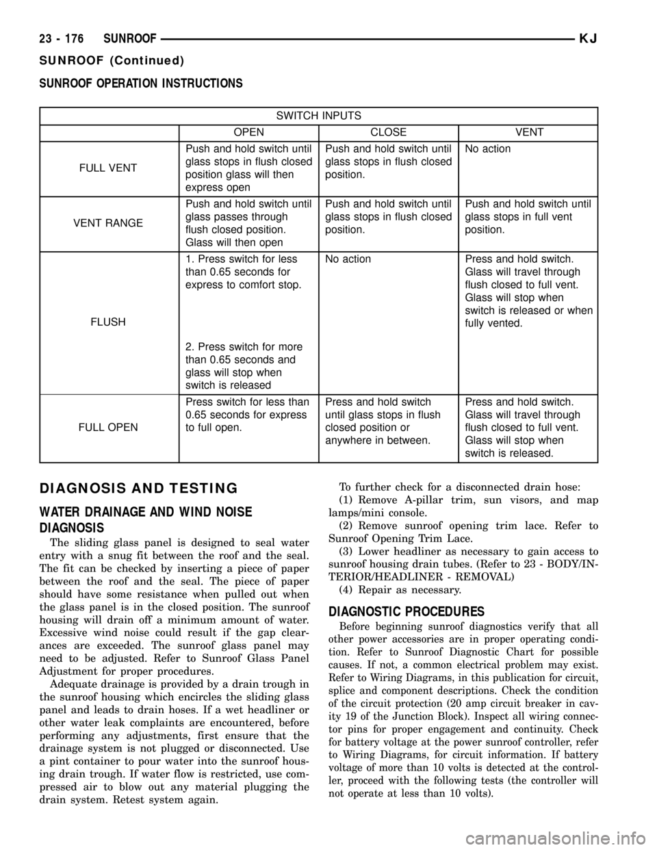
SUNROOF OPERATION INSTRUCTIONS
SWITCH INPUTS
OPEN CLOSE VENT
FULL VENTPush and hold switch until
glass stops in flush closed
position glass will then
express openPush and hold switch until
glass stops in flush closed
position.No action
VENT RANGEPush and hold switch until
glass passes through
flush closed position.
Glass will then openPush and hold switch until
glass stops in flush closed
position.Push and hold switch until
glass stops in full vent
position.
FLUSH1. Press switch for less
than 0.65 seconds for
express to comfort stop.No action Press and hold switch.
Glass will travel through
flush closed to full vent.
Glass will stop when
switch is released or when
fully vented.
2. Press switch for more
than 0.65 seconds and
glass will stop when
switch is released
FULL OPENPress switch for less than
0.65 seconds for express
to full open.Press and hold switch
until glass stops in flush
closed position or
anywhere in between.Press and hold switch.
Glass will travel through
flush closed to full vent.
Glass will stop when
switch is released.
DIAGNOSIS AND TESTING
WATER DRAINAGE AND WIND NOISE
DIAGNOSIS
The sliding glass panel is designed to seal water
entry with a snug fit between the roof and the seal.
The fit can be checked by inserting a piece of paper
between the roof and the seal. The piece of paper
should have some resistance when pulled out when
the glass panel is in the closed position. The sunroof
housing will drain off a minimum amount of water.
Excessive wind noise could result if the gap clear-
ances are exceeded. The sunroof glass panel may
need to be adjusted. Refer to Sunroof Glass Panel
Adjustment for proper procedures.
Adequate drainage is provided by a drain trough in
the sunroof housing which encircles the sliding glass
panel and leads to drain hoses. If a wet headliner or
other water leak complaints are encountered, before
performing any adjustments, first ensure that the
drainage system is not plugged or disconnected. Use
a pint container to pour water into the sunroof hous-
ing drain trough. If water flow is restricted, use com-
pressed air to blow out any material plugging the
drain system. Retest system again.To further check for a disconnected drain hose:
(1) Remove A-pillar trim, sun visors, and map
lamps/mini console.
(2) Remove sunroof opening trim lace. Refer to
Sunroof Opening Trim Lace.
(3) Lower headliner as necessary to gain access to
sunroof housing drain tubes. (Refer to 23 - BODY/IN-
TERIOR/HEADLINER - REMOVAL)
(4) Repair as necessary.
DIAGNOSTIC PROCEDURES
Before beginning sunroof diagnostics verify that all
other power accessories are in proper operating condi-
tion. Refer to Sunroof Diagnostic Chart for possible
causes. If not, a common electrical problem may exist.
Refer to Wiring Diagrams, in this publication for circuit,
splice and component descriptions. Check the condition
of the circuit protection (20 amp circuit breaker in cav-
ity 19 of the Junction Block). Inspect all wiring connec-
tor pins for proper engagement and continuity. Check
for battery voltage at the power sunroof controller, refer
to Wiring Diagrams, for circuit information. If battery
voltage of more than 10 volts is detected at the control-
ler, proceed with the following tests (the controller will
not operate at less than 10 volts).
23 - 176 SUNROOFKJ
SUNROOF (Continued)
Page 1642 of 1803
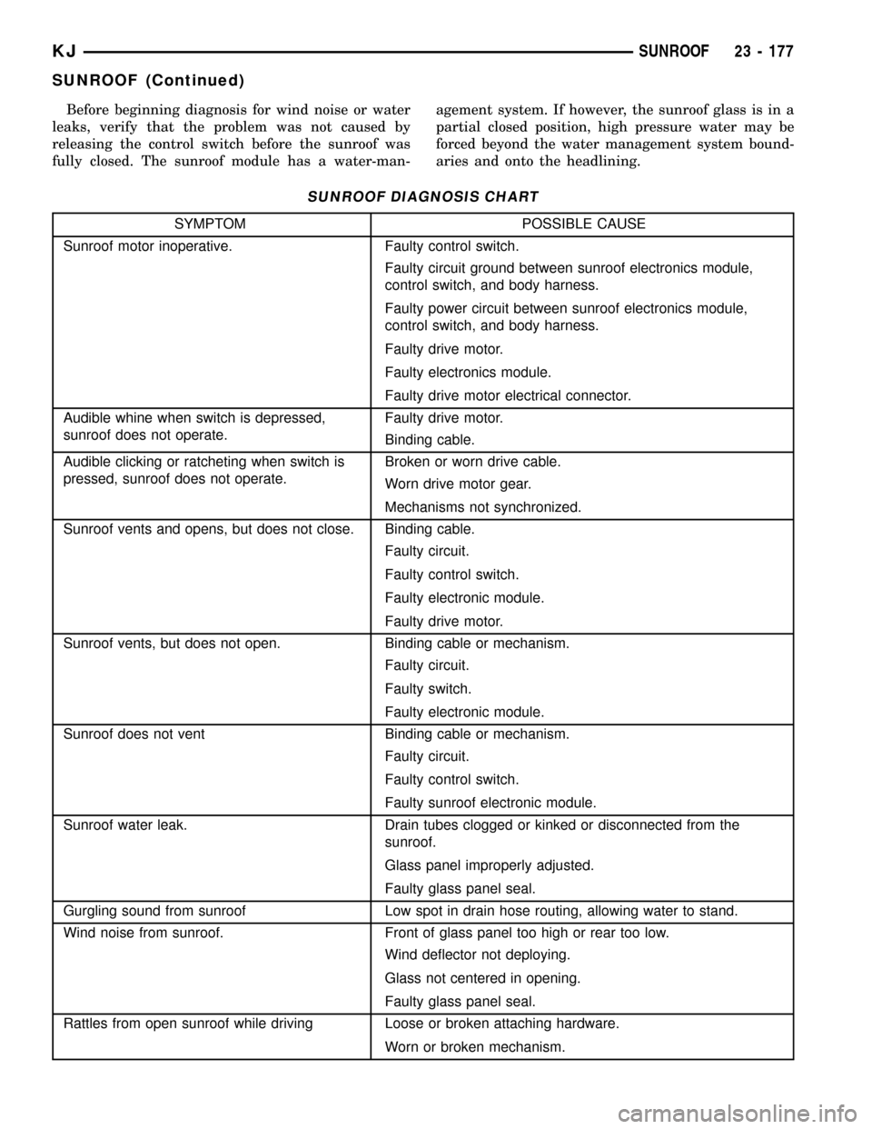
Before beginning diagnosis for wind noise or water
leaks, verify that the problem was not caused by
releasing the control switch before the sunroof was
fully closed. The sunroof module has a water-man-agement system. If however, the sunroof glass is in a
partial closed position, high pressure water may be
forced beyond the water management system bound-
aries and onto the headlining.
SUNROOF DIAGNOSIS CHART
SYMPTOM POSSIBLE CAUSE
Sunroof motor inoperative. Faulty control switch.
Faulty circuit ground between sunroof electronics module,
control switch, and body harness.
Faulty power circuit between sunroof electronics module,
control switch, and body harness.
Faulty drive motor.
Faulty electronics module.
Faulty drive motor electrical connector.
Audible whine when switch is depressed,
sunroof does not operate.Faulty drive motor.
Binding cable.
Audible clicking or ratcheting when switch is
pressed, sunroof does not operate.Broken or worn drive cable.
Worn drive motor gear.
Mechanisms not synchronized.
Sunroof vents and opens, but does not close. Binding cable.
Faulty circuit.
Faulty control switch.
Faulty electronic module.
Faulty drive motor.
Sunroof vents, but does not open. Binding cable or mechanism.
Faulty circuit.
Faulty switch.
Faulty electronic module.
Sunroof does not vent Binding cable or mechanism.
Faulty circuit.
Faulty control switch.
Faulty sunroof electronic module.
Sunroof water leak. Drain tubes clogged or kinked or disconnected from the
sunroof.
Glass panel improperly adjusted.
Faulty glass panel seal.
Gurgling sound from sunroof Low spot in drain hose routing, allowing water to stand.
Wind noise from sunroof. Front of glass panel too high or rear too low.
Wind deflector not deploying.
Glass not centered in opening.
Faulty glass panel seal.
Rattles from open sunroof while driving Loose or broken attaching hardware.
Worn or broken mechanism.
KJSUNROOF 23 - 177
SUNROOF (Continued)