2002 JEEP LIBERTY replace head gasket
[x] Cancel search: replace head gasketPage 1326 of 1803

(2) Insufficient running time after rebuilding cylin-
der head. Low speed running up to 1 hour may be
required.
(3) During this time, turn engine off and let set for
a few minutes before restarting. Repeat this several
times after engine has reached normal operating
temperature.
(4) Low oil pressure.
(5) The oil restrictor (integral to the head gasket)
in the vertical oil passage to the cylinder head is
plugged with debris.
(6) Air ingested into oil due to broken or cracked
oil pump pick up.
(7) Worn valve guides.
(8) Rocker arm ears contacting valve spring
retainer.
(9) Rocker arm loose, adjuster stuck or at maxi-
mum extension and still leaves lash in the system.
(10) Faulty lash adjuster.
a. Check lash adjusters for sponginess while
installed in cylinder head. Depress part of rocker
arm over adjuster. Normal adjusters should feel very
firm. Spongy adjusters can be bottomed out easily.
b. Remove suspected lash adjusters, and replace as
necessary.
REMOVAL
NOTE: This procedure is for in-vehicle service with
camshafts installed.
(1) Remove cylinder head cover. (Refer to 9 -
ENGINE/CYLINDER HEAD/CYLINDER HEAD
COVER(S) - REMOVAL)
(2) Remove the camshafts (Refer to 9 - ENGINE/
CYLINDER HEAD/CAMSHAFT(S) - REMOVAL).
(3) Remove rocker arm. (Refer to 9 - ENGINE/
CYLINDER HEAD/ROCKER ARMS - REMOVAL)
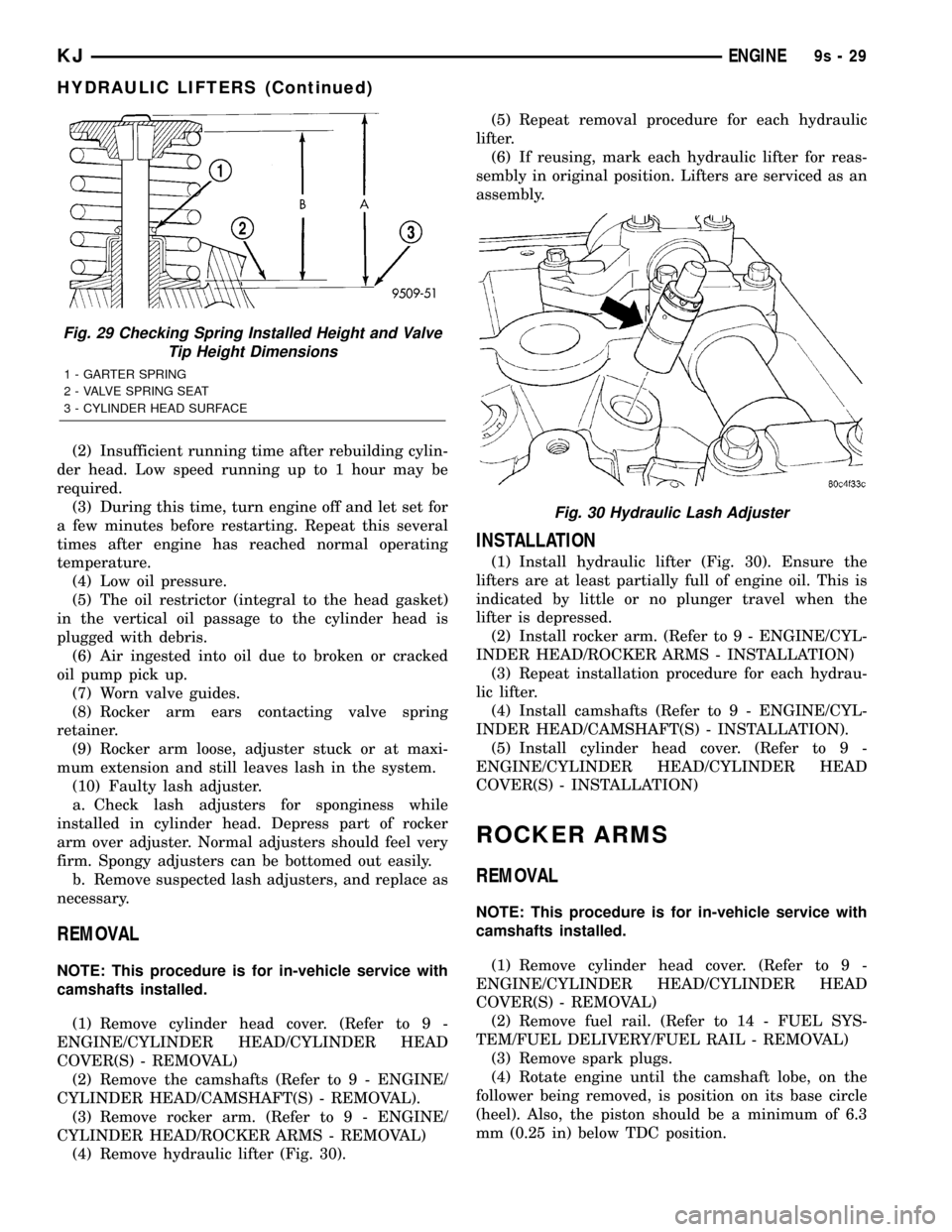
(4) Remove hydraulic lifter (Fig. 30).(5) Repeat removal procedure for each hydraulic
lifter.
(6) If reusing, mark each hydraulic lifter for reas-
sembly in original position. Lifters are serviced as an
assembly.
INSTALLATION
(1) Install hydraulic lifter (Fig. 30). Ensure the
lifters are at least partially full of engine oil. This is
indicated by little or no plunger travel when the
lifter is depressed.
(2) Install rocker arm. (Refer to 9 - ENGINE/CYL-
INDER HEAD/ROCKER ARMS - INSTALLATION)
(3) Repeat installation procedure for each hydrau-
lic lifter.
(4) Install camshafts (Refer to 9 - ENGINE/CYL-
INDER HEAD/CAMSHAFT(S) - INSTALLATION).
(5) Install cylinder head cover. (Refer to 9 -
ENGINE/CYLINDER HEAD/CYLINDER HEAD
COVER(S) - INSTALLATION)
ROCKER ARMS
REMOVAL
NOTE: This procedure is for in-vehicle service with
camshafts installed.
(1) Remove cylinder head cover. (Refer to 9 -
ENGINE/CYLINDER HEAD/CYLINDER HEAD
COVER(S) - REMOVAL)
(2) Remove fuel rail. (Refer to 14 - FUEL SYS-
TEM/FUEL DELIVERY/FUEL RAIL - REMOVAL)
(3) Remove spark plugs.
(4) Rotate engine until the camshaft lobe, on the
follower being removed, is position on its base circle
(heel). Also, the piston should be a minimum of 6.3
mm (0.25 in) below TDC position.
Fig. 29 Checking Spring Installed Height and Valve
Tip Height Dimensions
1 - GARTER SPRING
2 - VALVE SPRING SEAT
3 - CYLINDER HEAD SURFACE
Fig. 30 Hydraulic Lash Adjuster
KJENGINE9s-29
HYDRAULIC LIFTERS (Continued)
Page 1350 of 1803

EXHAUST MANIFOLD
DESCRIPTION
The exhaust manifold is made of Hi-Silicone Moly
nodular cast iron for strength and high tempera-
tures. The manifold attaches to the cylinder head.
OPERATION
The exhaust manifold collects the exhaust gasses
exiting the combustion chambers. Then it channels
the exhaust gasses to the exhaust pipe attached to
the manifold.
REMOVAL
(1) Raise vehicle and disconnect exhaust pipe from
the exhaust manifold.
(2) Lower the vehicle.
(3) Disconnect upstream oxygen sensor connector
at the rear of exhaust manifold.
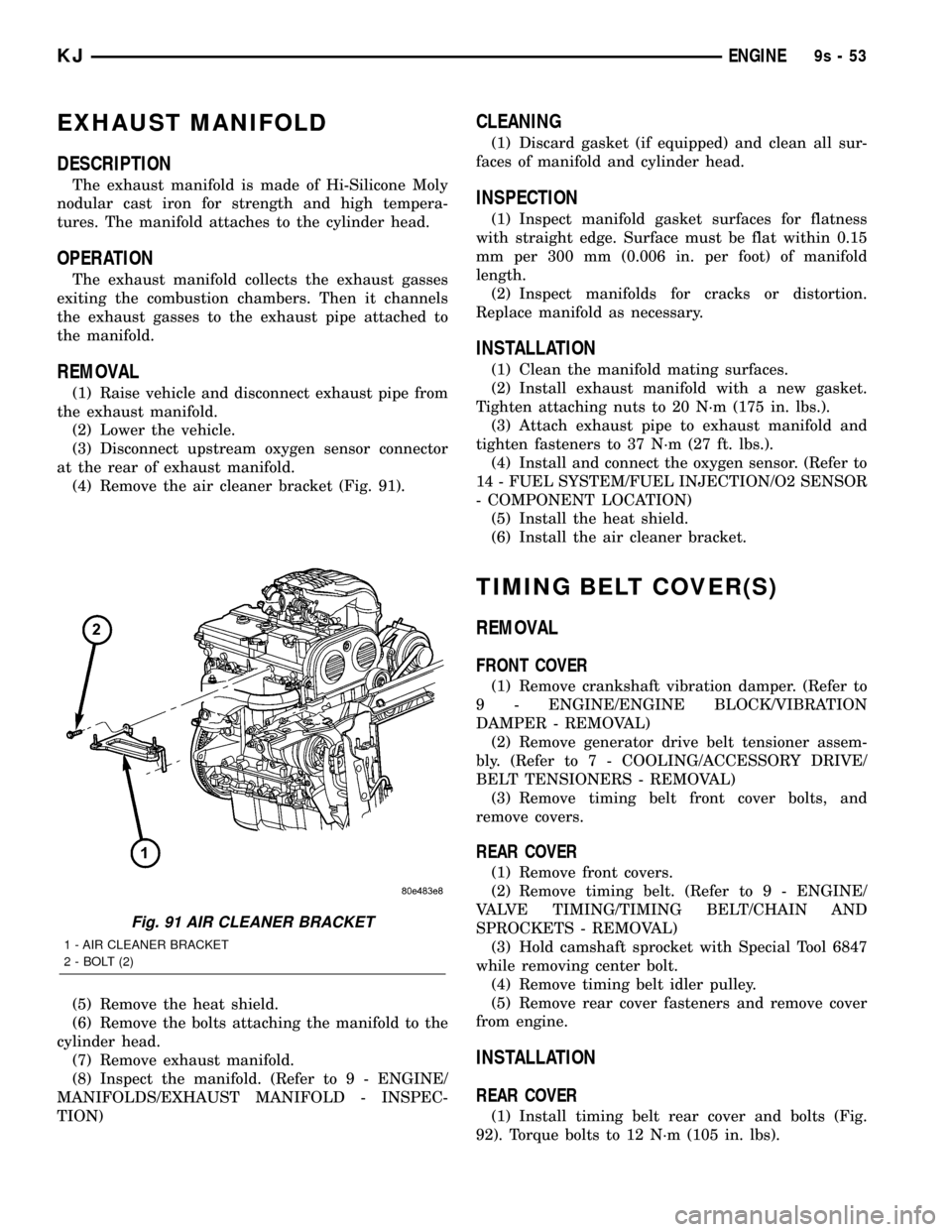
(4) Remove the air cleaner bracket (Fig. 91).
(5) Remove the heat shield.
(6) Remove the bolts attaching the manifold to the
cylinder head.
(7) Remove exhaust manifold.
(8) Inspect the manifold. (Refer to 9 - ENGINE/
MANIFOLDS/EXHAUST MANIFOLD - INSPEC-
TION)
CLEANING
(1) Discard gasket (if equipped) and clean all sur-
faces of manifold and cylinder head.
INSPECTION
(1) Inspect manifold gasket surfaces for flatness
with straight edge. Surface must be flat within 0.15
mm per 300 mm (0.006 in. per foot) of manifold
length.
(2) Inspect manifolds for cracks or distortion.
Replace manifold as necessary.
INSTALLATION
(1) Clean the manifold mating surfaces.
(2) Install exhaust manifold with a new gasket.
Tighten attaching nuts to 20 N´m (175 in. lbs.).
(3) Attach exhaust pipe to exhaust manifold and
tighten fasteners to 37 N´m (27 ft. lbs.).
(4) Install and connect the oxygen sensor. (Refer to
14 - FUEL SYSTEM/FUEL INJECTION/O2 SENSOR
- COMPONENT LOCATION)
(5) Install the heat shield.
(6) Install the air cleaner bracket.
TIMING BELT COVER(S)
REMOVAL
FRONT COVER
(1) Remove crankshaft vibration damper. (Refer to
9 - ENGINE/ENGINE BLOCK/VIBRATION
DAMPER - REMOVAL)
(2) Remove generator drive belt tensioner assem-
bly. (Refer to 7 - COOLING/ACCESSORY DRIVE/
BELT TENSIONERS - REMOVAL)
(3) Remove timing belt front cover bolts, and
remove covers.
REAR COVER
(1) Remove front covers.
(2) Remove timing belt. (Refer to 9 - ENGINE/
VALVE TIMING/TIMING BELT/CHAIN AND
SPROCKETS - REMOVAL)
(3) Hold camshaft sprocket with Special Tool 6847
while removing center bolt.
(4) Remove timing belt idler pulley.
(5) Remove rear cover fasteners and remove cover
from engine.
INSTALLATION
REAR COVER
(1) Install timing belt rear cover and bolts (Fig.
92). Torque bolts to 12 N´m (105 in. lbs).
Fig. 91 AIR CLEANER BRACKET
1 - AIR CLEANER BRACKET
2 - BOLT (2)
KJENGINE9s-53
Page 1691 of 1803

In addition, the flexible hose refrigerant lines should
be routed so they are at least 80 millimeters (3
inches) from an exhaust manifold.
WARNING
SERVICE WARNINGS
WARNING: THE AIR CONDITIONING SYSTEM CON-
TAINS REFRIGERANT UNDER HIGH PRESSURE.
SEVERE PERSONAL INJURY MAY RESULT FROM
IMPROPER SERVICE PROCEDURES. REPAIRS
SHOULD ONLY BE PERFORMED BY QUALIFIED SER-
VICE PERSONNEL.
AVOID BREATHING THE REFRIGERANT AND REFRIG-
ERANT OIL VAPOR OR MIST. EXPOSURE MAY IRRI-
TATE THE EYES, NOSE, AND/OR THROAT. WEAR EYE
PROTECTION WHEN SERVICING THE AIR CONDITION-
ING REFRIGERANT SYSTEM. SERIOUS EYE INJURY
CAN RESULT FROM DIRECT CONTACT WITH THE
REFRIGERANT. IF EYE CONTACT OCCURS, SEEK
MEDICAL ATTENTION IMMEDIATELY.
DO NOT EXPOSE THE REFRIGERANT TO OPEN
FLAME. POISONOUS GAS IS CREATED WHEN
REFRIGERANT IS BURNED. AN ELECTRONIC LEAK
DETECTOR IS RECOMMENDED.
IF ACCIDENTAL SYSTEM DISCHARGE OCCURS, VEN-
TILATE THE WORK AREA BEFORE RESUMING SER-
VICE. LARGE AMOUNTS OF REFRIGERANT
RELEASED IN A CLOSED WORK AREA WILL DIS-
PLACE THE OXYGEN AND CAUSE SUFFOCATION.
THE EVAPORATION RATE OF R-134a REFRIGERANT
AT AVERAGE TEMPERATURE AND ALTITUDE IS
EXTREMELY HIGH. AS A RESULT, ANYTHING THAT
COMES IN CONTACT WITH THE REFRIGERANT WILL
FREEZE. ALWAYS PROTECT THE SKIN OR DELICATE
OBJECTS FROM DIRECT CONTACT WITH THE
REFRIGERANT.
THE R-134a SERVICE EQUIPMENT OR THE VEHICLE
REFRIGERANT SYSTEM SHOULD NOT BE PRESSURE
TESTED OR LEAK TESTED WITH COMPRESSED AIR.
SOME MIXTURES OF AIR AND R-134a HAVE BEEN
SHOWN TO BE COMBUSTIBLE AT ELEVATED PRES-
SURES. THESE MIXTURES ARE POTENTIALLY DAN-
GEROUS, AND MAY RESULT IN FIRE OR EXPLOSION
CAUSING INJURY OR PROPERTY DAMAGE.
CAUTION
SERVICE CAUTIONS
CAUTION: Liquid refrigerant is corrosive to metal sur-
faces. Follow the operating instructions supplied with
the service equipment being used.Never add R-12 to a refrigerant system designed to
use R-134a. Damage to the system will result.
R-12 refrigerant oil must not be mixed with R-134a
refrigerant oil. They are not compatible.
Do not use R-12 equipment or parts on the R-134a
system. Damage to the system will result.
Do not overcharge the refrigerant system. This will
cause excessive compressor head pressure and can
cause noise and system failure.
Recover the refrigerant before opening any fitting or
connection. Open the fittings with caution, even after
the system has been discharged. Never open or
loosen a connection before recovering the refrigerant.
Do not remove the secondary retention clip from any
spring-lock coupler connection while the refrigerant
system is under pressure. Recover the refrigerant
before removing the secondary retention clip. Open
the fittings with caution, even after the system has
been discharged. Never open or loosen a connection
before recovering the refrigerant.
The refrigerant system must always be evacuated
before charging.
Do not open the refrigerant system or uncap a
replacement component until you are ready to service
the system. This will prevent contamination in the sys-
tem.
Before disconnecting a component, clean the outside
of the fittings thoroughly to prevent contamination
from entering the refrigerant system.
Immediately after disconnecting a component from the
refrigerant system, seal the open fittings with a cap or
plug.
Before connecting an open refrigerant fitting, always
install a new seal or gasket. Coat the fitting and seal
with clean refrigerant oil before connecting.
Do not remove the sealing caps from a replacement
component until it is to be installed.
When installing a refrigerant line, avoid sharp bends
that may restrict refrigerant flow. Position the refriger-
ant lines away from exhaust system components or
any sharp edges, which may damage the line.
Tighten refrigerant fittings only to the specified torque.
The aluminum fittings used in the refrigerant system
will not tolerate overtightening.
When disconnecting a refrigerant fitting, use a wrench
on both halves of the fitting. This will prevent twisting
of the refrigerant lines or tubes.
Refrigerant oil will absorb moisture from the atmo-
sphere if left uncapped. Do not open a container of
refrigerant oil until you are ready to use it. Replace the
cap on the oil container immediately after using. Store
refrigerant oil only in a clean, airtight, and moisture-
free container.
Keep service tools and the work area clean. Contami-
nation of the refrigerant system through careless work
habits must be avoided.
KJPLUMBING 24 - 39
PLUMBING (Continued)