2002 JEEP GRAND CHEROKEE check engine
[x] Cancel search: check enginePage 1426 of 2199
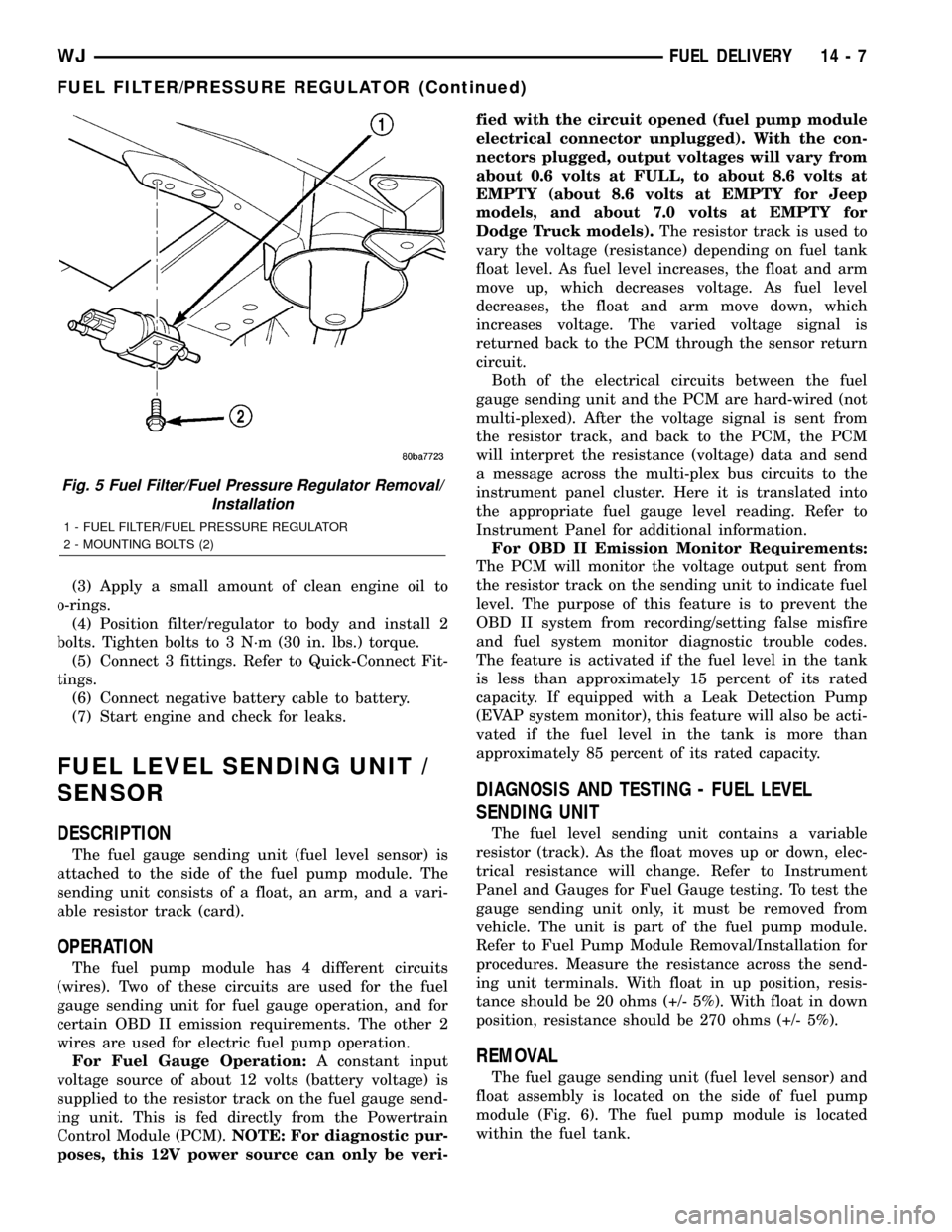
(3) Apply a small amount of clean engine oil to
o-rings.
(4) Position filter/regulator to body and install 2
bolts. Tighten bolts to 3 N´m (30 in. lbs.) torque.
(5) Connect 3 fittings. Refer to Quick-Connect Fit-
tings.
(6) Connect negative battery cable to battery.
(7) Start engine and check for leaks.
FUEL LEVEL SENDING UNIT /
SENSOR
DESCRIPTION
The fuel gauge sending unit (fuel level sensor) is
attached to the side of the fuel pump module. The
sending unit consists of a float, an arm, and a vari-
able resistor track (card).
OPERATION
The fuel pump module has 4 different circuits
(wires). Two of these circuits are used for the fuel
gauge sending unit for fuel gauge operation, and for
certain OBD II emission requirements. The other 2
wires are used for electric fuel pump operation.
For Fuel Gauge Operation:A constant input
voltage source of about 12 volts (battery voltage) is
supplied to the resistor track on the fuel gauge send-
ing unit. This is fed directly from the Powertrain
Control Module (PCM).NOTE: For diagnostic pur-
poses, this 12V power source can only be veri-fied with the circuit opened (fuel pump module
electrical connector unplugged). With the con-
nectors plugged, output voltages will vary from
about 0.6 volts at FULL, to about 8.6 volts at
EMPTY (about 8.6 volts at EMPTY for Jeep
models, and about 7.0 volts at EMPTY for
Dodge Truck models).The resistor track is used to
vary the voltage (resistance) depending on fuel tank
float level. As fuel level increases, the float and arm
move up, which decreases voltage. As fuel level
decreases, the float and arm move down, which
increases voltage. The varied voltage signal is
returned back to the PCM through the sensor return
circuit.
Both of the electrical circuits between the fuel
gauge sending unit and the PCM are hard-wired (not
multi-plexed). After the voltage signal is sent from
the resistor track, and back to the PCM, the PCM
will interpret the resistance (voltage) data and send
a message across the multi-plex bus circuits to the
instrument panel cluster. Here it is translated into
the appropriate fuel gauge level reading. Refer to
Instrument Panel for additional information.
For OBD II Emission Monitor Requirements:
The PCM will monitor the voltage output sent from
the resistor track on the sending unit to indicate fuel
level. The purpose of this feature is to prevent the
OBD II system from recording/setting false misfire
and fuel system monitor diagnostic trouble codes.
The feature is activated if the fuel level in the tank
is less than approximately 15 percent of its rated
capacity. If equipped with a Leak Detection Pump
(EVAP system monitor), this feature will also be acti-
vated if the fuel level in the tank is more than
approximately 85 percent of its rated capacity.
DIAGNOSIS AND TESTING - FUEL LEVEL
SENDING UNIT
The fuel level sending unit contains a variable
resistor (track). As the float moves up or down, elec-
trical resistance will change. Refer to Instrument
Panel and Gauges for Fuel Gauge testing. To test the
gauge sending unit only, it must be removed from
vehicle. The unit is part of the fuel pump module.
Refer to Fuel Pump Module Removal/Installation for
procedures. Measure the resistance across the send-
ing unit terminals. With float in up position, resis-
tance should be 20 ohms (+/- 5%). With float in down
position, resistance should be 270 ohms (+/- 5%).
REMOVAL
The fuel gauge sending unit (fuel level sensor) and
float assembly is located on the side of fuel pump
module (Fig. 6). The fuel pump module is located
within the fuel tank.
Fig. 5 Fuel Filter/Fuel Pressure Regulator Removal/
Installation
1 - FUEL FILTER/FUEL PRESSURE REGULATOR
2 - MOUNTING BOLTS (2)
WJFUEL DELIVERY 14 - 7
FUEL FILTER/PRESSURE REGULATOR (Continued)
Page 1428 of 2199
OPERATION
Voltage to operate the electric pump is supplied
through the fuel pump relay.
Fuel is drawn in through a filter at the bottom of
the module and pushed through the electric motor
gearset to the pump outlet.
Check Valve Operation:The pump outlet con-
tains a one-way check valve to prevent fuel flow back
into the tank and to maintain fuel supply line pres-
sure (engine warm) when pump is not operational. It
is also used to keep the fuel supply line full of gaso-
line when pump is not operational. After the vehicle
has cooled down, fuel pressure may drop to 0 psi
(cold fluid contracts), but liquid gasoline will remain
in fuel supply line between the check valve and fuel
injectors.Fuel pressure that has dropped to 0
psi on a cooled down vehicle (engine off) is a
normal condition.Refer to the Fuel Pressure Leak
Down Test for more information.
The electric fuel pump is not a separate, service-
able component.
DIAGNOSIS AND TESTING
DIAGNOSIS AND TESTING - FUEL PUMP
CAPACITY TEST
Before performing this test, verify fuel pump
pressure. Refer to Fuel Pump Pressure Test.
Use this test in conjunction with the Fuel Pres-
sure Leak Down Test.
(1) Release fuel system pressure. Refer to Fuel
Pressure Release Procedure.
(2) Disconnect fuel supply line at fuel rail. Refer to
Quick-Connect Fittings. Some engines may require
air cleaner housing removal before line disconnection.
(3) Obtain correct Fuel Line Pressure Test Adapter
Tool Hose. Tool number 6539 is used for 5/16º fuel
lines and tool number 6631 is used for 3/8º fuel lines.
(4) Connect correct Fuel Line Pressure Test
Adapter Tool Hose into disconnected fuel supply line.
Insert other end of Adaptor Tool Hose into a gradu-
ated container.
(5) Remove fuel fill cap.
(6) To activate fuel pump and pressurize system,
obtain DRBtscan tool and actuate ASD Fuel System
Test.
(7) A good fuel pump will deliver at least 1/4 liter
of fuel in 7 seconds. Do not operate fuel pump for
longer than 7 seconds with fuel line disconnected as
fuel pump module reservoir may run empty.
(a) If capacity is lower than specification, but
fuel pump can be heard operating through fuel fill
cap opening, check for a kinked/damaged fuel sup-
ply line somewhere between fuel rail and fuel
pump module.(b) If line is not kinked/damaged, and fuel pres-
sure is OK, but capacity is low, replace fuel filter/
fuel pressure regulator. The filter/regulator may be
serviced separately on certain applications. Refer
to Fuel Filter/Fuel Pressure Regulator Removal/In-
stallation for additional information.
(c) If both fuel pressure and capacity are low,
replace fuel pump module assembly. Refer to Fuel
Pump Module Removal/Installation.
DIAGNOSIS AND TESTING - FUEL PUMP
AMPERAGE TEST
This amperage (current draw) test is to be done in
conjunction with the Fuel Pump Pressure Test, Fuel
Pump Capacity Test and Fuel Pressure Leak Down
Test. Before performing the amperage test, be sure
the temperature of the fuel tank is above 50É F (10É
C).
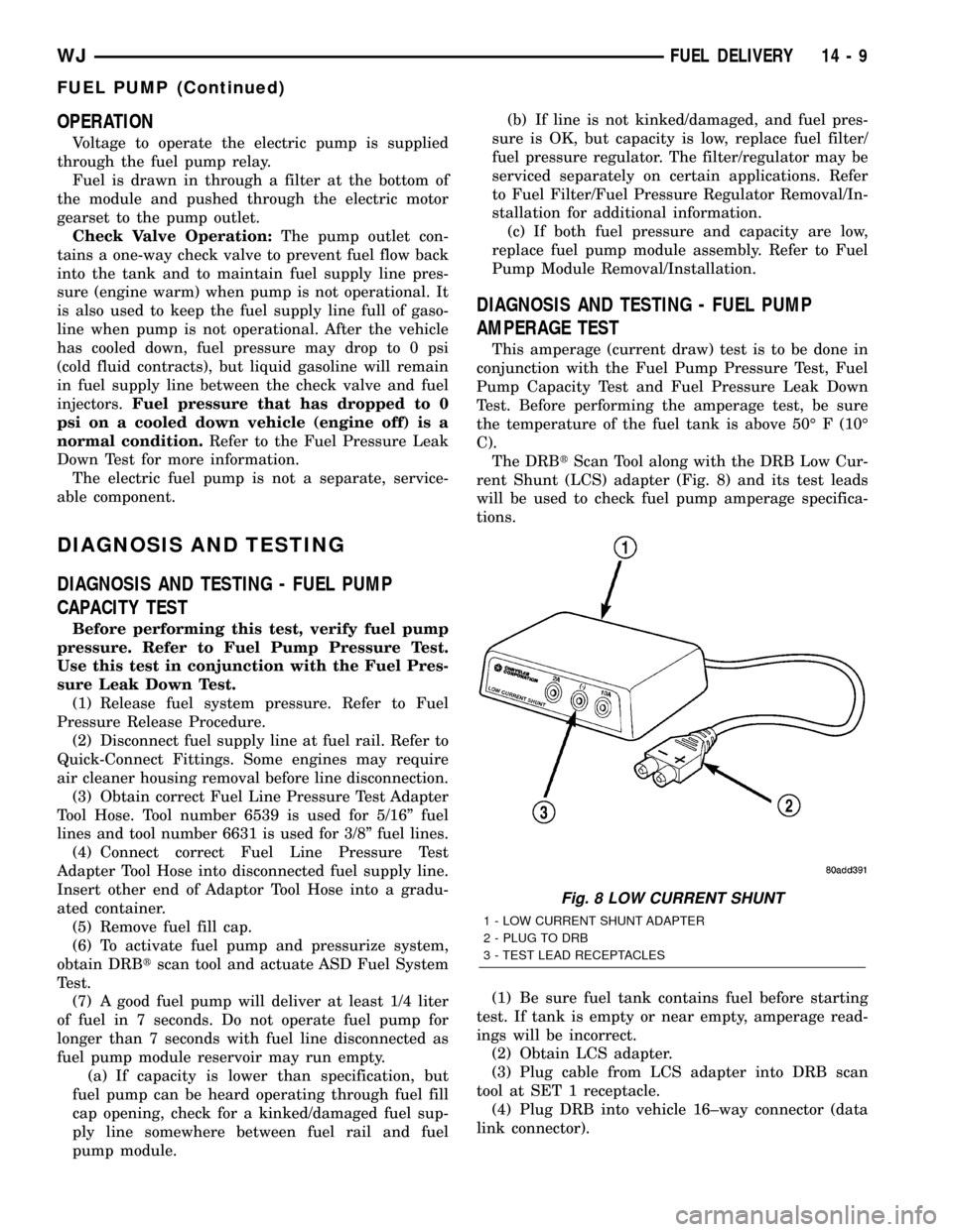
The DRBtScan Tool along with the DRB Low Cur-
rent Shunt (LCS) adapter (Fig. 8) and its test leads
will be used to check fuel pump amperage specifica-
tions.
(1) Be sure fuel tank contains fuel before starting
test. If tank is empty or near empty, amperage read-
ings will be incorrect.
(2) Obtain LCS adapter.
(3) Plug cable from LCS adapter into DRB scan
tool at SET 1 receptacle.
(4) Plug DRB into vehicle 16±way connector (data
link connector).
Fig. 8 LOW CURRENT SHUNT
1 - LOW CURRENT SHUNT ADAPTER
2 - PLUG TO DRB
3 - TEST LEAD RECEPTACLES
WJFUEL DELIVERY 14 - 9
FUEL PUMP (Continued)
Page 1430 of 2199
(19) Disconnect test leads from relay cavities
immediately after testing.
FUEL PUMP PRESSURE TEST
Use this test in conjunction with other fuel system
tests. Refer to the Fuel Pump Capacity Test, Fuel
Pressure Leak Down Test and Fuel Pump Amperage
Test.
Check Valve Operation:The electric fuel pump
outlet contains a one-way check valve to prevent fuel
flow back into the tank and to maintain fuel supply
line pressure (engine warm) when pump is not oper-
ational. It is also used to keep the fuel supply line
full of gasoline when pump is not operational. After
the vehicle has cooled down, fuel pressure may drop
to 0 psi (cold fluid contracts), but liquid gasoline will
remain in fuel supply line between the check valve
and fuel injectors.Fuel pressure that has
dropped to 0 psi on a cooled down vehicle
(engine off) is a normal condition.When the elec-
tric fuel pump is activated, fuel pressure should
immediately(1±2 seconds) rise to specification.
The fuel system is equipped with a combination
fuel filter/fuel pressure regulator. The fuel pressure
regulator is not controlled by engine vacuum.
WARNING: THE FUEL SYSTEM IS UNDER CON-
STANT FUEL PRESSURE EVEN WITH THE ENGINE
OFF. BEFORE DISCONNECTING FUEL LINE AT
FUEL RAIL, THIS PRESSURE MUST BE RELEASED.REFER TO THE FUEL SYSTEM PRESSURE
RELEASE PROCEDURE.
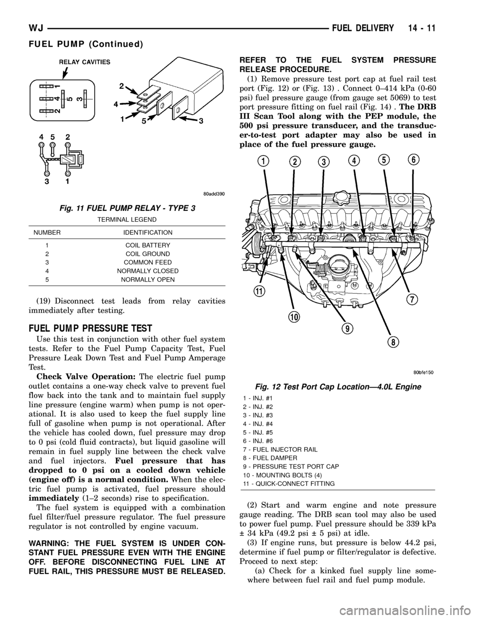
(1) Remove pressure test port cap at fuel rail test
port (Fig. 12) or (Fig. 13) . Connect 0±414 kPa (0-60
psi) fuel pressure gauge (from gauge set 5069) to test
port pressure fitting on fuel rail (Fig. 14) .The DRB
III Scan Tool along with the PEP module, the
500 psi pressure transducer, and the transduc-
er-to-test port adapter may also be used in
place of the fuel pressure gauge.
(2) Start and warm engine and note pressure
gauge reading. The DRB scan tool may also be used
to power fuel pump. Fuel pressure should be 339 kPa
34 kPa (49.2 psi 5 psi) at idle.
(3) If engine runs, but pressure is below 44.2 psi,
determine if fuel pump or filter/regulator is defective.
Proceed to next step:
(a) Check for a kinked fuel supply line some-
where between fuel rail and fuel pump module.
Fig. 11 FUEL PUMP RELAY - TYPE 3
TERMINAL LEGEND
NUMBER IDENTIFICATION
1 COIL BATTERY
2 COIL GROUND
3 COMMON FEED
4 NORMALLY CLOSED
5 NORMALLY OPEN
Fig. 12 Test Port Cap LocationÐ4.0L Engine
1 - INJ. #1
2 - INJ. #2
3 - INJ. #3
4 - INJ. #4
5 - INJ. #5
6 - INJ. #6
7 - FUEL INJECTOR RAIL
8 - FUEL DAMPER
9 - PRESSURE TEST PORT CAP
10 - MOUNTING BOLTS (4)
11 - QUICK-CONNECT FITTING
WJFUEL DELIVERY 14 - 11
FUEL PUMP (Continued)
Page 1432 of 2199
(e) Use DRB scan tool to power fuel pump. If
pressure is now within specifications, replace fuel
filter/fuel pressure regulator.
(f) If pressure is still low, replace fuel pump
module.
(4) If operating pressure is above 54.2 psi, electric
fuel pump is OK, but fuel pressure regulator is defec-
tive. Replace fuel filter/fuel pressure regulator.
(5) Install test port cap to fuel rail test port.
FUEL PUMP MODULE
DESCRIPTION
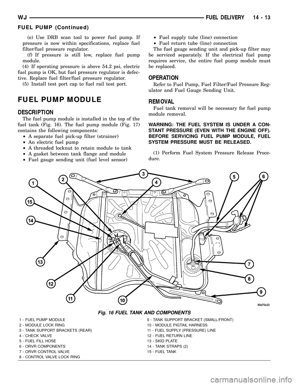
The fuel pump module is installed in the top of the
fuel tank (Fig. 16). The fuel pump module (Fig. 17)
contains the following components:
²A separate fuel pick-up filter (strainer)
²An electric fuel pump
²A threaded locknut to retain module to tank
²A gasket between tank flange and module
²Fuel gauge sending unit (fuel level sensor)²Fuel supply tube (line) connection
²Fuel return tube (line) connection
The fuel gauge sending unit and pick-up filter may
be serviced separately. If the electrical fuel pump
requires service, the entire fuel pump module must
be replaced.
OPERATION
Refer to Fuel Pump, Fuel Filter/Fuel Pressure Reg-
ulator and Fuel Gauge Sending Unit.
REMOVAL
Fuel tank removal will be necessary for fuel pump
module removal.
WARNING: THE FUEL SYSTEM IS UNDER A CON-
STANT PRESSURE (EVEN WITH THE ENGINE OFF).
BEFORE SERVICING FUEL PUMP MODULE, FUEL
SYSTEM PRESSURE MUST BE RELEASED.
(1) Perform Fuel System Pressure Release Proce-
dure.
Fig. 16 FUEL TANK AND COMPONENTS
1 - FUEL PUMP MODULE 9 - TANK SUPPORT BRACKET (SMALL/FRONT)
2 - MODULE LOCK RING 10 - MODULE PIGTAIL HARNESS
3 - TANK SUPPORT BRACKETS (REAR) 11 - FUEL SUPPLY (PRESSURE) LINE
4 - CHECK VALVE 12 - FUEL RETURN LINE
5 - FUEL FILL HOSE 13 - SKID PLATE
6 - ORVR COMPONENTS 14 - TANK STRAPS (2)
7 - ORVR CONTROL VALVE 15 - FUEL TANK
8 - CONTROL VALVE LOCK RING
WJFUEL DELIVERY 14 - 13
FUEL PUMP (Continued)
Page 1437 of 2199
(9) Disconnect speed control cable at throttle body
(if equipped). Refer to Speed Control Cable.
(10) Disconnect automatic transmission cable at
throttle body (if equipped).
(11) Remove cable routing bracket at intake mani-
fold.
(12) Clean dirt/debris from each fuel injector at
intake manifold.
(13) Remove fuel rail mounting nuts/bolts (Fig.
24).
(14) Remove fuel rail by gently rocking until all
fuel injectors have cleared machined holes at intake
manifold.
(15) If fuel injectors are to be removed, refer to
Fuel Injector Removal/Installation.
INSTALLATION
INSTALLATION - 4.7L
(1) If fuel injectors are to be installed, refer to Fuel
Injector Removal/Installation.
(2) Apply a small amount of engine oil to each fuel
injector o-ring. This will help in fuel rail installation.
(3) Position fuel rail/fuel injector assembly to
machined injector openings in cylinder head.
(4) Guide each injector into cylinder head. Be care-
ful not to tear injector o-rings.(5) Pushrightside of fuel rail down until fuel
injectors have bottomed on cylinder head shoulder.
Pushleftfuel rail down until injectors have bot-
tomed on cylinder head shoulder.
(6) Install 4 fuel rail mounting bolts and tighten to
27 N´m (20 ft. lbs.).
(7) Install ignition coils. Refer to Ignition Coil
Removal/Installation.
(8) Connect electrical connectors to throttle body.
(9) Connect electrical connectors to MAP and IAT
sensors.
(10) Connect electrical connectors at all fuel injec-
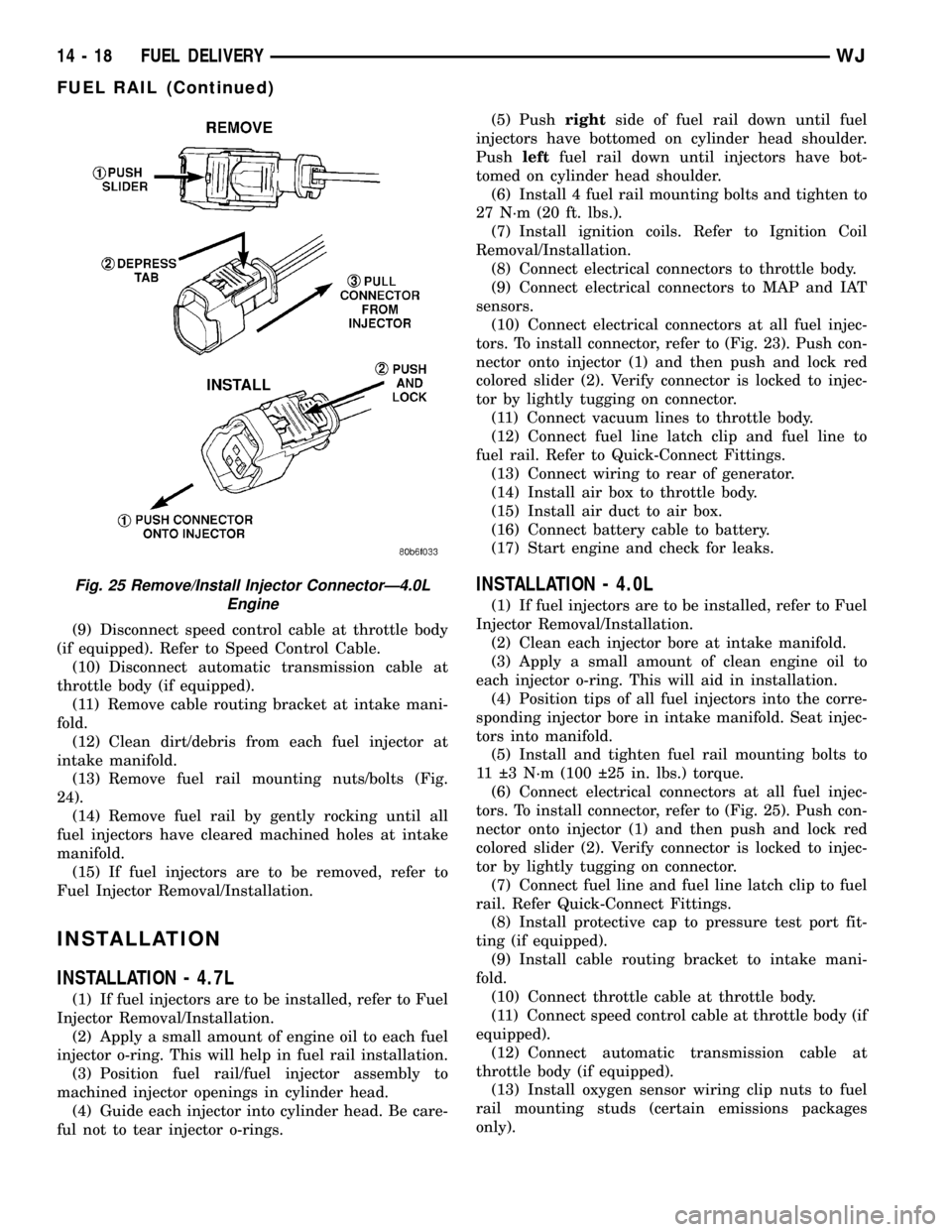
tors. To install connector, refer to (Fig. 23). Push con-
nector onto injector (1) and then push and lock red
colored slider (2). Verify connector is locked to injec-
tor by lightly tugging on connector.
(11) Connect vacuum lines to throttle body.
(12) Connect fuel line latch clip and fuel line to
fuel rail. Refer to Quick-Connect Fittings.
(13) Connect wiring to rear of generator.
(14) Install air box to throttle body.
(15) Install air duct to air box.
(16) Connect battery cable to battery.
(17) Start engine and check for leaks.
INSTALLATION - 4.0L
(1) If fuel injectors are to be installed, refer to Fuel
Injector Removal/Installation.
(2) Clean each injector bore at intake manifold.
(3) Apply a small amount of clean engine oil to
each injector o-ring. This will aid in installation.
(4) Position tips of all fuel injectors into the corre-
sponding injector bore in intake manifold. Seat injec-
tors into manifold.
(5) Install and tighten fuel rail mounting bolts to
11 3 N´m (100 25 in. lbs.) torque.
(6) Connect electrical connectors at all fuel injec-
tors. To install connector, refer to (Fig. 25). Push con-
nector onto injector (1) and then push and lock red
colored slider (2). Verify connector is locked to injec-
tor by lightly tugging on connector.
(7) Connect fuel line and fuel line latch clip to fuel
rail. Refer Quick-Connect Fittings.
(8) Install protective cap to pressure test port fit-
ting (if equipped).
(9) Install cable routing bracket to intake mani-
fold.
(10) Connect throttle cable at throttle body.
(11) Connect speed control cable at throttle body (if
equipped).
(12) Connect automatic transmission cable at
throttle body (if equipped).
(13) Install oxygen sensor wiring clip nuts to fuel
rail mounting studs (certain emissions packages
only).
Fig. 25 Remove/Install Injector ConnectorÐ4.0L
Engine
14 - 18 FUEL DELIVERYWJ
FUEL RAIL (Continued)
Page 1438 of 2199

(14) Install air tube (or duct) at top of throttle
body.
(15) Install fuel tank cap.
(16) Connect negative battery cable to battery.
(17) Start engine and check for fuel leaks.
FUEL TANK
DESCRIPTION
The fuel tank is constructed of a plastic material.
Its main functions are for fuel storage and for place-
ment of the fuel pump module and certain ORVR
components.
OPERATION
All models pass a full 360 degree rollover test
without fuel leakage. To accomplish this, fuel and
vapor flow controls are required for all fuel tank con-
nections.
A fuel tank check valve(s) is mounted into the top
of the fuel tank (or pump module). Refer to Fuel
Tank Check Valve for additional information.
An evaporation control system is connected to the
check valve(s) to reduce emissions of fuel vapors into
the atmosphere. When fuel evaporates from the fuel
tank, vapors pass through vent hoses or tubes to a
charcoal canister where they are temporarily held.
When the engine is running, the vapors are drawn
into the intake manifold. Certain models are also
equipped with a self-diagnosing system using a Leak
Detection Pump (LDP). Refer to Emission Control
System for additional information.
Refer to ORVR for On-Board Refueling Vapor
Recovery system information.
REMOVAL
WARNING: THE FUEL SYSTEM IS UNDER CON-
STANT FUEL PRESSURE EVEN WITH ENGINE OFF.
PRESSURE MUST BE RELEASED BEFORE SERVIC-
ING FUEL TANK.
Two different procedures may be used to drain fuel
tank (through ORVR control valve opening at top of
fuel tank, or using DRB scan tool). The quickest is
draining through ORVR control valve opening at top
of fuel tank (Fig. 26).
As an alternative procedure, the electric fuel pump
may be activated allowing tank to be drained at fuel
rail connection. Refer to DRB scan tool for fuel pump
activation procedures. Before disconnecting fuel line
at fuel rail, release fuel pressure. Refer to the Fuel
System Pressure Release Procedure for procedures.
Attach end of Special Adapter Hose Tool number
6539 at fuel rail disconnection. Position opposite end
of 6539 to an approved gasoline draining station.Activate fuel pump with DRB and drain tank until
empty.
If electric fuel pump is not operating, tankMUST
be drained through ORVR control valve opening at
top of fuel tank (Fig. 26).
(1) Release fuel system pressure. Refer to Fuel
System Pressure Release Procedure.
(2) Disconnect negative battery cable at battery.
(3) Raise and support vehicle.
(4) Remove left rear wheel/tire.
CAUTION: HANDLE EVAP, LDP AND ORVR VAPOR /
VACUUM LINES VERY CAREFULLY. THESE LINES
AND HOSES MUST BE FIRMLY CONNECTED.
CHECK THE VAPOR/VACUUM LINES AT THE LDP,
LDP FILTER, EVAP CANISTER, EVAP CANISTER
PURGE SOLENOID AND ORVR COMPONENTS FOR
DAMAGE OR LEAKS. IF A LEAK IS PRESENT, A
DIAGNOSTIC TROUBLE CODE (DTC) MAY BE SET.
(5) Clean top of fuel tank at ORVR control valve
(Fig. 26) or (Fig. 27).
(6) Press release tab in direction of arrow in (Fig.
27) and remove ORVR control valve lock ring
(counter-clockwise). Lift up ORVR control slightly.
Using an approved gasoline draining station, drain
tank until empty through this opening.
(7) Remove stone shield behind left/rear wheel
(Fig. 28). Drill out plastic rivets for removal.
(8) Remove 3 LDP mounting bolts (Fig. 29).
(9) Remove support bracket brace bolt (Fig. 30).
(10) Loosen, but do not remove 2 support bracket
nuts at frame rail (Fig. 29).
(11) To separate and lower front section of two-
piece support bracket, remove 3 attaching bolts on
bottom of support bracket (Fig. 30). While lowering
support bracket, disconnect LDP wiring clip (Fig. 31).
(12) Remove hose clamp (Fig. 32) and remove fuel
fill hose from fuel fill tube.
(13) Cut and discard tie wrap from axle vent hose
(Fig. 32).
(14) Disconnect fuel vent hose from fuel vent tube
(Fig. 32).
(15) Disconnect ORVR hose elbow (Fig. 33) at top
of EVAP canister.
(16) Place hydraulic jack to bottom of fuel tank.
(17) Remove fuel tank-to-rear bumper fascia clips
(Fig. 34).
(18) Remove fuel tank heat shield mounting bolts
(Fig. 35).
CAUTION: To protect fuel tank from exhaust heat,
shield must re-installed after tank installation.
WARNING: PLACE SHOP TOWEL AROUND FUEL
LINES TO CATCH ANY EXCESS FUEL.
WJFUEL DELIVERY 14 - 19
FUEL RAIL (Continued)
Page 1449 of 2199
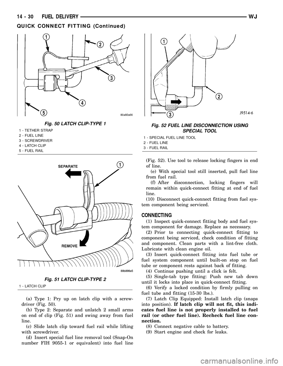
(a) Type 1: Pry up on latch clip with a screw-
driver (Fig. 50).
(b) Type 2: Separate and unlatch 2 small arms
on end of clip (Fig. 51) and swing away from fuel
line.
(c) Slide latch clip toward fuel rail while lifting
with screwdriver.
(d) Insert special fuel line removal tool (Snap-On
number FIH 9055-1 or equivalent) into fuel line(Fig. 52). Use tool to release locking fingers in end
of line.
(e) With special tool still inserted, pull fuel line
from fuel rail.
(f) After disconnection, locking fingers will
remain within quick-connect fitting at end of fuel
line.
(10) Disconnect quick-connect fitting from fuel sys-
tem component being serviced.
CONNECTING
(1) Inspect quick-connect fitting body and fuel sys-
tem component for damage. Replace as necessary.
(2) Prior to connecting quick-connect fitting to
component being serviced, check condition of fitting
and component. Clean parts with a lint-free cloth.
Lubricate with clean engine oil.
(3) Insert quick-connect fitting into fuel tube or
fuel system component until built-on stop on fuel
tube or component rests against back of fitting.
(4) Continue pushing until a click is felt.
(5) Single-tab type fitting: Push new tab down
until it locks into place in quick-connect fitting.
(6) Verify a locked condition by firmly pulling on
fuel tube and fitting (15-30 lbs.).
(7) Latch Clip Equipped: Install latch clip (snaps
into position).If latch clip will not fit, this indi-
cates fuel line is not properly installed to fuel
rail (or other fuel line). Recheck fuel line con-
nection.
(8) Connect negative cable to battery.
(9) Start engine and check for leaks.
Fig. 50 LATCH CLIP-TYPE 1
1 - TETHER STRAP
2 - FUEL LINE
3 - SCREWDRIVER
4 - LATCH CLIP
5 - FUEL RAIL
Fig. 51 LATCH CLIP-TYPE 2
1 - LATCH CLIP
Fig. 52 FUEL LINE DISCONNECTION USING
SPECIAL TOOL
1 - SPECIAL FUEL LINE TOOL
2 - FUEL LINE
3 - FUEL RAIL
14 - 30 FUEL DELIVERYWJ
QUICK CONNECT FITTING (Continued)
Page 1451 of 2199
FUEL INJECTION
DIAGNOSIS AND TESTING
VISUAL INSPECTION
A visual inspection for loose, disconnected or incor-
rectly routed wires, vacuum lines and hoses should
be made. This should be done before attempting to
diagnose or service the fuel injection system. A visual
check will help spot these faults and save unneces-
sary test and diagnostic time. A thorough visual
inspection will include the following checks:
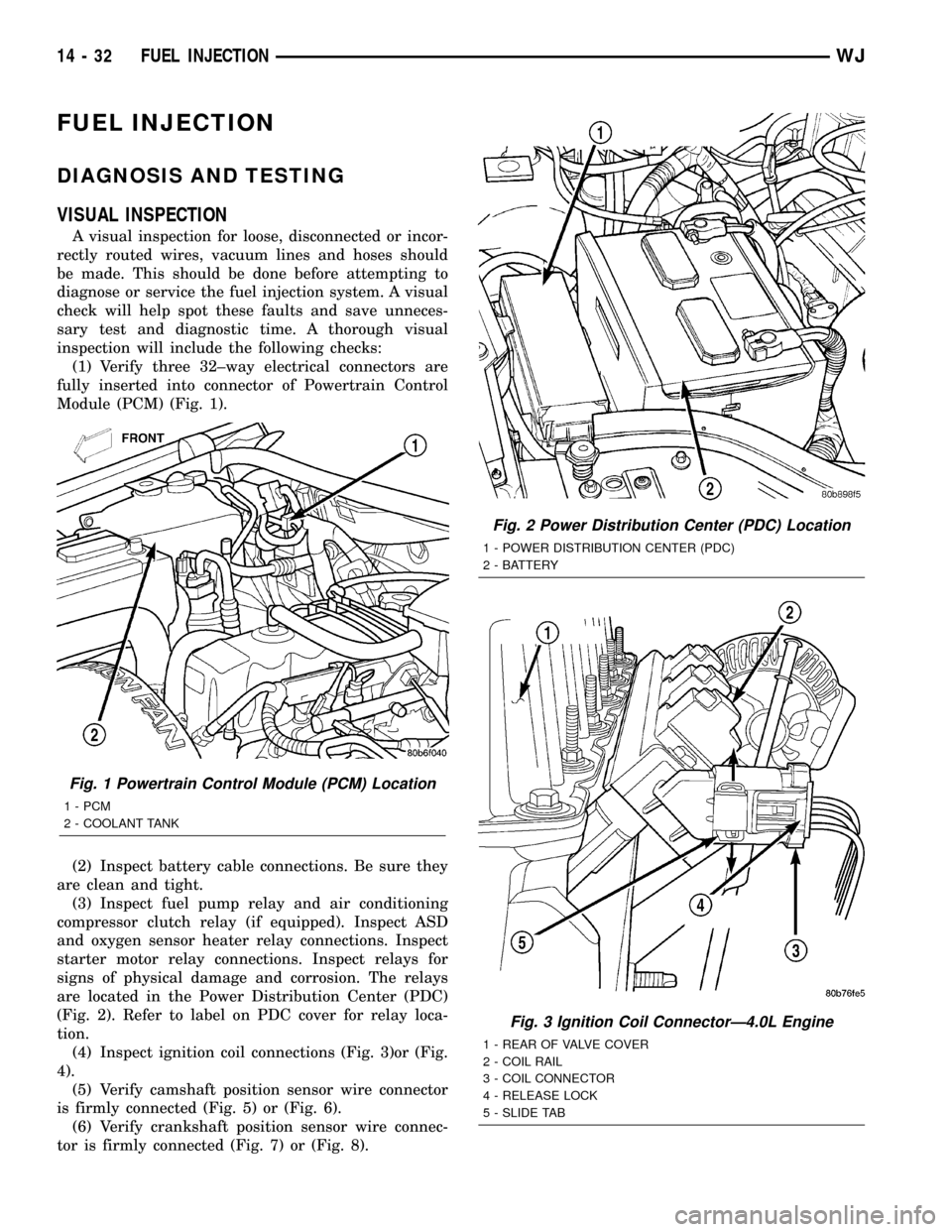
(1) Verify three 32±way electrical connectors are
fully inserted into connector of Powertrain Control
Module (PCM) (Fig. 1).
(2) Inspect battery cable connections. Be sure they
are clean and tight.
(3) Inspect fuel pump relay and air conditioning
compressor clutch relay (if equipped). Inspect ASD
and oxygen sensor heater relay connections. Inspect
starter motor relay connections. Inspect relays for
signs of physical damage and corrosion. The relays
are located in the Power Distribution Center (PDC)
(Fig. 2). Refer to label on PDC cover for relay loca-
tion.
(4) Inspect ignition coil connections (Fig. 3)or (Fig.
4).
(5) Verify camshaft position sensor wire connector
is firmly connected (Fig. 5) or (Fig. 6).
(6) Verify crankshaft position sensor wire connec-
tor is firmly connected (Fig. 7) or (Fig. 8).
Fig. 1 Powertrain Control Module (PCM) Location
1 - PCM
2 - COOLANT TANK
Fig. 2 Power Distribution Center (PDC) Location
1 - POWER DISTRIBUTION CENTER (PDC)
2 - BATTERY
Fig. 3 Ignition Coil ConnectorÐ4.0L Engine
1 - REAR OF VALVE COVER
2 - COIL RAIL
3 - COIL CONNECTOR
4 - RELEASE LOCK
5 - SLIDE TAB
14 - 32 FUEL INJECTIONWJ