2002 JEEP GRAND CHEROKEE check engine
[x] Cancel search: check enginePage 1384 of 2199
INSPECTION
(1) Inspect the exhaust manifold for cracks in the
mating surface and at every mounting bolt hole.
(2) Using a straight edge and a feeler gauge, check
the mating surface for warp and twist.
(3) Inspect the manifold to exhaust pipe mating
surface for cracks, gouges, or other damage that
would prevent sealing.
INSTALLATION
(1) Install exhaust manifold and gasket from below
engine compartment.
(2) Install lower exhaust manifold fasteners. DO
NOT tighten until all fasteners are in place.
(3) Lower vehicle and install upper exhaust mani-
fold fasteners. Tighten all manifold bolts starting at
center and working outward to 25 N´m (18 ft. lbs.).
CAUTION: Over tightening heat shield fasteners,
may cause shield to distort and/or crack.
(4) Install exhaust manifold heat shield. Tighten
fasteners to 8 N´m (72 in. lbs.), then loosen 45
degrees.
(5) Install starter and fasteners.
(6) Connect exhaust pipe to manifold.
(7) Connect heater hoses at engine.
(8) Install fastener attaching A/C accumulator.
(9) Install A/C compressor and fasteners.
(10) Install accessory drive belt (Refer to 7 -
COOLING/ACCESSORY DRIVE/DRIVE BELTS -
INSTALLATION).
(11) Install washer bottle and battery tray assem-
bly.
(12) Install PDC.
(13) Install battery and connect cables.
(14) Fill cooling system (Refer to 7 - COOLING -
STANDARD PROCEDURE).
VALVE TIMING
DESCRIPTION - TIMING DRIVE SYSTEM
The timing drive system has been designed to pro-
vide quiet performance and reliability to support a
non-free wheelingengine. Specifically the intake
valves are non-free wheeling and can be easily dam-
aged with forceful engine rotation if camshaft-to-
crankshaft timing is incorrect. The timing drive
system consists of a primary chain and two second-
ary timing chain drives (Fig. 109).
OPERATION - TIMING DRIVE SYSTEM
The primary timing chain is a single inverted tooth
type. The primary chain drives the large fifty tooth
idler sprocket directly from a 25 tooth crankshaftsprocket. Primary chain motion is controlled by a
pivoting leaf spring tensioner arm and a fixed guide.
The arm and the guide both use nylon plastic wear
faces for low friction and long wear. The primary
chain receives oil splash lubrication from the second-
ary chain drive and oil pump leakage. The idler
sprocket assembly connects the primary and second-
ary chain drives. The idler sprocket assembly con-
sists of two integral thirty tooth sprockets and a fifty
tooth sprocket that is splined to the assembly. The
spline joint is a non ± serviceable press fit anti rattle
type. A spiral ring is installed on the outboard side of
the fifty tooth sprocket to prevent spline disengage-
ment. The idler sprocket assembly spins on a station-
ary idler shaft. The idler shaft is press-fit into the
cylinder block. A large washer on the idler shaft bolt
and the rear flange of the idler shaft are used to con-
trol sprocket thrust movement. Pressurized oil is
routed through the center of the idler shaft to pro-
vide lubrication for the two bushings used in the
idler sprocket assembly.
There are two secondary drive chains, both are
inverted tooth type, one to drive the camshaft in each
SOHC cylinder head. There are no shaft speed
changes in the secondary chain drive system. Each
secondary chain drives a thirty tooth cam sprocket
directly from the thirty tooth sprocket on the idler
sprocket assembly. A fixed chain guide and a hydrau-
lic oil damped tensioner are used to maintain tension
in each secondary chain system. The hydraulic ten-
sioners for the secondary chain systems are fed pres-
surized oil from oil reservoir pockets in the block.
Each tensioner also has a mechanical ratchet system
that limits chain slack if the tensioner piston bleeds
down after engine shut down. The tensioner arms
and guides also utilize nylon wear faces for low fric-
tion and long wear. The secondary timing chains
receive lubrication from a small orifice in the ten-
sioners. This orifice is protected from clogging by a
fine mesh screen which is located on the back of the
hydraulic tensioners.
STANDARD PROCEDURE
STANDARD PROCEDURE - ENGINE TIMING -
VERIFICATION
CAUTION: The 4.7L is a non free-wheeling design
engine. Therefore, correct engine timing is critical.
NOTE: Components referred to as left hand or right
hand are as viewed from the drivers position inside
the vehicle.
WJENGINE - 4.7L 9 - 141
EXHAUST MANIFOLD - RIGHT (Continued)
Page 1395 of 2199
(13) Remove Special Tool 8515, then attach both
sprockets to camshafts. Remove excess oil from bolts,
then Install sprocket bolts, but do not tighten at this
time.
(14) Verify that all plated links are aligned with
the marks on all sprockets and the ªV8º marks on
camshaft sprockets are at the 12 o'clock position (Fig.
127).
CAUTION: Ensure the plate between the left sec-
ondary chain tensioner and block is correctly
installed.
(15) Install both secondary chain tensioners.
Tighten bolts to 28 N´m (250 in. lbs.).
NOTE: Left and right secondary chain tensioners
are not common.
(16) Before installing idler sprocket bolt, lubricate
washer with oil, and tighten idler sprocket assembly
retaining bolt to 34 N´m (25 ft. lbs.).
(17) Remove all locking pins (3) from tensioners.
CAUTION: After pulling locking pins out of each
tensioner, DO NOT manually extend the tensioner(s)
ratchet. Doing so will over tension the chains,
resulting in noise and/or high timing chain loads.
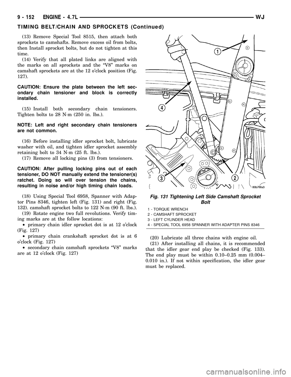
(18) Using Special Tool 6958, Spanner with Adap-
tor Pins 8346, tighten left (Fig. 131) and right (Fig.
132). camshaft sprocket bolts to 122 N´m (90 ft. lbs.).
(19) Rotate engine two full revolutions. Verify tim-
ing marks are at the follow locations:
²primary chain idler sprocket dot is at 12 o'clock
(Fig. 127)
²primary chain crankshaft sprocket dot is at 6
o'clock (Fig. 127)
²secondary chain camshaft sprockets ªV8º marks
are at 12 o'clock (Fig. 127)(20) Lubricate all three chains with engine oil.
(21) After installing all chains, it is recommended
that the idler gear end play be checked (Fig. 133).
The end play must be within 0.10±0.25 mm (0.004±
0.010 in.). If not within specification, the idler gear
must be replaced.
Fig. 131 Tightening Left Side Camshaft Sprocket
Bolt
1 - TORQUE WRENCH
2 - CAMSHAFT SPROCKET
3 - LEFT CYLINDER HEAD
4 - SPECIAL TOOL 6958 SPANNER WITH ADAPTER PINS 8346
9 - 152 ENGINE - 4.7LWJ
TIMING BELT/CHAIN AND SPROCKETS (Continued)
Page 1400 of 2199
DIAGNOSIS AND TESTING - EXHAUST SYSTEM
EXHAUST SYSTEM DIAGNOSIS CHART
CONDITION POSSIBLE CAUSE CORRECTION
EXCESSIVE EXHAUST NOISE1. Leaks at pipe joints. 1. Tighten clamps to specified
torque at leaking joints (Refer to 11
- EXHAUST SYSTEM -
SPECIFICATIONS).
2. Burned or blown out muffler. 2. Replace muffler assembly (Refer
to 11 - EXHAUST SYSTEM/
MUFFLER - REMOVAL). Check
exhaust system.
3. Burned or rusted-out exhaust
pipe.3. Replace exhaust pipe (Refer to
11 - EXHAUST SYSTEM/EXHAUST
PIPE - REMOVAL).
4. Exhaust pipe leaking at manifold
flange.4. Tighten connection attaching nuts
(Refer to 11 - EXHAUST SYSTEM -
SPECIFICATIONS).
5. Exhaust manifold cracked or
broken.5. Replace exhaust manifold (Refer
to 9 - ENGINE/MANIFOLDS/
EXHAUST MANIFOLD -
REMOVAL).
6. Leak between exhaust manifold
and cylinder head.6. Tighten exhaust manifold to
cylinder head stud nuts or bolts
(Refer to 9 - ENGINE -
SPECIFICATIONS).
7. Restriction in muffler or tailpipe. 7. Remove restriction, if possible.
Replace muffler or tailpipe, as
necessary.
8. Exhaust system contacting body
or chassis.8. Re-align exhaust system to clear
surrounding components.
LEAKING EXHAUST GASES1. Leaks at pipe joints. 1. Tighten/replace clamps at leaking
joints (Refer to 11 - EXHAUST
SYSTEM - SPECIFICATIONS).
SPECIFICATIONS
TORQUE
DESCRIPTION N´m Ft. In.
Lbs. Lbs.
Catalytic Converter-to-
Exhaust PipeÐNuts28 Ð 250
Exhaust Pipe-to-ManifoldÐ
Nuts31 23 Ð
Heat Shield RetainingÐ
Nuts2.0 Ð 20DESCRIPTION N´m Ft. In.
Lbs. Lbs.
Muffler-to-Catalytic
Converter
U-bolt clamp 47 35 Ð
Rear Tailpipe HangerÐ
Bolts22 Ð 192
WJEXHAUST SYSTEM 11 - 3
EXHAUST SYSTEM (Continued)
Page 1406 of 2199
NOTE: When servicing the exhaust system, replace
the factory installed uni-clamp with standard u-bolt
clamps.
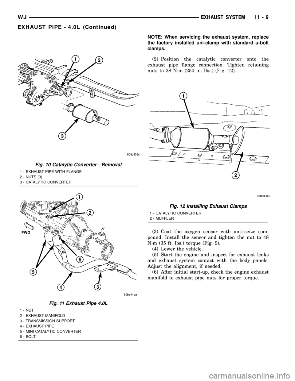
(2) Position the catalytic converter onto the
exhaust pipe flange connection. Tighten retaining
nuts to 28 N´m (250 in. lbs.) (Fig. 12).
(3) Coat the oxygen sensor with anti-seize com-
pound. Install the sensor and tighten the nut to 48
N´m (35 ft. lbs.) torque (Fig. 9).
(4) Lower the vehicle.
(5) Start the engine and inspect for exhaust leaks
and exhaust system contact with the body panels.
Adjust the alignment, if needed.
(6) After initial start-up, check the engine exhaust
manifold to exhaust pipe nuts for proper torque.
Fig. 10 Catalytic ConverterÐRemoval
1 - EXHAUST PIPE WITH FLANGE
2 - NUTS (3)
3 - CATALYTIC CONVERTER
Fig. 11 Exhaust Pipe 4.0L
1 - NUT
2 - EXHAUST MANIFOLD
3 - TRANSMISSION SUPPORT
4 - EXHAUST PIPE
5 - MINI CATALYTIC CONVERTER
6 - BOLT
Fig. 12 Installing Exhaust Clamps
1 - CATALYTIC CONVERTER
2 - MUFFLER
WJEXHAUST SYSTEM 11 - 9
EXHAUST PIPE - 4.0L (Continued)
Page 1408 of 2199
NOTE: When servicing the exhaust system, replace
the factory installed uni-clamp with standard u-bolt
clamps.
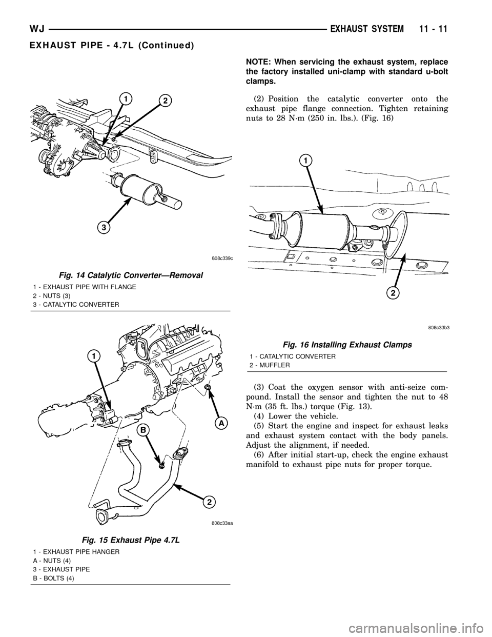
(2) Position the catalytic converter onto the
exhaust pipe flange connection. Tighten retaining
nuts to 28 N´m (250 in. lbs.). (Fig. 16)
(3) Coat the oxygen sensor with anti-seize com-
pound. Install the sensor and tighten the nut to 48
N´m (35 ft. lbs.) torque (Fig. 13).
(4) Lower the vehicle.
(5) Start the engine and inspect for exhaust leaks
and exhaust system contact with the body panels.
Adjust the alignment, if needed.
(6) After initial start-up, check the engine exhaust
manifold to exhaust pipe nuts for proper torque.
Fig. 14 Catalytic ConverterÐRemoval
1 - EXHAUST PIPE WITH FLANGE
2 - NUTS (3)
3 - CATALYTIC CONVERTER
Fig. 15 Exhaust Pipe 4.7L
1 - EXHAUST PIPE HANGER
A - NUTS (4)
3 - EXHAUST PIPE
B - BOLTS (4)
Fig. 16 Installing Exhaust Clamps
1 - CATALYTIC CONVERTER
2 - MUFFLER
WJEXHAUST SYSTEM 11 - 11
EXHAUST PIPE - 4.7L (Continued)
Page 1421 of 2199
FUEL DELIVERY
DESCRIPTION
The fuel delivery system consists of:
²the fuel pump module containing the electric
fuel pump, fuel gauge sending unit (fuel level sensor)
and a separate fuel filter located at bottom of pump
module
²a separate combination fuel filter/fuel pressure
regulator
²fuel tubes/lines/hoses
²quick-connect fittings
²fuel injector rail
²fuel injectors
²fuel tank
²fuel tank filler/vent tube assembly
²fuel tank filler tube cap
²accelerator pedal
²throttle cable
OPERATION
The fuel tank assembly consists of: the fuel tank,
fuel tank shield, fuel tank straps, fuel pump module
assembly, fuel pump module locknut/gasket, and fuel
tank check valve (refer to Emission Control System
for fuel tank check valve information).
A fuel filler/vent tube assembly using a pressure/
vacuum, 1/4 turn fuel filler cap is used. The fuel
filler tube contains a flap door located below the fuel
fill cap.
Also to be considered part of the fuel system is the
evaporation control system. This is designed to
reduce the emission of fuel vapors into the atmo-
sphere. The description and function of the Evapora-
tive Control System is found in Emission Control
Systems.
Both fuel filters (at bottom of fuel pump module
and within fuel pressure regulator) are designed for
extended service. They do not require normal sched-
uled maintenance. Filters should only be replaced if
a diagnostic procedure indicates to do so.
DIAGNOSIS AND TESTING
FUEL PRESSURE LEAK DOWN TEST
Use this test in conjunction with the Fuel Pump
Pressure Test and Fuel Pump Capacity Test.
Check Valve Operation:The electric fuel pump
outlet contains a one-way check valve to prevent fuel
flow back into the tank and to maintain fuel supply
line pressure (engine warm) when pump is not oper-
ational. It is also used to keep the fuel supply line
full of gasoline when pump is not operational. After
the vehicle has cooled down, fuel pressure may drop
to 0 psi (cold fluid contracts), but liquid gasoline willremain in fuel supply line between the check valve
and fuel injectors.Fuel pressure that has
dropped to 0 psi on a cooled down vehicle
(engine off) is a normal condition.When the elec-
tric fuel pump is activated, fuel pressure should
immediately(1±2 seconds) rise to specification.
Abnormally long periods of cranking to restart a
hotengine that has been shut down for a short
period of time may be caused by:
²Fuel pressure bleeding past a fuel injector(s).
²Fuel pressure bleeding past the check valve in
the fuel pump module.
²A defective fuel filter/pressure regulator.
Two #6539, 5/16º, Fuel Line Pressure Test Adapter
Hose Tools are required for the following tests.
(1) Release fuel system pressure. Refer to Fuel
Pressure Release Procedure.
(2) Raise vehicle.
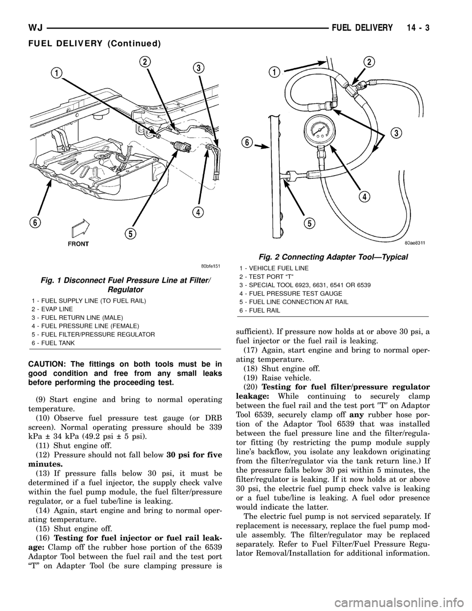
Fuel Line Identification:The fuel filter/pressure
regulator is located in front of the fuel tank and
above the rear axle. It is transversely mounted to a
chassis crossmember (left-to-right). The filter/regula-
tor is equipped with 3 fuel line fittings (2 at one end
and 1 at the other end). The single fitting facing the
left side of the vehicle is the supply line to the fuel
rail (Fig. 1) . The 2 fittings facing the right side of
the vehicle are connected to the fuel tank. Of these 2
fittings, the fitting towards thefrontis used for fuel
return to the fuel tank. The fitting towards therear
is a pressure line. Thisrearfitting must be discon-
nected for the following step.
(3) See previous step. Disconnect fuel pressure line
atrearof filter/regulator. This is a 5/169quick-con-
nect fitting (Fig. 1) . Refer to Quick-Connect Fittings
for procedures.
(4) Obtain correct Fuel Line Pressure Test Adapter
Hose Tool # 6539 for 5/16º fuel lines. Connect one
end of this Special Tool into the disconnected fuel
pressure line. Connect the other end of the Tool into
fitting on filter/regulator.
(5) Lower vehicle.
(6) Disconnect the fuel inlet line at fuel rail. Refer
to Quick-Connect Fittings for procedures. On some
engines, air cleaner housing removal may be neces-
sary before fuel line disconnection.
(7) Obtain a second Fuel Line Pressure Test
Adapter Hose Tool # 6539 for 5/16º fuel lines. Con-
nect this tool between disconnected fuel line and fuel
rail (Fig. 2) .
(8) Connect the 0-414 kPa (0-60 psi) fuel pressure
test gauge (from Gauge Set 5069) to the test port on
the appropriate Adaptor Tool.NOTE: The DRB III
Scan Tool along with the PEP module, the 500
psi pressure transducer, and the transducer-to-
test port adapter may also be used in place of
the fuel pressure gauge.
14 - 2 FUEL DELIVERYWJ
Page 1422 of 2199
CAUTION: The fittings on both tools must be in
good condition and free from any small leaks
before performing the proceeding test.
(9) Start engine and bring to normal operating
temperature.
(10) Observe fuel pressure test gauge (or DRB
screen). Normal operating pressure should be 339
kPa 34 kPa (49.2 psi 5 psi).
(11) Shut engine off.
(12) Pressure should not fall below30 psi for five
minutes.
(13) If pressure falls below 30 psi, it must be
determined if a fuel injector, the supply check valve
within the fuel pump module, the fuel filter/pressure
regulator, or a fuel tube/line is leaking.
(14) Again, start engine and bring to normal oper-
ating temperature.
(15) Shut engine off.
(16)Testing for fuel injector or fuel rail leak-
age:Clamp off the rubber hose portion of the 6539
Adaptor Tool between the fuel rail and the test port
ªTº on Adapter Tool (be sure clamping pressure issufficient). If pressure now holds at or above 30 psi, a
fuel injector or the fuel rail is leaking.
(17) Again, start engine and bring to normal oper-
ating temperature.
(18) Shut engine off.
(19) Raise vehicle.
(20)Testing for fuel filter/pressure regulator
leakage:While continuing to securely clamp
between the fuel rail and the test port9T9on Adaptor
Tool 6539, securely clamp offanyrubber hose por-
tion of the Adaptor Tool 6539 that was installed
between the fuel pressure line and the filter/regula-
tor fitting (by restricting the pump module supply
line's backflow, you isolate any leakdown originating
from the filter/regulator via the tank return line.) If
the pressure falls below 30 psi within 5 minutes, the
filter/regulator is leaking. If it now holds at or above
30 psi, the electric fuel pump check valve is leaking
or a fuel tube/line is leaking. A fuel odor presence
would indicate the latter.
The electric fuel pump is not serviced separately. If
replacement is necessary, replace the fuel pump mod-
ule assembly. The filter/regulator may be replaced
separately. Refer to Fuel Filter/Fuel Pressure Regu-
lator Removal/Installation for additional information.
Fig. 1 Disconnect Fuel Pressure Line at Filter/
Regulator
1 - FUEL SUPPLY LINE (TO FUEL RAIL)
2 - EVAP LINE
3 - FUEL RETURN LINE (MALE)
4 - FUEL PRESSURE LINE (FEMALE)
5 - FUEL FILTER/PRESSURE REGULATOR
6 - FUEL TANK
Fig. 2 Connecting Adapter ToolÐTypical
1 - VEHICLE FUEL LINE
2 - TEST PORT ªTº
3 - SPECIAL TOOL 6923, 6631, 6541 OR 6539
4 - FUEL PRESSURE TEST GAUGE
5 - FUEL LINE CONNECTION AT RAIL
6 - FUEL RAIL
WJFUEL DELIVERY 14 - 3
FUEL DELIVERY (Continued)
Page 1425 of 2199
The regulator is calibrated to maintain fuel system
operating pressure of approximately 339 kPa 34
kPa (49.2 psi 5 psi) at the fuel injectors. It contains
a diaphragm, calibrated springs and a fuel return
valve. The internal fuel filter is also part of the
assembly.
Fuel is supplied to the filter/regulator by the elec-
tric fuel pump. The regulator acts as a check valve to
maintain some fuel pressure when the engine is not
operating. This will help to start the engine. A second
check valve is located at the outlet end of the electric
fuel pump.
If fuel pressure at the pressure regulator exceeds
approximately 49 psi, an internal diaphragm closes.
Excess fuel is then routed into a separate fuel return
line and returned to the fuel tank through the top of
the fuel pump module.
Both fuel filters (at bottom of fuel pump module
and within fuel pressure regulator) are designed for
extended service. They do not require normal sched-
uled maintenance. Filters should only be replaced if
a diagnostic procedure indicates to do so.
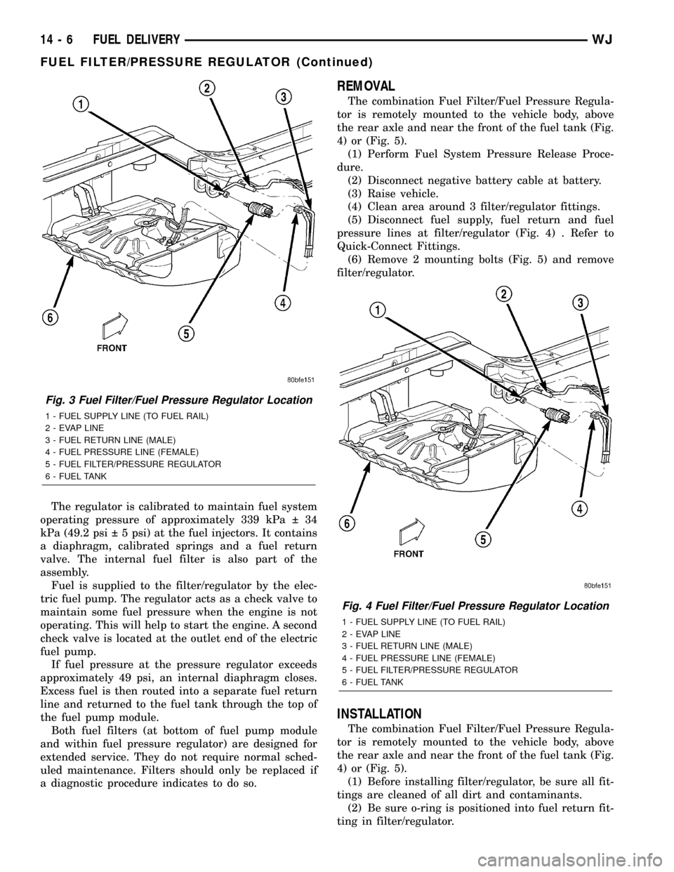
REMOVAL
The combination Fuel Filter/Fuel Pressure Regula-
tor is remotely mounted to the vehicle body, above
the rear axle and near the front of the fuel tank (Fig.
4) or (Fig. 5).
(1) Perform Fuel System Pressure Release Proce-
dure.
(2) Disconnect negative battery cable at battery.
(3) Raise vehicle.
(4) Clean area around 3 filter/regulator fittings.
(5) Disconnect fuel supply, fuel return and fuel
pressure lines at filter/regulator (Fig. 4) . Refer to
Quick-Connect Fittings.
(6) Remove 2 mounting bolts (Fig. 5) and remove
filter/regulator.
INSTALLATION
The combination Fuel Filter/Fuel Pressure Regula-
tor is remotely mounted to the vehicle body, above
the rear axle and near the front of the fuel tank (Fig.
4) or (Fig. 5).
(1) Before installing filter/regulator, be sure all fit-
tings are cleaned of all dirt and contaminants.
(2) Be sure o-ring is positioned into fuel return fit-
ting in filter/regulator.
Fig. 3 Fuel Filter/Fuel Pressure Regulator Location
1 - FUEL SUPPLY LINE (TO FUEL RAIL)
2 - EVAP LINE
3 - FUEL RETURN LINE (MALE)
4 - FUEL PRESSURE LINE (FEMALE)
5 - FUEL FILTER/PRESSURE REGULATOR
6 - FUEL TANK
Fig. 4 Fuel Filter/Fuel Pressure Regulator Location
1 - FUEL SUPPLY LINE (TO FUEL RAIL)
2 - EVAP LINE
3 - FUEL RETURN LINE (MALE)
4 - FUEL PRESSURE LINE (FEMALE)
5 - FUEL FILTER/PRESSURE REGULATOR
6 - FUEL TANK
14 - 6 FUEL DELIVERYWJ
FUEL FILTER/PRESSURE REGULATOR (Continued)