Page 569 of 2100
4C±72
DRIVE SHAFT SYSTEM
Front Propeller Shaft
Front Propeller Shaft and Associated Parts
401RW093
Legend
(1) Bolt, Nut and Washer (Front Axle Side)(2) Front Propeller Shaft
(3) Bolt, Nut and Washer (Transfer Side)
Removal
1. Raise the vehicle on a hoist.
NOTE: Apply alignment marks on the flange at the front
propeller shaft both front and rear side.
401RS020
2. Remove bolt, nut and washer (Front axle side).
3. Remove bolt, nut and washer (Transfer side).
4. Remove front propeller shaft.
Installation
NOTE: Never install the shaft assembly backwards.
Never insert bar between yoke lugs when tightening or
removing bolts. Completely remove the black paint from
the connecting surface of flange coupling on each end of
propeller shaft. Clean so that no foreign matter will be
caught in between.
1. Align the mark which is applied at removal. Install
front propeller shaft and tighten the bolts to the
specified torque.
Torque: 63 N´m (46 lb ft)
Page 576 of 2100

4C±79 DRIVE SHAFT SYSTEM
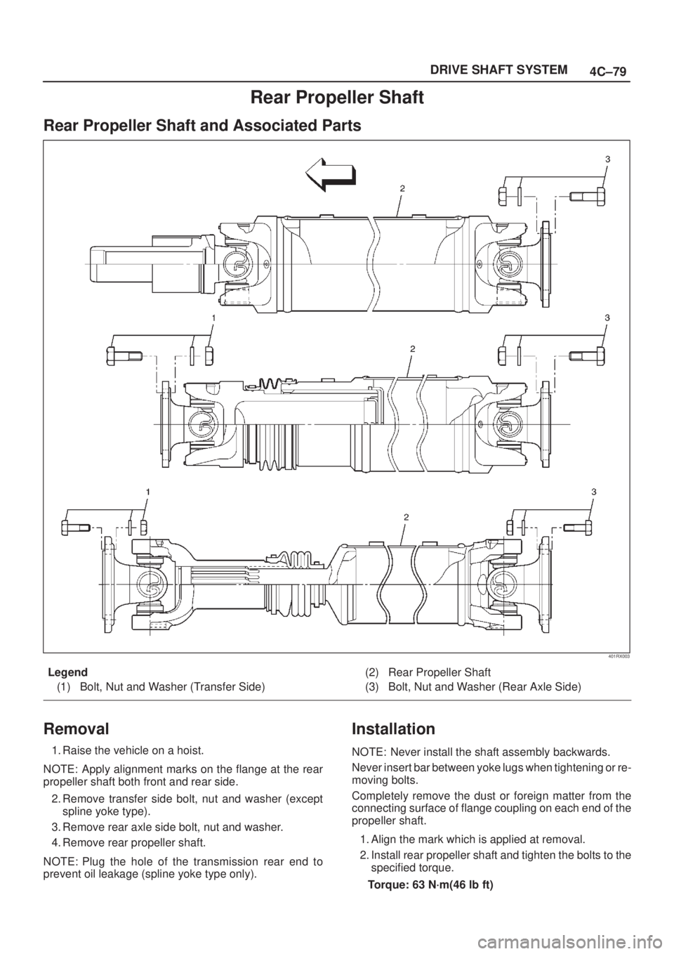
Rear Propeller Shaft
Rear Propeller Shaft and Associated Parts
401RX003
Legend
(1) Bolt, Nut and Washer (Transfer Side)(2) Rear Propeller Shaft
(3) Bolt, Nut and Washer (Rear Axle Side)
Removal
1. Raise the vehicle on a hoist.
NOTE: Apply alignment marks on the flange at the rear
propeller shaft both front and rear side.
2. Remove transfer side bolt, nut and washer (except
spline yoke type).
3. Remove rear axle side bolt, nut and washer.
4. Remove rear propeller shaft.
NOTE: Plug the hole of the transmission rear end to
prevent oil leakage (spline yoke type only).
Installation
NOTE: Never install the shaft assembly backwards.
Never insert bar between yoke lugs when tightening or re-
moving bolts.
Completely remove the dust or foreign matter from the
connecting surface of flange coupling on each end of the
propeller shaft.
1. Align the mark which is applied at removal.
2. Install rear propeller shaft and tighten the bolts to the
specified torque.
Torque: 63 N´m(46 lb ft)
Page 680 of 2100
5B±5 ANTI±LOCK BRAKE SYSTEM
Rear Wheel Speed Sensor
Removal
1. Disconnect harness connector (1).
2. Remove sensor fixing bolt (2) .
3. Remove speed sensor (3).
350R100004
Inspection and Repair
1. Check speed sensor pole piece for presence of
foreign materials; remove any dirt, etc.
2. Check the pole piece for damage, and replace speed
sensor if necessary.
3. Check speed sensor cable for short or open, and
replace with a new one if necessary. To check for
cable short or open, bend or stretch the cable while
checking for continuity.
4. Check the sensor ring for damage including tooth
chipping, and if damaged, replace the axle shaft
assembly. Refer to removal of the sensor ring in
Section
4A2 ªDifferential (Rear)º.
Installation
1. Install speed sensor (3).
2. Tighten the sensor fixing bolt (2) to the specified
torque.
Torque : 24 N´m (17 lb ft)
3. Connect harness connector (1).
350R100004
Page 1504 of 2100

6E±537
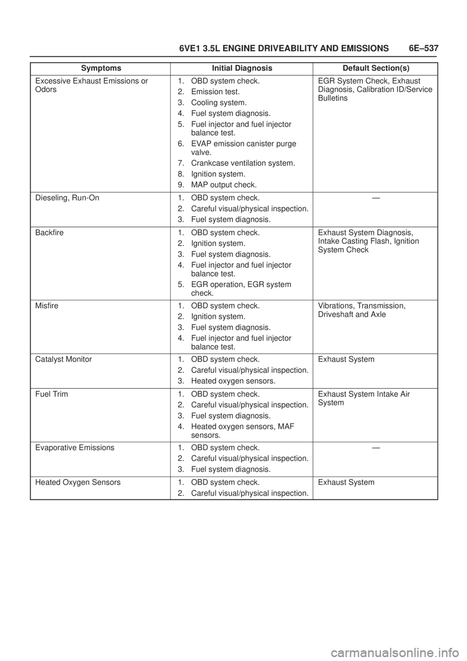
6VE1 3.5L ENGINE DRIVEABILITY AND EMISSIONS
Symptoms Default Section(s)Initial Diagnosis
Excessive Exhaust Emissions or
Odors1. OBD system check.
2. Emission test.
3. Cooling system.
4. Fuel system diagnosis.
5. Fuel injector and fuel injector
balance test.
6. EVAP emission canister purge
valve.
7. Crankcase ventilation system.
8. Ignition system.
9. MAP output check.EGR System Check, Exhaust
Diagnosis, Calibration ID/Service
Bulletins
Dieseling, Run-On1. OBD system check.
2. Careful visual/physical inspection.
3. Fuel system diagnosis.Ð
Backfire1. OBD system check.
2. Ignition system.
3. Fuel system diagnosis.
4. Fuel injector and fuel injector
balance test.
5. EGR operation, EGR system
check.Exhaust System Diagnosis,
Intake Casting Flash, Ignition
System Check
Misfire1. OBD system check.
2. Ignition system.
3. Fuel system diagnosis.
4. Fuel injector and fuel injector
balance test.Vibrations, Transmission,
Driveshaft and Axle
Catalyst Monitor1. OBD system check.
2. Careful visual/physical inspection.
3. Heated oxygen sensors.Exhaust System
Fuel Trim1. OBD system check.
2. Careful visual/physical inspection.
3. Fuel system diagnosis.
4. Heated oxygen sensors, MAF
sensors.Exhaust System Intake Air
System
Evaporative Emissions1. OBD system check.
2. Careful visual/physical inspection.
3. Fuel system diagnosis.Ð
Heated Oxygen Sensors1. OBD system check.
2. Careful visual/physical inspection.Exhaust System