Page 1820 of 2100
8C±8ENTERTAINMENT
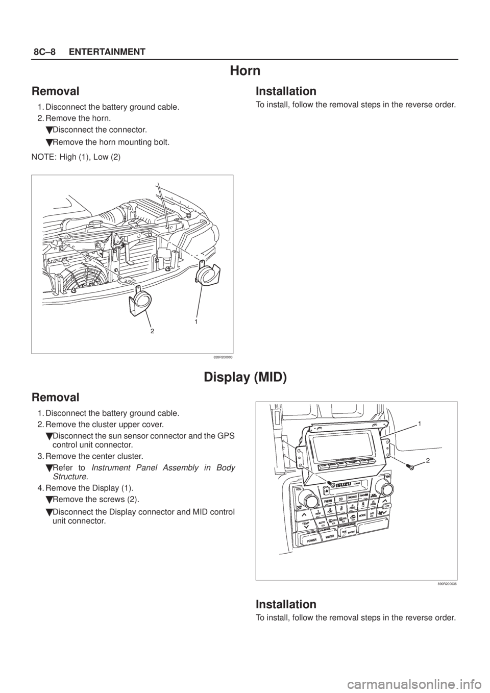
Horn
Removal
1. Disconnect the battery ground cable.
2. Remove the horn.
�Disconnect the connector.
�Remove the horn mounting bolt.
NOTE: High (1), Low (2)
828R200003
Installation
To install, follow the removal steps in the reverse order.
Display (MID)
Removal
1. Disconnect the battery ground cable.
2. Remove the cluster upper cover.
�Disconnect the sun sensor connector and the GPS
control unit connector.
3. Remove the center cluster.
�Refer to
Instrument Panel Assembly in Body
Structure.
4. Remove the Display (1).
�Remove the screws (2).
�Disconnect the Display connector and MID control
unit connector.
890R200036
Installation
To install, follow the removal steps in the reverse order.
Page 1822 of 2100
8C±10ENTERTAINMENT
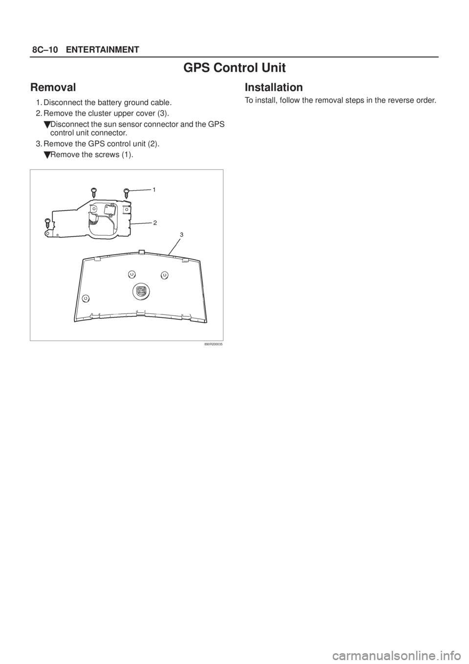
GPS Control Unit
Removal
1. Disconnect the battery ground cable.
2. Remove the cluster upper cover (3).
�Disconnect the sun sensor connector and the GPS
control unit connector.
3. Remove the GPS control unit (2).
�Remove the screws (1).
890R200035
Installation
To install, follow the removal steps in the reverse order.
Page 1829 of 2100
Ye sNo
11. Simultaneously press and hold the RESET key and
the CLOCK key (on the display panel).
2. Turn the ignition switch to the ON positio")
ENTERTAINMENT8C±17
MID Self-Diagnosis
StepActionValue(s)Ye sNo
11. Simultaneously press and hold the RESET key and
the CLOCK key (on the display panel).
2. Turn the ignition switch to the ON position.
Does DIAG appear on the display screen?
ÐGo to Step 2
Check power
supply and
components
connections.
Start
self-diagnosis
again.
2Press and release the CLOCK key (1 time only).
Does DIAG MID appear on the display?
ÐGo to Step 3Ð
3Press and release the CLOCK key (1 time only) to
begin GPS communications diagnosis.
Does GPS OK appear on the display?
ÐGo to Step 5
On ERROR1,
Go to
Step 4
4Repair open circuit between MID and GPS receiver
(I-13±2 ~ I-16±5).
Is the action complete?
ÐGo to Step 1Ð
5Press and release the CLOCK key (1 time only) to
begin fuel injection pulse diagnosis.
Does F-INJ OK appear on the display?
ÐGo to Step 7
On ERROR2,
Go to
Step 6
6Repair open fuel injection pulse circuit (I-13±5 ~
E35±8).
Is the action complete?
ÐGo to Step 1Ð
7Press and release the CLOCK key (1 time only) to
begin fuel remainder pulse diagnosis.
Does F-SENS OK appear on the display?
ÐGo to Step 9
On ERROR3,
Go to
Step 9
8Repair open fuel remainder pulse circuit (I-13±6 ~
E35±48).
Is the action complete?
ÐGo to Step 1Ð
9Press and release the CLOCK key (1 time only) to
begin gyro-sensor diagnosis.
Does GYRO OK appear on the display?
ÐGo to Step 11
On ERROR4,
Go to
Step 10
10Replace the MID control unit.
Is the action complete?
ÐGo to Step 1Ð
111. Press and release the CLOCK key (1 time only) to
begin vehicle speed sensor diagnosis.
2. Drive vehicle.
Does SPEED OK appear on the display?
ÐGo to Step 13
On ERROR5,
Go to
Step 12
12Repair open vehicle speed sensor circuit (I-13±15 ~
E43±3).
Is the action complete?
ÐGo to Step 1Ð
13Press and release ON/OFF key to return to start of
diagnosis screen.
Is the action complete?
ÐGo to Step 1Go to Step 14
14Press and release the SERVICE key.
Is the action complete?
ÐGo to Step 2Ð
Page 1832 of 2100
8C±20ENTERTAINMENT
No COMPASS Display
StepActionValue(s)Ye sNo
1Does ªÐº appear on the display?ÐGo to Step 2Go to Step 3
2Use the self-diagnosis mode to perform MID
self-diagnosis followed by GPS receiver and
gyro-sensor self-diagnosis.
Is the action complete?
ÐGo to Step 1Ð
3Replace the MID and/or DISPLAY.
Is the action complete?
ÐGo to Step 1Ð
No SERVICE Display
StepActionValue(s)Ye sNo
1Is SERVICE displayed?ÐGo to Step 3Go to Step 2
2Replace the MID and/or display.
Is the action complete?
ÐGo to Step 1Ð
3Does SERVICE display change?ÐGo to Step 4Go to Step 5
4CALENDER does not display
MID self-diagnosis followed by GPS receiver
self-diagnosis
Ð
Refer to
self-diagnosis
items
Ð
5MID self-diagnosis followed by GPS receiver
self-diagnosis
Ð
Refer to
self-diagnosis
items
Ð
Page 1833 of 2100

ENTERTAINMENT8C±21
Other Trouble Symptom
ConditionPossible causeCorrection
Elapsed time does not displayAn open circuit between GPS
receiver and MID control unit.Repair an open circuit.
Fuel consumption does not displayMID control unit and/or DISPLAY
not functioning.Replace the MID control unit and/or
DISPLAY.
Possible turning distance does not
changeAn open circuit between MID control
unit No.I-13±6 terminal and PCM
No.E35±48 terminal.Repair an open circuit.
Average fuel consumption does not
displayAn open circuit between MID control
unit No.I-13±5 terminal and PCM
No.E35±8 or MID control unit
NO.I-13±15 terminal and vehicle
speed sensor terminal No.E43±3.Repair an open circuit.
Current fuel consumption does not
displayRefer to average fuel consumption
items.Repair an open circuit.
Compass does not changeAn open circuit between MID control
unit and GPS receiver or insufficient
signal output of gyro sensor.Repair an open circuit and/or replace
gyro sensor.
CALENDER does not displayMID control unit and/or display not
functioning.Replace the MID control unit and/or
DISPLAY.
SERVICE does not changeAn open circuit of the vehicle speed
sensor.Repair an open circuit.
Units cannot be changedMID not functioning.Replace the MID control unit.
Page 1839 of 2100
8D±4
WIRING SYSTEM
Relay / Fuse Box (Engine Room)
D08R200046
Legend
(1) Fuse/Relay Box
(2) Option Box
(3) Diode (Not Used)
(4) Diode
(5) Heater Relay
(6) A/C Compressor Relay
(7) Headlamp Relay RH
(8) Not Used
(9) Fog Lamp Relay
(10) Not Used
(11) Not Used
(12) Thermo Relay
(13) Headlamp Relay LH
(14) Starter Relay
(15) ECM Main
(16) Fuel Pump Relay
(17) Not Used
(18) IG.1 (+B.1 60A)
(19) Main (100A)(20) ECM (30A)
(21) ABS (50A)
(22) IG.2 (+B.2 50A)
(23) Condenser Fan (30A)
(24) Hazard (15A)
(25) Horn (10A)
(26) ACG±S (10A)
(27) Seat Heater (15A)
(28) Blower (15A)
(29) Blower (15A)
(30) A/C (10A)
(31) Headlamp±LH (20A)
(32) Headlamp±RH (20A)
(33) Fog Lamp (15A)
(34) O
2 Sensor (20A)
(35) Fuel Pump (20A)
(36) ECM (15A)
(37) TOD (15A)
(38) Intelligent Suspension Relay (30A)
(39) Condenser Fan Relay
Page 1867 of 2100

METER AND GAUGE8E±1
AXIOM
BODY AND ACCESSORIES
METER AND GAUGE
CONTENTS
Service Precaution 8E±1. . . . . . . . . . . . . . . . . . . . . .
General Description 8E±1. . . . . . . . . . . . . . . . . . . . .
Meter Assembly 8E±2. . . . . . . . . . . . . . . . . . . . . . . . .
General Description 8E±2. . . . . . . . . . . . . . . . . . . . .
Layout for Meters/Gauges, Warning Lights,
Indicator Lights and Illumination Lights 8E±2. . .
Table for Meter/Gauge Connector Terminal
Connections 8E±4. . . . . . . . . . . . . . . . . . . . . . . . . .
Removal 8E±6. . . . . . . . . . . . . . . . . . . . . . . . . . . . .
Installation 8E±6. . . . . . . . . . . . . . . . . . . . . . . . . . . .
Warning Light Bulb and Indicator Light Bulb 8E±6. Removal 8E±6. . . . . . . . . . . . . . . . . . . . . . . . . . . . .
Installation 8E±6. . . . . . . . . . . . . . . . . . . . . . . . . . . .
A/T Shift Indicator Light Bulb 8E±7. . . . . . . . . . . . . .
Removal 8E±7. . . . . . . . . . . . . . . . . . . . . . . . . . . . .
Installation 8E±8. . . . . . . . . . . . . . . . . . . . . . . . . . . .
Vehicle Speed Sensor 8E±9. . . . . . . . . . . . . . . . . . .
Removal 8E±9. . . . . . . . . . . . . . . . . . . . . . . . . . . . .
Installation 8E±9. . . . . . . . . . . . . . . . . . . . . . . . . . . .
Fuel Tank Unit 8E±9. . . . . . . . . . . . . . . . . . . . . . . . . .
Removal 8E±9. . . . . . . . . . . . . . . . . . . . . . . . . . . . .
Main Data and Specifications 8E±10. . . . . . . . . . . . .
Service Precaution
WARNING: THIS VEHICLE HAS A SUPPLEMENTAL
RESTRAINT SYSTEM (SRS). REFER TO THE SRS
COMPONENT AND WIRING LOCATION VIEW IN
ORDER TO DETERMINE WHETHER YOU ARE
PERFORMING SERVICE ON OR NEAR THE SRS
COMPONENTS OR THE SRS WIRING. WHEN YOU
ARE PERFORMING SERVICE ON OR NEAR THE SRS
COMPONENTS OR THE SRS WIRING, REFER TO
THE SRS SERVICE INFORMATION. FAILURE TO
FOLLOW WARNINGS COULD RESULT IN POSSIBLE
AIR BAG DEPLOYMENT, PERSONAL INJURY, OR
OTHERWISE UNNEEDED SRS SYSTEM REPAIRS.
CAUTION: Always use the correct fastener in the
proper location. When you replace a fastener, use
ONLY the exact part number for that application.
ISUZU will call out those fasteners that require a
replacement after removal. ISUZU will also call out
the fasteners that require thread lockers or thread
sealant. UNLESS OTHERWISE SPECIFIED, do not
use supplemental coatings (Paints, greases, or other
corrosion inhibitors) on threaded fasteners or
fastener joint interfaces. Generally, such coatings
adversely affect the fastener torque and the joint
clamping force, and may damage the fastener. When
you install fasteners, use the correct tightening
sequence and specifications. Following these
instructions can help you avoid damage to parts and
systems.
General Description
The circuit consists of the starter switch, meter assembly,
vehicle speed sensor, transmission switch, lighting
switch, turn signal switch, thermo unit, oil pressure unit,
Powertrain Control Module (PCM), fuel tank unit, 4WD
switch, oil pressure switch, parking brake switch, brake
fluid switch, seat belt switch, illumination controller, meter
and ambient sensor.
Page 1871 of 2100

METER AND GAUGE8E±5
Connector A
TerminalFunction
1Ð
2Intelligent suspension indicator light
3TOD indicator light ªRearº
4Ð
5TOD indicator light ªAUTOº
6Ð
7TOD indicator light ªFrontº
8A/T shift indicator light ª3º
9A/T shift indicator light ªDº
10A/T shift indicator light ª2º
11SRS ± air bag warning light
12Ground
13Battery
14Stater switch
15A/T oil temperature warning light
16Seat belt indicator light
17Charge warning light
18Ð
19Ð
20Ð
21A/T shift indicator light ªLº
22ABS warning light
23Ð
24Ð
25Reduced power warning light
26Oil pressure warning light
27Check trans warning light
28MIL(check engine) warning light
29Check TOD
30Engine coolant temperature gauge
Connector B
TerminalFunction
1A/T shift indicator light ªRº
2A/T shift indicator light
3A/T shift indicator light ªNº
4A/T shift indicator light ªPº
5Illumination light
6Engine revolution pulse
7Speed sensor pulse
8Turn signal indicator light (LH)
9Brake warning light
10High beam indicator light (+)
11High beam indicator light (±)
12Turn signal indicator light (RH)
13Turn signal indicator light
14Ð
15Illumination light
16Ground
Connector C
TerminalFunction
1Starter switch
2Ð
3Fuel gauge
4Low fuel warning light
5Cruise set indicator light
6Ð
7Ð
8Ð
9Ð
10Sport mode indicator light
11Ð
12Winter drive indicator light
13Power drive indicator light
14Ð
Ye sNo
1Does ªÐº appear on the display?ÐGo to Step 2Go to Step 3
2Use the self-diagnosis mode to perform MID
self-diagnosis followed by GPS")

D08R200046
Legend
(1) Fuse/Relay Box
(2) Option Box
(3) Diode (Not Used)
(4) Diode
(5) Heater Relay
(6) A/C Compressor Relay
(7) Headlamp Relay RH
(8")