Page 584 of 2100

AXIOM
DRIVELINE/AXLE
TRANSFER CASE (TOD)
CONTENTS
Service Precaution 4D2±1. . . . . . . . . . . . . . . . . . . . . .
General Description 4D2±2. . . . . . . . . . . . . .")
4D2±1 TRANSFER CASE (TOD)
AXIOM
DRIVELINE/AXLE
TRANSFER CASE (TOD)
CONTENTS
Service Precaution 4D2±1. . . . . . . . . . . . . . . . . . . . . .
General Description 4D2±2. . . . . . . . . . . . . . . . . . . . .
Removal and Installation of Tfansfer Case
Assembly 4D2±3. . . . . . . . . . . . . . . . . . . . . . . . . . . . . .
Removal 4D2±4. . . . . . . . . . . . . . . . . . . . . . . . . . . . .
Installation 4D2±4. . . . . . . . . . . . . . . . . . . . . . . . . . . .
Transfer Rear Oil Seal 4D2±6. . . . . . . . . . . . . . . . . . .
Removal 4D2±6. . . . . . . . . . . . . . . . . . . . . . . . . . . . .
Installation 4D2±6. . . . . . . . . . . . . . . . . . . . . . . . . . . .
TOD Control Unit 4D2±8. . . . . . . . . . . . . . . . . . . . . . . .
Removal 4D2±8. . . . . . . . . . . . . . . . . . . . . . . . . . . . .
Installation 4D2±8. . . . . . . . . . . . . . . . . . . . . . . . . . . .
Unit Repair 4D2±9. . . . . . . . . . . . . . . . . . . . . . . . . . . . .
Disassembly and Reassembly of Major
Components 4D2±9. . . . . . . . . . . . . . . . . . . . . . . . .
Disassembly 4D2±10. . . . . . . . . . . . . . . . . . . . . . . . . .
Reassembly 4D2±10. . . . . . . . . . . . . . . . . . . . . . . . . .
Transfer Cover Assembly 4D2±13. . . . . . . . . . . . . . . .
Disassembly 4D2±13. . . . . . . . . . . . . . . . . . . . . . . . . .
Inspection and Repair 4D2±14. . . . . . . . . . . . . . . . . . Reassembly 4D2±15. . . . . . . . . . . . . . . . . . . . . . . . . .
Clutch Pack and Clutch Cam
(Transfer Case Assembly) 4D2±16. . . . . . . . . . . . . . .
Disassembly 4D2±16. . . . . . . . . . . . . . . . . . . . . . . . . .
Reassembly 4D2±18. . . . . . . . . . . . . . . . . . . . . . . . . .
Chain, Sprocket and Mechanical Lock
(Transfer Case Assembly) 4D2±20. . . . . . . . . . . . . . .
Disassembly 4D2±21. . . . . . . . . . . . . . . . . . . . . . . . . .
Reassembly 4D2±22. . . . . . . . . . . . . . . . . . . . . . . . . .
Transfer Case Assembly 4D2±24. . . . . . . . . . . . . . . . .
Disassembly 4D2±24. . . . . . . . . . . . . . . . . . . . . . . . . .
Reassembly 4D2±26. . . . . . . . . . . . . . . . . . . . . . . . . .
Inspection and Repair
(Transfer Case Assembly) 4D2±28. . . . . . . . . . . . . .
Main Data and Specification 4D2±32. . . . . . . . . . . . . .
General Specification 4D2±32. . . . . . . . . . . . . . . . . .
Torque Specifications 4D2±33. . . . . . . . . . . . . . . . . .
Torque Specifications (Cont'd) 4D2±34. . . . . . . . . . .
Torque Specifications (Cont'd) 4D2±35. . . . . . . . . . .
Special Tools 4D2±36. . . . . . . . . . . . . . . . . . . . . . . . . . .
Service Precaution
WARNING: THIS VEHICLE HAS A SUPPLEMENTAL
RESTRAINT SYSTEM (SRS). REFER TO THE SRS
COMPONENT AND WIRING LOCATION VIEW IN
ORDER TO DETERMINE WHETHER YOU ARE
PERFORMING SERVICE ON OR NEAR THE SRS
COMPONENTS OR THE SRS WIRING. WHEN YOU
ARE PERFORMING SERVICE ON OR NEAR THE SRS
COMPONENTS OR THE SRS WIRING, REFER TO
THE SRS SERVICE INFORMATION. FAILURE TO
FOLLOW WARNINGS COULD RESULT IN POSSIBLE
AIR BAG DEPLOYMENT, PERSONAL INJURY, OR
OTHERWISE UNNEEDED SRS SYSTEM REPAIRS.CAUTION: Always use the correct fastener in the
proper location. When you replace a fastener, use
ONLY the exact part number for that application.
ISUZU will call out those fasteners that require a
replacement after removal. ISUZU will also call out
the fasteners that require thread lockers or thread
sealant. UNLESS OTHERWISE SPECIFIED, do not
use supplemental coatings (Paints, greases, or other
corrosion inhibitors) on threaded fasteners or
fastener joint interfaces. Generally, such coatings
adversely affect the fastener torque and the joint
clamping force, and may damage the fastener. When
you install fasteners, use the correct tightening
sequence and specifications. Following these
instructions can help you avoid damage to parts and
systems.
Page 585 of 2100

General Description
A04R200003
The Torque-On-Demand (TOD) is an
electronically-controlled torque-split 4-wheel drive
system with the following features.
Shifting Between Hig")
4D2±2
TRANSFER CASE (TOD)
General Description
A04R200003
The Torque-On-Demand (TOD) is an
electronically-controlled torque-split 4-wheel drive
system with the following features.
Shifting Between High and Low Ranges
The shifting mechanism consists of the cam and shaft rail
assembly, the high/low shift motor and the encoder. The
encoder is built-in to the motor.
The encoder senses high/low range shift motor rotation
position and sends this data to the TOD control unit.
Based on this data, the TOD control unit adjusts motor
rotation speed or stops the motor.
The shifting between the high and low ranges using the
TOD switch only is possible. The vehicle must be stopped
or nearly stopped (vehicle speed less than 2 km/h (1.2
mph) and engine speed less than 1,500 rpm), the
automatic transmission selector level must be in the
neutral (N) position, and the brakes must be applied.
Electronically-controlled Wet-type Multiple
Disc Clutch
The clutch automatically provides the optimum drive
power to the front wheels of the vehicle in response to
varying road surface conditions when the vehicle is
operated in the TOD mode. The delivered power ranges
from 0% to 100% of power train output. Superior
operational stability is maintained over a wide range of
operating conditions.
Front Output Drive
Front output drive is provided by a chain. This reduces the
loud noise associated with 4-wheel drive operation.
Oil Pump Lubrication
An oil pump is used to lubricate the transfer. This ensures
stable multiple-disc clutch operation and maintains the
lubricating oil at a constant temperature.
Page 593 of 2100

Disassembly
1. Remove the drain plug from the transfer case and
drain the oil.
2. Remove the speedometer sensor and driven gear.
3. Remove the front and rear speed sensor o")
4D2±10
TRANSFER CASE (TOD)
Disassembly
1. Remove the drain plug from the transfer case and
drain the oil.
2. Remove the speedometer sensor and driven gear.
3. Remove the front and rear speed sensor of the
harness assembly from the transfer cover assembly.
NOTE: Use care to prevent damage to speed sensor
when removing speed sensor.
4. Disconnect the clutch solenoid coil, 4H and 4L switch
harness connector.
�Remove the harness bracket from the transfer
cover.
261RY00009
5. Remove the connector bracket from the transfer
case.
�Remove the harness assembly and shift motor
harness connector from the connector bracket.
261RY00010
6. Remove the 4H and 4L switch from the transfer case.
7. Remove the shift motor assembly from the transfer
cover.
8. Using the flange holder J±8614±11, remove the end
nut.
Remove the washers, oil seals, front and rear
companion flange.
262RY00012
9. Remove the transfer cover retaining bolts and the
transfer cover assembly from the transfer case
assembly.
NOTE: When removing the transfer cover assembly, use
care to prevent damage to oil seal.
10. Remove the breather hose from the transfer case.
Reassembly
1. Apply recommended liquid gasket (LOCTITE 598 or
its equivalent) uniformly to the transfer case and
cover fitting surface.
261RY00011
Page 595 of 2100

6. Apply recommended liquid gasket (LOCTITE 598 or
its equivalent) to the transfer cover and shift motor
assembly fitting surface.
261R200003
7. Install the shift motor ass")
4D2±12
TRANSFER CASE (TOD)
6. Apply recommended liquid gasket (LOCTITE 598 or
its equivalent) to the transfer cover and shift motor
assembly fitting surface.
261R200003
7. Install the shift motor assembly to the transfer cover
assembly.
Torque: 10 N´m (87 lb in)
8. Install the 4H and 4L switch.
Torque: 24 N´m (17 lb ft)
9. Install the harness assembly and shift motor harness
connector to the connector bracket.
10. Install the front and rear speed sensors to the transfer
cover.
Torque: 5 N´m (43 lb in)
11. Connect the harness assembly connector to the
clutch solenoid coil harness connector and 4H and 4L
switch.
�Fix the harness with harness bracket.
261RY00009
12. Install the driven gear and speedometer sensor to the
transfer case.
Torque: 25 N´m (19 lb ft)
261RY00034
13. Remove the filler plug and fill the transfer case with
ATF DEXRON)±II or III.
14. Wind the sealing tape around the filler plug thread and
tighten the plug to the specified torque.
Torque: 25 N´m (19 lb ft)
261RY00026
15. Install the breather hose to the transfer case.
Page 599 of 2100
4D2±16
TRANSFER CASE (TOD)
Clutch Pack and Clutch Cam (Transfer Case Assembly)
266RY00015
Legend
(1) Transfer Case Assembly
(2) Snap Ring
(3) Wave Spring
(4) Cam Pulley
(5) Cam Ball(6) Cam and Coil Housing Assembly
(7) Thrust Bearing
(8) Armature Plate
(9) Insulator Washer
(10) Clutch Pack Assembly
(11) Lockup Fork Spring
Disassembly
1. Remove the lockup fork spring.
2. Remove the thrust bearing and cam and coil housing
assembly from the output shaft.
NOTE: When the cam and coil housing assembly is
removed, the cam balls may be detached together with
the housing. Pay attention not to lose the ball.
261RY00020
Page 600 of 2100
4D2±17 TRANSFER CASE (TOD)
3. Remove the cam ball (3 pieces).
4. Remove the cam pulley.
266RY00005
5. Remove the wave spring.
266RY00006
6. Using snap ring pliers, remove the snap ring.
NOTE: Use care to prevent damage to snap ring.
266RY00007
7. Remove the armature plate, insulator washer and
clutch pack assembly as a package.
266RY00008
Page 601 of 2100
4D2±18
TRANSFER CASE (TOD)
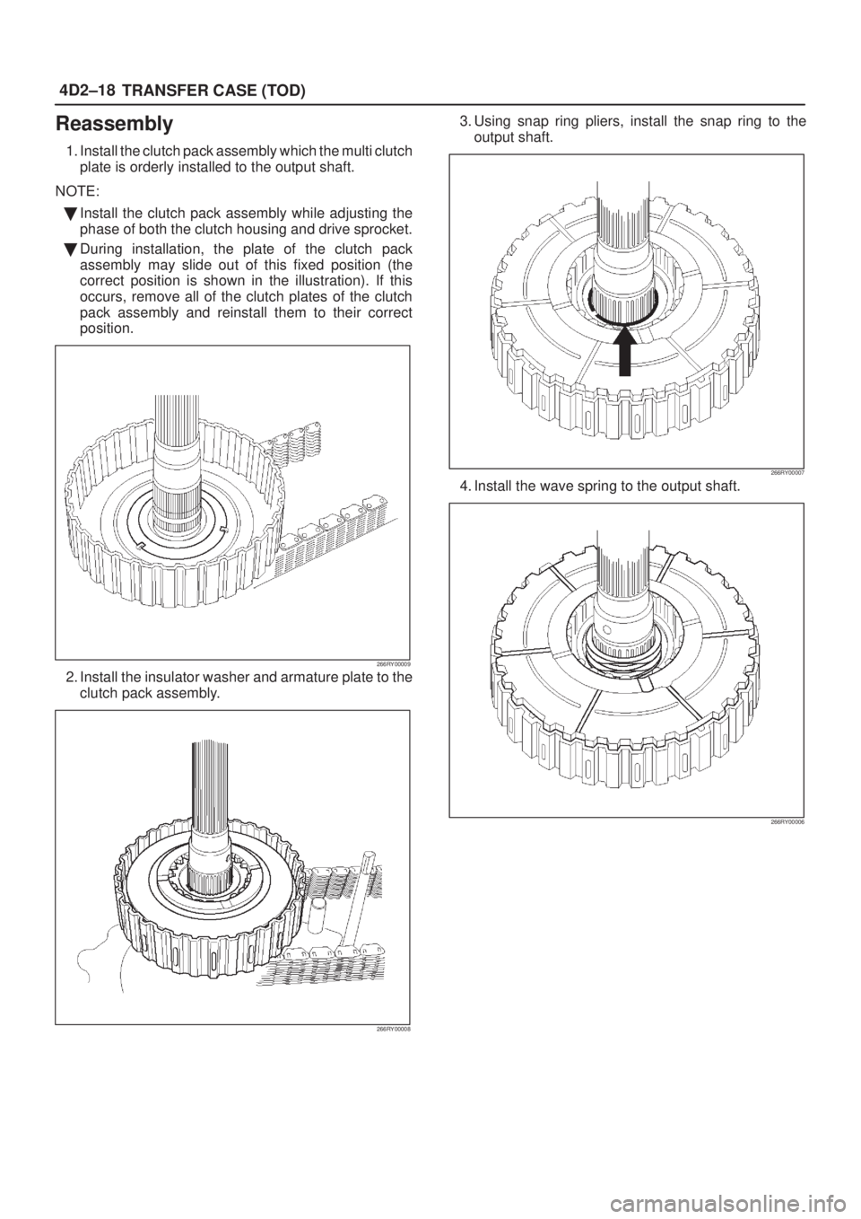
Reassembly
1. Install the clutch pack assembly which the multi clutch
plate is orderly installed to the output shaft.
NOTE:
�Install the clutch pack assembly while adjusting the
phase of both the clutch housing and drive sprocket.
�During installation, the plate of the clutch pack
assembly may slide out of this fixed position (the
correct position is shown in the illustration). If this
occurs, remove all of the clutch plates of the clutch
pack assembly and reinstall them to their correct
position.
266RY00009
2. Install the insulator washer and armature plate to the
clutch pack assembly.
266RY00008
3. Using snap ring pliers, install the snap ring to the
output shaft.
266RY00007
4. Install the wave spring to the output shaft.
266RY00006
Page 613 of 2100

Bearing
Check the profile of the needle, roller, ball, and thrust
bearings. Wash the bearings with clean detergent
completely, and dry with air.
NOTE: If the bearing is rot")
4D2±30
TRANSFER CASE (TOD)
Bearing
Check the profile of the needle, roller, ball, and thrust
bearings. Wash the bearings with clean detergent
completely, and dry with air.
NOTE: If the bearing is rotated excessively, the rollers
may be damaged. So, rotate the bearing slowly with your
hand. Apply grease to the bearing, and check the
smoothness of the bearing while slowly rotating the race
with your hand.
Allowable limit : 0.23 mm (0.009 in)
226RW143
Lockup Fork Spring
Check the lockup fork spring for distortion, cracking, and
wear. If defects are observed, replace the part.
Multi Plate Disk Clutch
�If the burned, mirror-surfaced clutch facing, or
scraping is observed on the clutch plates, clutch
housing, armature plate, and insulator washer,
replace the parts.
266R200003
Legend
(1) Clutch Housing
(2) Clutch Plate
(3) Insulator Washer
(4) Armature Plate
Coil Assembly
�Check the resistance of the coil with a tester. If
defects are observed, replace the coil assembly.
Standard : 1.7+0.3� (at ordinary temperature)
Allowable limit : 1.0~5.0�
261RY00022
Cam Pulley, Cam Ball, and Cam & Coil
Housing
�Check the cam balls and cam for excessive wear or
damage. If defective, replace the parts.
266RW016

Clutch Pack and Clutch Cam (Transfer Case Assembly)
266RY00015
Legend
(1) Transfer Case Assembly
(2) Snap Ring
(3) Wave Spring
(4) Cam Pulley
(5) Cam Ball(6) Cam and Coil H")

3. Remove the cam ball (3 pieces).
4. Remove the cam pulley.
266RY00005
5. Remove the wave spring.
266RY00006
6. Using snap ring pliers, remove the snap ring.
NOTE: Use car")