2002 ISUZU AXIOM ECU
[x] Cancel search: ECUPage 464 of 2100
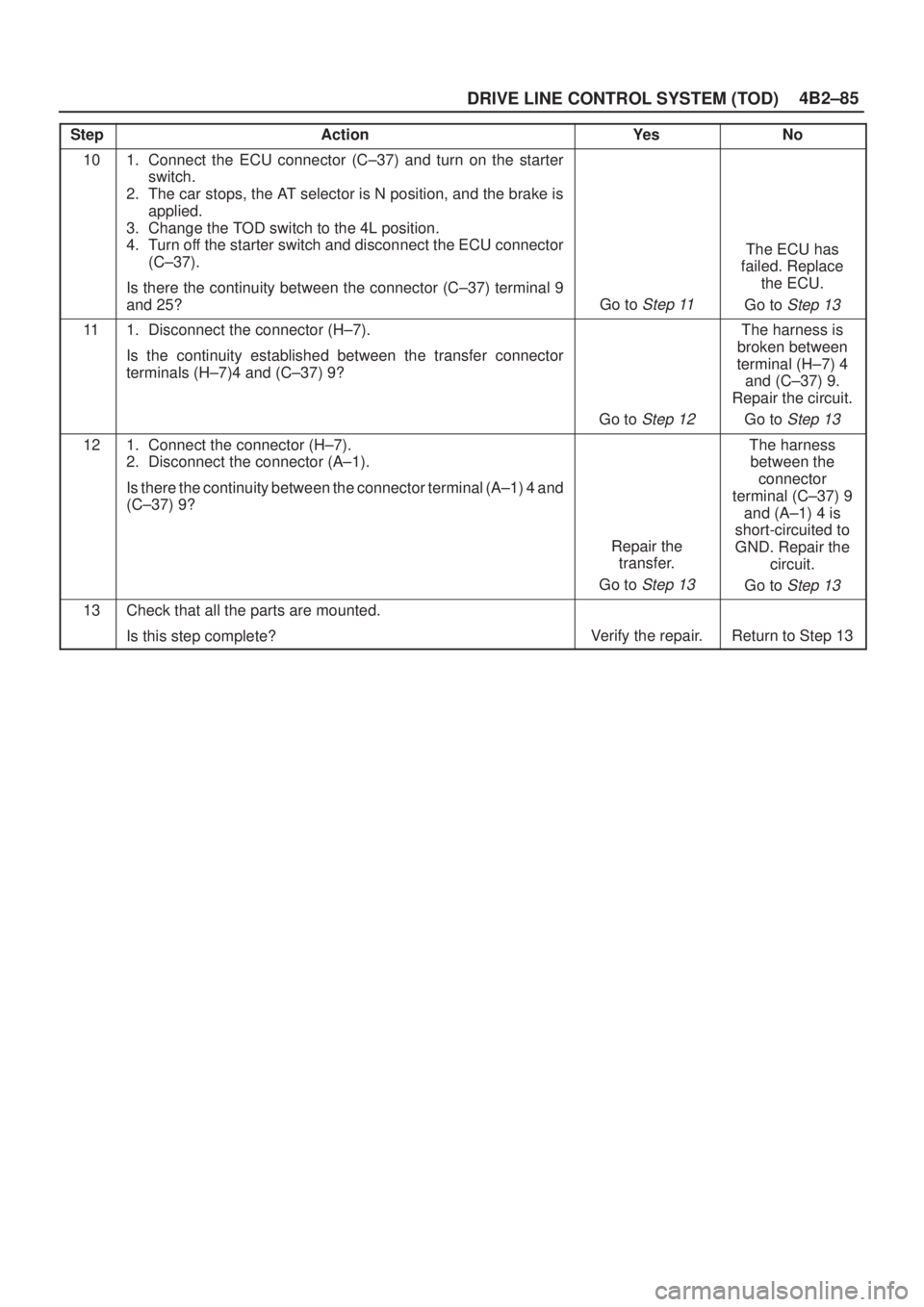
4B2±85
DRIVE LINE CONTROL SYSTEM (TOD)
StepNo Ye s Action
101. Connect the ECU connector (C±37) and turn on the starter
switch.
2. The car stops, the AT selector is N position, and the brake is
applied.
3. Change the TOD switch to the 4L position.
4. Turn off the starter switch and disconnect the ECU connector
(C±37).
Is there the continuity between the connector (C±37) terminal 9
and 25?
Go to Step 11
The ECU has
failed. Replace
the ECU.
Go to
Step 13
111. Disconnect the connector (H±7).
Is the continuity established between the transfer connector
terminals (H±7)4 and (C±37) 9?
Go to Step 12
The harness is
broken between
terminal (H±7) 4
and (C±37) 9.
Repair the circuit.
Go to
Step 13
121. Connect the connector (H±7).
2. Disconnect the connector (A±1).
Is there the continuity between the connector terminal (A±1) 4 and
(C±37) 9?
Repair the
transfer.
Go to
Step 13
The harness
between the
connector
terminal (C±37) 9
and (A±1) 4 is
short-circuited to
GND. Repair the
circuit.
Go to
Step 13
13Check that all the parts are mounted.
Is this step complete?
Verify the repair.Return to Step 13
Page 467 of 2100
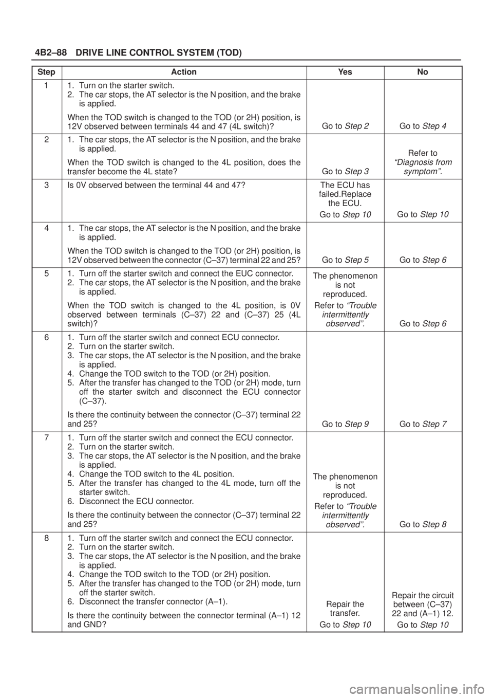
DRIVE LINE CONTROL SYSTEM (TOD) 4B2±88
StepActionYe sNo
11. Turn on the starter switch.
2. The car stops, the AT selector is the N position, and the brake
is applied.
When the TOD switch is changed to the TOD (or 2H) position, is
12V observed between terminals 44 and 47 (4L switch)?
Go to Step 2Go to Step 4
21. The car stops, the AT selector is the N position, and the brake
is applied.
When the TOD switch is changed to the 4L position, does the
transfer become the 4L state?
Go to Step 3
Refer to
ªDiagnosis from
symptomº.
3Is 0V observed between the terminal 44 and 47?The ECU has
failed.Replace
the ECU.
Go to
Step 10Go to Step 10
41. The car stops, the AT selector is the N position, and the brake
is applied.
When the TOD switch is changed to the TOD (or 2H) position, is
12V observed between the connector (C±37) terminal 22 and 25?
Go to Step 5Go to Step 6
51. Turn off the starter switch and connect the EUC connector.
2. The car stops, the AT selector is the N position, and the brake
is applied.
When the TOD switch is changed to the 4L position, is 0V
observed between terminals (C±37) 22 and (C±37) 25 (4L
switch)?The phenomenon
is not
reproduced.
Refer to
ªTrouble
intermittently
observedº.
Go to Step 6
61. Turn off the starter switch and connect ECU connector.
2. Turn on the starter switch.
3. The car stops, the AT selector is the N position, and the brake
is applied.
4. Change the TOD switch to the TOD (or 2H) position.
5. After the transfer has changed to the TOD (or 2H) mode, turn
off the starter switch and disconnect the ECU connector
(C±37).
Is there the continuity between the connector (C±37) terminal 22
and 25?
Go to Step 9Go to Step 7
71. Turn off the starter switch and connect the ECU connector.
2. Turn on the starter switch.
3. The car stops, the AT selector is the N position, and the brake
is applied.
4. Change the TOD switch to the 4L position.
5. After the transfer has changed to the 4L mode, turn off the
starter switch.
6. Disconnect the ECU connector.
Is there the continuity between the connector (C±37) terminal 22
and 25?
The phenomenon
is not
reproduced.
Refer to
ªTrouble
intermittently
observedº.
Go to Step 8
81. Turn off the starter switch and connect the ECU connector.
2. Turn on the starter switch.
3. The car stops, the AT selector is the N position, and the brake
is applied.
4. Change the TOD switch to the TOD (or 2H) position.
5. After the transfer has changed to the TOD (or 2H) mode, turn
off the starter switch.
6. Disconnect the transfer connector (A±1).
Is there the continuity between the connector terminal (A±1) 12
and GND?
Repair the
transfer.
Go to
Step 10
Repair the circuit
between (C±37)
22 and (A±1) 12.
Go to
Step 10
Page 471 of 2100
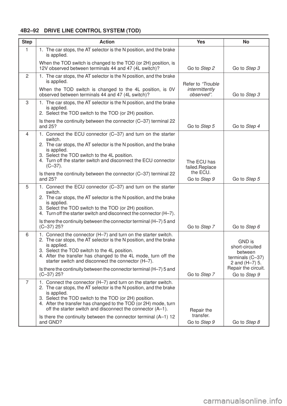
DRIVE LINE CONTROL SYSTEM (TOD) 4B2±92
StepActionYe sNo
11. The car stops, the AT selector is the N position, and the brake
is applied.
When the TOD switch is changed to the TOD (or 2H) position, is
12V observed between terminals 44 and 47 (4L switch)?
Go to Step 2Go to Step 3
21. The car stops, the AT selector is the N position, and the brake
is applied.
When the TOD switch is changed to the 4L position, is 0V
observed between terminals 44 and 47 (4L switch)?
Refer to ªTrouble
intermittently
observedº.
Go to Step 3
31. The car stops, the AT selector is the N position, and the brake
is applied.
2. Select the TOD switch to the TOD (or 2H) position.
Is there the continuity between the connector (C±37) terminal 22
and 25?
Go to Step 5Go to Step 4
41. Connect the ECU connector (C±37) and turn on the starter
switch.
2. The car stops, the AT selector is the N position, and the brake
is applied.
3. Select the TOD switch to the 4L position.
4. Turn off the starter switch and disconnect the ECU connector
(C±37).
Is there the continuity between the connector (C±37) terminal 22
and 25?
The ECU has
failed.Replace
the ECU.
Go to
Step 9Go to Step 5
51. Connect the ECU connector (C±37) and turn on the starter
switch.
2. The car stops, the AT selector is the N position, and the brake
is applied.
3. Select the TOD switch to the TOD (or 2H) position.
4. Turn off the starter switch and disconnect the connector (H±7).
Is there the continuity between the connector terminal (H±7) 5 and
(C±37) 25?
Go to Step 7Go to Step 6
61. Connect the connector (H±7) and turn on the starter switch.
2. The car stops, the AT selector is the N position, and the brake
is applied.
3. Select the TOD switch to the 4L position.
4. After the transfer has changed to the 4L mode, turn off the
starter switch and disconnect the connector (H±7).
Is there the continuity between the connector terminal (H±7) 5 and
(C±37) 25?
Go to Step 7
GND is
short-circuited
between
terminals (C±37)
2 and (H±7) 5.
Repair the circuit.
Go to
Step 9
71. Connect the connector (H±7) and turn on the starter switch.
2. The car stops, the AT selector is the N position, and the brake
is applied.
3. Select the TOD switch to the TOD (or 2H) position.
4. After the transfer has changed to the TOD (or 2H) mode, turn
off the starter switch and disconnect the connector (A±1).
Is there the continuity between the connector terminal (A±1) 12
and GND?
Repair the
transfer.
Go to
Step 9Go to Step 8
Page 474 of 2100

4B2±95
DRIVE LINE CONTROL SYSTEM (TOD)
StepActionYe sNo
1Start the engine.
When the TOD switch is selected to the TOD position, is 0V
observed between terminals 42 and 47?
Go to Step 2Go to Step 4
21. The car stops, the AT selector is N position, and the brake is
applied.
2. Select the TOD switch to the 4L position.
Is 0V observed between terminals 42 and 47?
Go to Step 3Go to Step 4
31. The car stops, the AT selector is N position, and the brake is
applied.
When the TOD switch is selected to the 4L position, is 12V
observed between the terminal 19 and 47?The phenomenon
is not
reproduced.
Refer to
ªTroubles
intermittently
observedº.
The ECU has
failed.Replace
the ECU.
Go to
Step 8
41. The car stops, the AT selector is N position, and the brake is
applied.
When the TOD switch is selected to the 2H position, is the battery
voltage observed between the terminal 23 and 47.
Go to Step 5Go to Step 7
5When the TOD switch is selected to the TOD position (TOD
mode), is 0 ~ 1V observed between terminals 23 and 47?
Go to Step 6Go to Step 7
61. The car stops, the AT selector is N position, and the brake is
applied.
When the TOD switch is selected to the 4L position, is 0V
observed between terminals 23 and 47?Repair the circuit
or check the
ªFront Axle
Disconnectº.
(Refer to
section
4B
)
Go to
Step 8Go to Step 7
7Is any of the trouble codes 28 (P1760), 32 (P1761) and 33
(P1762) recorded?Examine the
trouble based on
ªDiagnosis from
Trouble Codesº.The ECU has
failed. Replace
the ECU.
Go to
Step 8
8Check that all the parts are mounted.
Is this step complete?
Verify the repair.Go to Step 8
Page 476 of 2100

4B2±97
DRIVE LINE CONTROL SYSTEM (TOD)
StepActionYe sNo
1Start the engine.
When the TOD switch is selected to the TOD position, is 0V
observed between terminals 42 and 47?
Go to Step 2Go to Step 6
21. The car stops, the AT selector is N position, and the brake is
applied.
When the TOD switch is selected to the 4L position, is 0V
observed between terminals 42 and 47?
Go to Step 3Go to Step 6
31. The car stops, the AT selector is N position, and the brake is
applied.
2. Select the TOD switch to the 2H position.
Is 5V observed between terminals 42 and 47?
Go to Step 4Go to Sep 6
4Is 12V observed between terminals 7 and 47?
Go to Step 5
Replace the
ECU.
Go to
Step 10
5Is 12V observed between terminals 19 and 47?The phenomenon
is not
reproduced.
Refer to
ªTroubles
intermittently
observedº.
The ECU has
failed.Replace
the ECU.
Go to
Step 10
61. The car stops, the AT selector is N position, and the brake is
applied.
When the TOD switch is selected to the 2H position, is the battery
voltage observed between terminals 23 and 47?
Go to Step 7Go to Step 9
71. The car stops, the AT selector is N position, and the brake is
applied.
When the TOD switch is selected to the TOD position, is 0V
observed between terminals 23 and 47?
Go to Step 8Go to Step 9
81. The car stops, the AT selector is N position, and the brake is
applied.
When the TOD switch is selected to the 4L position, is 0V
observed between terminals 23 and 47?Repair the circuit
or check the
ªFront Axle
Disconnectº.
(Refer to
section
4B
)
Go to
Step 10Go to Step 9
9Is any of the trouble codes 28 (P1760), 32 (P1761) and 33
(P1762) recorded?Examine the
trouble based on
ªDiagnosis from
Trouble Codesº.The ECU has
failed. Replace
the ECU.
Go to
Step 10
10Check that all the parts are mounted.
Is this step complete?
Verify the repair.Go to Step 10
Page 478 of 2100
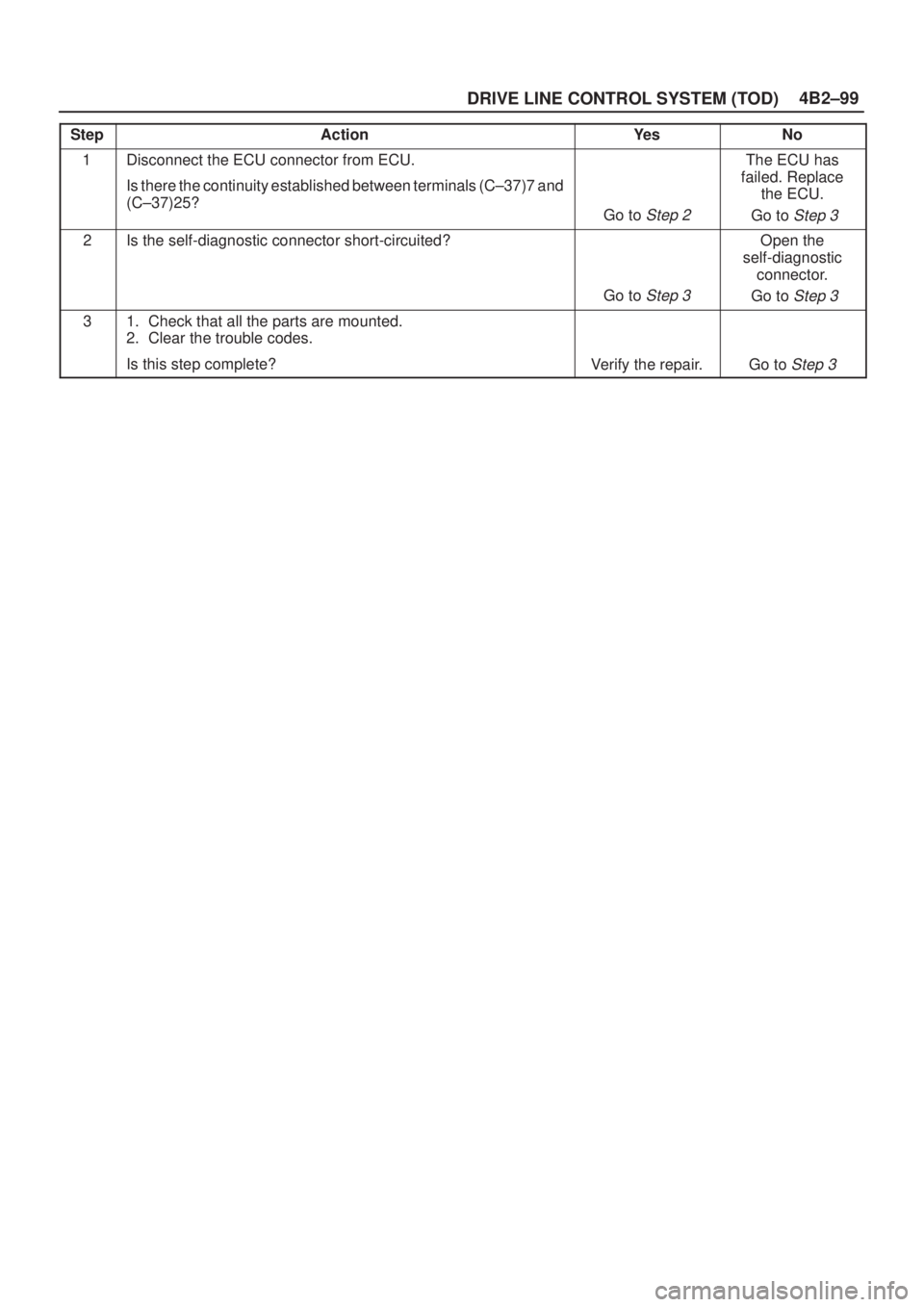
4B2±99
DRIVE LINE CONTROL SYSTEM (TOD)
StepActionYe sNo
1Disconnect the ECU connector from ECU.
Is there the continuity established between terminals (C±37)7 and
(C±37)25?
Go to Step 2
The ECU has
failed. Replace
the ECU.
Go to
Step 3
2Is the self-diagnostic connector short-circuited?
Go to Step 3
Open the
self-diagnostic
connector.
Go to
Step 3
31. Check that all the parts are mounted.
2. Clear the trouble codes.
Is this step complete?
Verify the repair.Go to Step 3
Page 480 of 2100
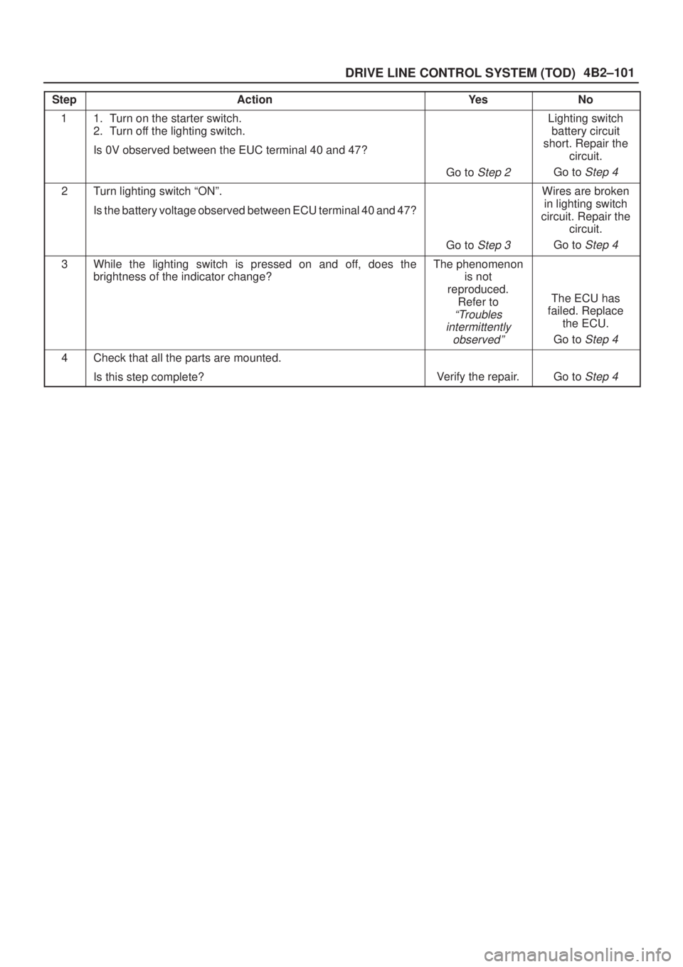
4B2±101
DRIVE LINE CONTROL SYSTEM (TOD)
StepActionYe sNo
11. Turn on the starter switch.
2. Turn off the lighting switch.
Is 0V observed between the EUC terminal 40 and 47?
Go to Step 2
Lighting switch
battery circuit
short. Repair the
circuit.
Go to
Step 4
2Turn lighting switch ªONº.
Is the battery voltage observed between ECU terminal 40 and 47?
Go to Step 3
Wires are broken
in lighting switch
circuit. Repair the
circuit.
Go to
Step 4
3While the lighting switch is pressed on and off, does the
brightness of the indicator change?The phenomenon
is not
reproduced.
Refer to
ªTroubles
intermittently
observedº
The ECU has
failed. Replace
the ECU.
Go to
Step 4
4Check that all the parts are mounted.
Is this step complete?
Verify the repair.Go to Step 4
Page 483 of 2100

DRIVE LINE CONTROL SYSTEM (TOD) 4B2±104
StepActionYe sNo
1Are the front and rear tires in specified size?
Go to Step 2
Replace the tires
with specified
ones, and service
the new tires.
Go to
Step 16
2Is the tire pressure correct?
Go to Step 3
Inflate the tires
with specified
pressure.
Go to
Step 16
3Are the tires free from abnormal wear?
Go to Step 4
Replace the tires
with specified
ones, and service
the new tires.
Go to
Step 16
4Are different types of tires used?
Go to Step 5
Replace the tires
with specified
ones, and service
the new tires.
Go to
Step 16
51. Start the engine.
2. Select the TOD switch to the TOD position.
3. Fully turn the steering to the left (or right) end, and select the D
range and start the creep run.
Does the tight corner braking occur? Is the judder with chug-chug
sound observed? * Use caution on the operation.
Go to Step 6 Go to Step 11
61. Select the TOD switch to the 2H position.
2. Fully turn the steering to the left (or right) end, and select the D
range and start the creep run.
Does the tight corner braking occur? Is the judder with chug-chug
sound observed? * Use caution on the operation.
Go to Step 7 Go to Step 14
7Is an LSD mounted to the rear differential? Go to Step 8 Go to Step 9
8Is the genuine LSD oil used in the rear differential?
Go to Step 9
Replace the
differential oil.
Go to
Step 16
9Does the engine output the power correctly?
Go to Step 10
Check the
engine.
Go to
Step 16
10Do the speed sensors work correctly? (Check trouble codes.)The ECU has
failed. Replace
the ECU.
Go to
Step 16
Replace the
speed sensors.
Go to
Step 16
11Is the tight corner braking observed only when the brake is
applied?
Go to Step 12
Conduct full
steering under
WOT.
Go to
Step 5
121. Turn on the starter switch.
Is 8 ~ 10 V observed between terminals 33 and 47?
Go to Step 13
Repair the circuit
of the ECU
connector
terminal 33 (ABS
IN).
Go to
Step 16