Page 1343 of 2100
 P0601 PCM Memory
060RY014
Circuit Description
The powertrain control module (PCM) used in this vehicle
utilizes an ele")
6E±376
6VE1 3.5L ENGINE DRIVEABILITY AND EMISSIONS
Diagnostic Trouble Code (DTC) P0601 PCM Memory
060RY014
Circuit Description
The powertrain control module (PCM) used in this vehicle
utilizes an electrically erasable programmable read-only
memory (EEPROM). The EEPROM contains program
information and the calibrations required for engine,
transmission, and powertrain diagnostics operation.
Unlike the PROM used in past applications, the EEPROM
is not replaceable. When the PCM is replaced or a
calibration update is required, the PCM must be
programmed using a Tech 2. Refer to
On-Vehicle Service
in Powertrain Control Module and Sensors for the
EEPROM programming procedure.
Conditions for Setting the DTC
�The PCM detects an internal program fault (check sum
error).
Action Taken When the DTC Sets
�The PCM will illuminate the malfunction indicator lamp
(MIL) the first time the fault is detected.�The PCM will store conditions which were present
when the DTC was set as Freeze Frame and in the
Failure Records data.
Conditions for Clearing the MIL/DTC
�The PCM will turn the MIL ªOFFº on the third
consecutive trip cycle during which the diagnostic has
been run and the fault condition is no longer present.
�A history DTC P0601 will clear after 40 consecutive
warm-up cycles have occurred without a fault.
�DTC P0601 can be cleared by using the Tech 2 ªClear
Infoº function or by disconnecting the PCM battery
feed.
Diagnostic Aids
�DTC P0601 indicates that the contents of the
EEPROM have changed since the PCM was
programmed. The only possible repair is PCM
replacement. Remember to program the replacement
PCM with the correct software and calibration for the
vehicle.
Page 1344 of 2100
6E±377
6VE1 3.5L ENGINE DRIVEABILITY AND EMISSIONS
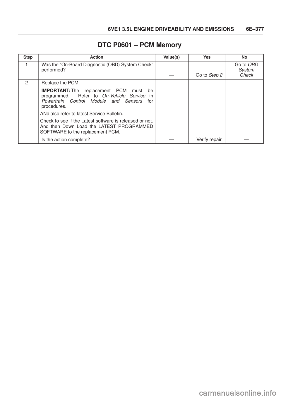
DTC P0601 ± PCM Memory�
StepActionValue(s)Ye sNo
1Was the ªOn-Board Diagnostic (OBD) System Checkº
performed?
ÐGo to Step 2
Go to OBD
System
Check
2Replace the PCM.
IMPORTANT:The replacement PCM must be
programmed. Refer to
On-Vehicle Service in
Powertrain Control Module and Sensors for
procedures.
ANd also refer to latest Service Bulletin.
Check to see if the Latest software is released or not.
And then Down Load the LATEST PROGRAMMED
SOFTWARE to the replacement PCM.
Is the action complete?
ÐVerify repairÐ
Page 1346 of 2100
6E±379
6VE1 3.5L ENGINE DRIVEABILITY AND EMISSIONS
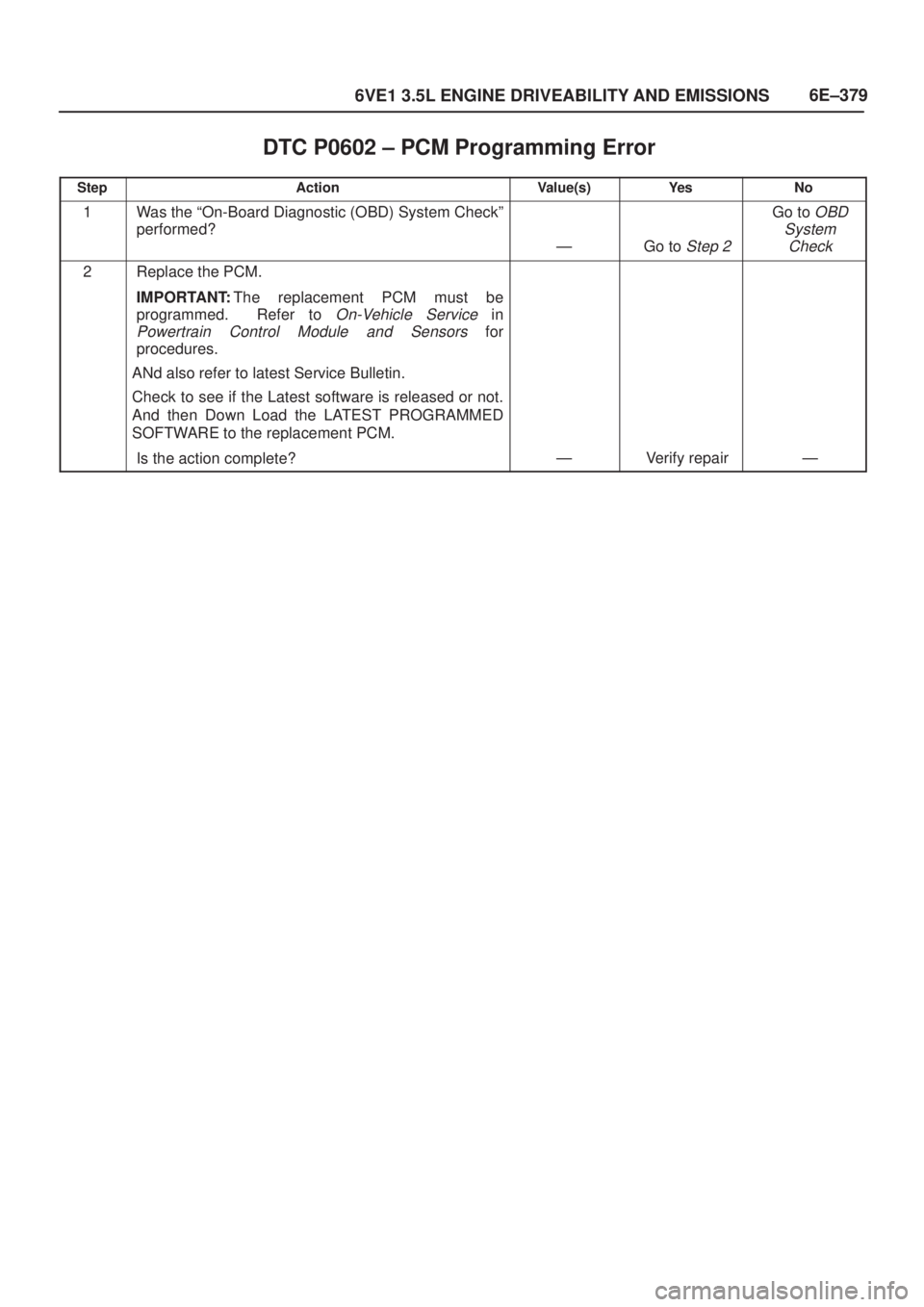
DTC P0602 ± PCM Programming Error�
StepActionValue(s)Ye sNo
1Was the ªOn-Board Diagnostic (OBD) System Checkº
performed?
ÐGo to Step 2
Go to OBD
System
Check
2Replace the PCM.
IMPORTANT:The replacement PCM must be
programmed. Refer to
On-Vehicle Service in
Powertrain Control Module and Sensors for
procedures.
ANd also refer to latest Service Bulletin.
Check to see if the Latest software is released or not.
And then Down Load the LATEST PROGRAMMED
SOFTWARE to the replacement PCM.
Is the action complete?
ÐVerify repairÐ
Page 1348 of 2100
6E±381
6VE1 3.5L ENGINE DRIVEABILITY AND EMISSIONS
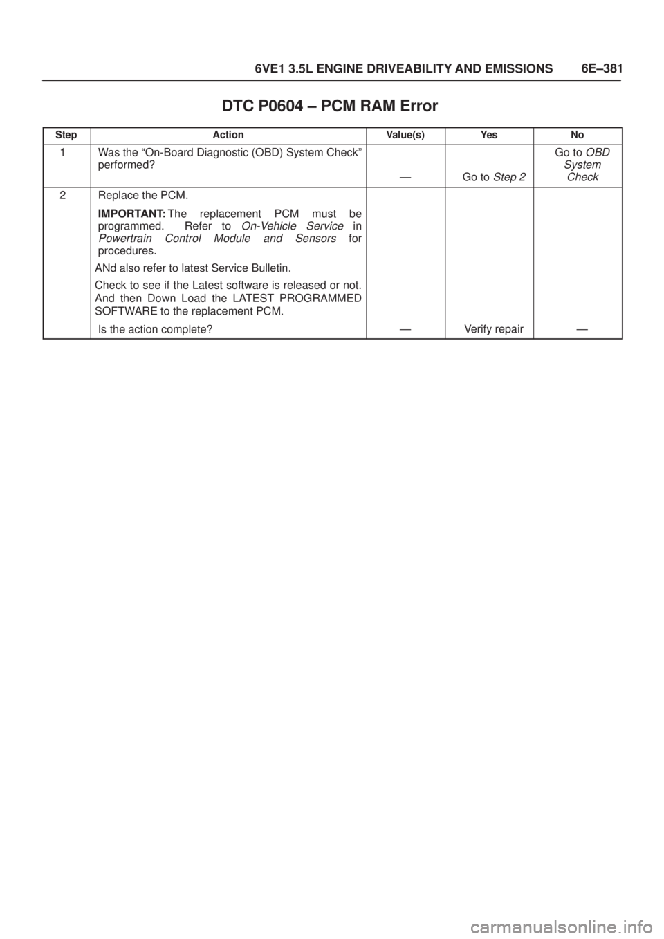
DTC P0604 ± PCM RAM Error�
StepActionValue(s)Ye sNo
1Was the ªOn-Board Diagnostic (OBD) System Checkº
performed?
ÐGo to Step 2
Go to OBD
System
Check
2Replace the PCM.
IMPORTANT:The replacement PCM must be
programmed. Refer to
On-Vehicle Service in
Powertrain Control Module and Sensors for
procedures.
ANd also refer to latest Service Bulletin.
Check to see if the Latest software is released or not.
And then Down Load the LATEST PROGRAMMED
SOFTWARE to the replacement PCM.
Is the action complete?
ÐVerify repairÐ
Page 1350 of 2100
6E±383
6VE1 3.5L ENGINE DRIVEABILITY AND EMISSIONS
DTC P0606 ± PCM Internal Performance�
StepActionValue(s)Ye sNo
1Was the ªOn-Board Diagnostic (OBD) System Checkº
performed?
ÐGo to Step 2
Go to OBD
System
Check
2Replace the PCM.
IMPORTANT:The replacement PCM must be
programmed. Refer to
On-Vehicle Service in
Powertrain Control Module and Sensors for
procedures.
ANd also refer to latest Service Bulletin.
Check to see if the Latest software is released or not.
And then Down Load the LATEST PROGRAMMED
SOFTWARE to the replacement PCM.
Is the action complete?
ÐVerify repairÐ
Page 1351 of 2100

P1106 MAP Sensor Circuit Intermittent High Voltage
060R200051
Circuit Description
The manifold absolute pressure (MAP")
6E±384
6VE1 3.5L ENGINE DRIVEABILITY AND EMISSIONS
Diagnostic Trouble Code (DTC)
P1106 MAP Sensor Circuit Intermittent High Voltage
060R200051
Circuit Description
The manifold absolute pressure (MAP) sensor responds
to changes in intake manifold pressure (vacuum). The
MAP sensor signal voltage to the PCM varies from below
2 volts at idle (high vacuum) to above 4 volts with the
ignition ªONº, engine not running or at wide-open throttle
(low vacuum).
The MAP sensor is used to determine manifold pressure
changes while the liner EGR flow test diagnostic is being
run (refer to
DTC P0401), to determine engine vacuum
level for some other diagnostics and to determine
barometric pressure (BARO). The PCM compares the
MAP sensor signal to a calculated MAP based on throttle
position and various engine load factors. If the PCM
detects a MAP signal that is intermittently above the
calculated value, DTC P1106 will set.
Conditions for Setting the DTC
�No TP sensor DTCs are present.
�Engine is running for at least 10 seconds.
�Throttle angle is below 3% if engine speed is below
1000 RPM.
�Throttle angle is below 10% if engine speed is above
1000 RPM.
�The MAP sensor indicates an intermittent manifold
absolute pressure above 80 kPa for a total of
approximately 5 seconds over a 16-second period of
time.
Action Taken When the DTC Sets
�The PCM will not illuminate the malfunction indicator
lamp (MIL).
�The PCM will store conditions which were present
when the DTC was set as Failure Records data only.
This information will not be stored as Freeze Frame
data.
Conditions for Clearing the MIL/DTC
�A history DTC P1106 will clear after 40 consecutive
warm-up cycles have occurred without a fault.
�DTC P1106 can be cleared by using the Tech 2 ªClear
Infoº function or by disconnecting the PCM battery
feed.
Diagnostic Aids
Check for the following conditions:
�Leaking or plugged vacuum supply line to the MAP
sensor.
�Inspect PCM harness connectors for backed-out
terminals, improper mating, broken locks, improperly
formed or damaged terminals, and poor
terminal-to-wire connection.
�Inspect the wiring harness for damage. If the harness
appears to be OK, observe the MAP display on the
Tech 2 while moving connectors and wiring harnesses
related to the sensor. A change in the display will
indicate the location of the fault.
Reviewing the Failure Records vehicle mileage since the
diagnostic test last failed may help determine how often
Page 1352 of 2100

6E±385
6VE1 3.5L ENGINE DRIVEABILITY AND EMISSIONS
the condition that caused the DTC to be set occurs. This
may assist in diagnosing the condition.
�The MAP sensor shares a 5 Volt Reference with the
Fuel Tank Pressure sensor. Check the 5 Volt reference
if this DTC is also set.�The MAP sensor shares a ground with the Fuel Tank
Pressure sensor and the ECT Sensor. Check the
ground if these other DTCs are also set.
DTC P1106 ± MAP Sensor Circuit Intermittent High Voltage�
StepActionValue(s)Ye sNo
1Was the ªOn-Board Diagnostic (OBD) System Checkº
performed?
ÐGo to Step 2
Go to OBD
System
Check
2Is DTC P0108 also set?
Ð
Go to DTC
P0108
chart
first
Go to Step 3
3Are DTC P1111, P1115, and/or P1120 also set?ÐGo to Step 6Go to Step 4
4Check for a poor sensor ground circuit terminal
connection at the MAP sensor.
Was a problem found?
ÐGo to Step 9Go to Step 5
5Check the MAP signal circuit between the MAP sensor
connector and the PCM for an intermittent short to
voltage.
Was a problem found?
ÐGo to Step 10Go to Step 8
6Check for an intermittent short to voltage on the 5 volt
reference circuit between the PCM and the following
components:
�MAP sensor
�EGR valve
�TP sensor
Was a problem found?
ÐGo to Step 10Go to Step 7
7Check for a poor sensor ground circuit terminal
connection at the PCM.
Was a problem found?
ÐGo to Step 9Go to Step 8
8Check for an intermittent open or a faulty splice in the
sensor ground circuit.
Was a problem found?
ÐGo to Step 10
Refer to
Diagnostic
Aids
9Replace the faulty harness connector terminal for the
sensor ground circuit.
Is the action complete?
ÐVerify repairÐ
10Locate and repair the intermittent open/short circuit in
the wiring harness as necessary.
Is the action complete?
ÐVerify repairÐ
Page 1353 of 2100

P1107 MAP Circuit Intermittent Low Voltage
060R200051
Circuit Description
The manifold absolute pressure (MAP) sensor")
6E±386
6VE1 3.5L ENGINE DRIVEABILITY AND EMISSIONS
Diagnostic Trouble Code (DTC)
P1107 MAP Circuit Intermittent Low Voltage
060R200051
Circuit Description
The manifold absolute pressure (MAP) sensor responds
to changes in intake manifold pressure (vacuum). The
MAP sensor signal voltage to the powertrain control
module (PCM) varies from below 2 volts at idle (high
vacuum) to above 4 volts with the ignition ªONº, engine
not running or at wide-open throttle (low vacuum).
The MAP sensor is used to determine manifold pressure
changes while the linear EGR flow test diagnostic is being
run (refer to
DTC P0401), to determine engine vacuum
level for some other diagnostics and to determine
barometric pressure (BARO). The PCM compares the
MAP sensor signal to a calculated MAP based on throttle
position and various engine load factors. If the PCM
detects a MAP signal that is intermittently below the
calculated value, DTC P1107 will be set.
Conditions for Setting the DTC
�No TP sensor DTCs are present.
�Engine is running.
�Ignition voltage is more than 11 volts.
�Throttle angle is above 1% if engine speed is less than
1000 RPM.
�Throttle angle is above 3% if engine speed is above
1000 RPM.
�The MAP sensor indicates an intermittent manifold
absolute pressure below 11 kPa for a total ofapproximately 5 seconds over a 16-second period of
time.
Action Taken When the DTC Sets
�The PCM will not illuminate the malfunction indicator
lamp (MIL).
�The PCM will store conditions which were present
when the DTC was set as Failure Records data only.
This information will not be stored as Freeze Frame
data.
Conditions for Clearing the MIL/DTC
�A history DTC P1107 will Clear after 40 consecutive
warm-up cycles have occurred without a fault.
�DTC P1107 can be cleared by using the Tech 2 ªClear
Infoº function or by disconnecting the PCM battery
feed.
Diagnostic Aids
Check for the following conditions:
�Poor connection at PCM ± Inspect harness connectors
for backed-out terminals, improper mating, broken
locks, improperly formed or damaged terminals, and
poor terminal-to-wire connection.
�The MAP Sensor shares a 5 Volt reference with the
EGR Valve. If these codes are also set, it could indicate
a problem with the 5 Volt reference circuit or
components itself.
�The MAP Sensor share a ground with the EGR Valve
and the IAT Sensor.