Page 911 of 2100
6B±7
Thermostat
Thermostat and Associated Parts
031RW001
Legend
(1) Thermostat Housing
(2) Thermostat
(3) Outlet Pipe
Removal
1. Disconnect battery ground cable.
2. Drain en")
ENGINE COOLING (6VE1 3.5L)6B±7
Thermostat
Thermostat and Associated Parts
031RW001
Legend
(1) Thermostat Housing
(2) Thermostat
(3) Outlet Pipe
Removal
1. Disconnect battery ground cable.
2. Drain engine coolant from the radiator and engine.
3. Disconnect radiator hose from the inlet pipe.
4. Remove thermostat housing.
5. Remove thermostat(2).
Inspection
Suspend the thermostat in a water±filled container using
thin wire. Place a thermometer next to the thermostat.
Do not directly heat the thermostat.
Gradually increase the water temperature. Stir the water
so that the entire water is same temperature.
031RS003Confirm the temperature when the valve first begins to
open.
Valve opening temperature 74.5C ~ 78.5�C
(166.1�F ~ 173.3�F)
Confirm the temperature when the valve is fully opened.
Valve full open temperature and lift More than
8.5mm (0.33 in) at 90�C (194�F)
Make necessary repair and parts replacement if extreme
wear or damage is found during inspection.
Installation
1. Install thermostat into the outlet pipe(4) making sure
that the air hole is in the up position.
2. Install thermostat housing and tighten bolts to the
specified torque.
Torque: 25 N´m (18 lb ft)
3. Installation rubber hose.
4. Replenish engine coolant (EC).
5. Start engine and check for EC leakage.
Page 921 of 2100
6C±4
ENGINE FUEL (6VE1 3.5L)
Fuel Filter
Removal
CAUTION: When repair to the fuel system has been
completed, start engine and check the fuel system
for loose connection or leakage. For the fuel system
diagnosis, see Section ªDriveability and Emissionº.
1. Disconnect battery ground cable.
2. Remove Fuel filler cap(1).
140R100023
Legend
(1) Fuel Filler Cap
(2) Receive Rubber Drain
3. Disconnect fuel hoses(1) from fuel filter on both
engine side and fuel tank side.
4. Fuel filter fixing bolt(2).
�Remove the fuel filter fixing bolt(2) on fuel filter
holder.5. Remove fuel filter(3).
041RW003
Legend
(1) Fuel Hose
(2) Fuel Filter Fixing Bolt
(3) Fuel Filter
Inspection
1. Replace the fuel filter if the fuel leaks from fuel filter
body or if the fuel filter body itself is damaged.
2. Replace the filter if it is clogged with dirt or sediment.
3. Check clogged drain port of the receive rubber by the
foreign material, repair or clear if found clog it.
Page 928 of 2100

Removal
CAUTION: When repair to the fuel system has been
completed, start engine and check the fuel system
for loose connection or leakage. For the fuel system
diagnosis")
6C±11 ENGINE FUEL (6VE1 3.5L)
Removal
CAUTION: When repair to the fuel system has been
completed, start engine and check the fuel system
for loose connection or leakage. For the fuel system
diagnosis, see Section ªDriveability and Emissionº.
1. Drain the fuel from the fuel tank, refer to the ªFuel
Pump Flow Testº in this section.
2. Disconnect battery ground cable.
3. Loosen fuel filler cap to reduce the pressure in fuel
tank.
4. Support underneath of the fuel tank assembly (1) with
a lifter.
5. Disconnect fuel feed hose (7) and fuel return hose (8)
near the fuel filter.
NOTE: Plug both ends of the fuel hoses to prevent fuel
leakage.
6. Disconnect fuel filler hose (5) and fuel vent hose (6) at
the fuel filler neck.
NOTE: Cover fuel hoses to prevent any dust entering.
7. Remove two bolts (4) and remove separator.
8. Remove the five fuel tank assembly fixing bolts (2)
and one nut (3).
9. Lower the tank and disconnect the wiring connectors
(9, 10).
Installation
1. Raise the fuel tank assembly (1) and connect the
wiring connectors (9, 10).
2. Install fuel tank assembly along with protectors and
tighten the five fixing bolts (2) and one nut (3) to the
specified torque.
Torque: 68 N´m (50 lb ft)
3. Install the separator and tighten two bolts (4).
Torque: 10 N´m (95 lb in)
4. Connect fuel filler hose (5) and fuel vent hose and clip
them firmly.
5. Connect fuel feed hose (7) and fuel return hose(8),
and clip them firmly.
6. Tighten fuel filler cap until at least three clicks are
heard.
7. Connect battery ground cable.
Page 973 of 2100
6E±6
6VE1 3.5L ENGINE DRIVEABILITY AND EMISSIONS
Specifications
Tightening Specifications
ApplicationN´mLb Ft.Lb In.
EGR Bolt2518Ð
Engine Coolant Temperature Sensor3022Ð
Fuel Drain Plug2014Ð
Fuel Pressure Regulator Attaching Screw3Ð26
Fuel Rail Bolts2518Ð
Fuel Tank Undercover Retaining Bolts3627Ð
Heated Oxygen Sensor5540Ð
Lower Intake Manifold to Engine Block Bolts2518Ð
Lower Intake Manifold to Engine Block Nuts2518Ð
Spark Plugs1813Ð
Throttle Body Mounting Bolts10Ð87
Common Chamber to Lower Intake Manifold Bolts2518Ð
VSS Retaining Bolt1612Ð
Page 1505 of 2100
 Sensor
Removal Procedure
1. Disconnect the negative battery cable.
2. Disconnect the electrical conne")
6E±538
6VE1 3.5L ENGINE DRIVEABILITY AND EMISSIONS
On Vehicle
Service Crankshaft Position
(CKP) Sensor
Removal Procedure
1. Disconnect the negative battery cable.
2. Disconnect the electrical connector to the CKP
sensor.
3. Remove one bolt and the CKP sensor from the right
side of the engine block, just behind the mount.
NOTE: Use caution to avoid any hot oil that might drip
out.
TS22909
Inspection Procedure
1. Inspect the sensor O-ring for cracks or leaks.
2. Replace the O-ring if it is worn or damaged.
3. Lubricate the new O-ring with engine oil.
4. Install the lubricated O-ring.
Installation Procedure
1. Install the CKP sensor in the engine block.
2. Install the CKP sensor mounting bolt.
Tighten
�Tighten the mounting bolt to 9 N´m (78 lb in.).
TS22909
3. Connect the electrical connector to the CKP sensor.
4. Connect the negative battery cable.
Engine Coolant Temperature
(ECT) Sensor
Removal Procedure
NOTE: Care must be taken when handling the engine
coolant temperature (ECT) sensor. Damage to the ECT
sensor will affect proper operation of the fuel injection
system.
1. Disconnect the negative battery cable.
2. Drain the radiator coolant. Refer to
Draining and
Refilling Cooling System
in Engine Cooling section.
3. Disconnect the electrical connector.
014RY00001
Page 1520 of 2100
6E±553
6VE1 3.5L ENGINE DRIVEABILITY AND EMISSIONS
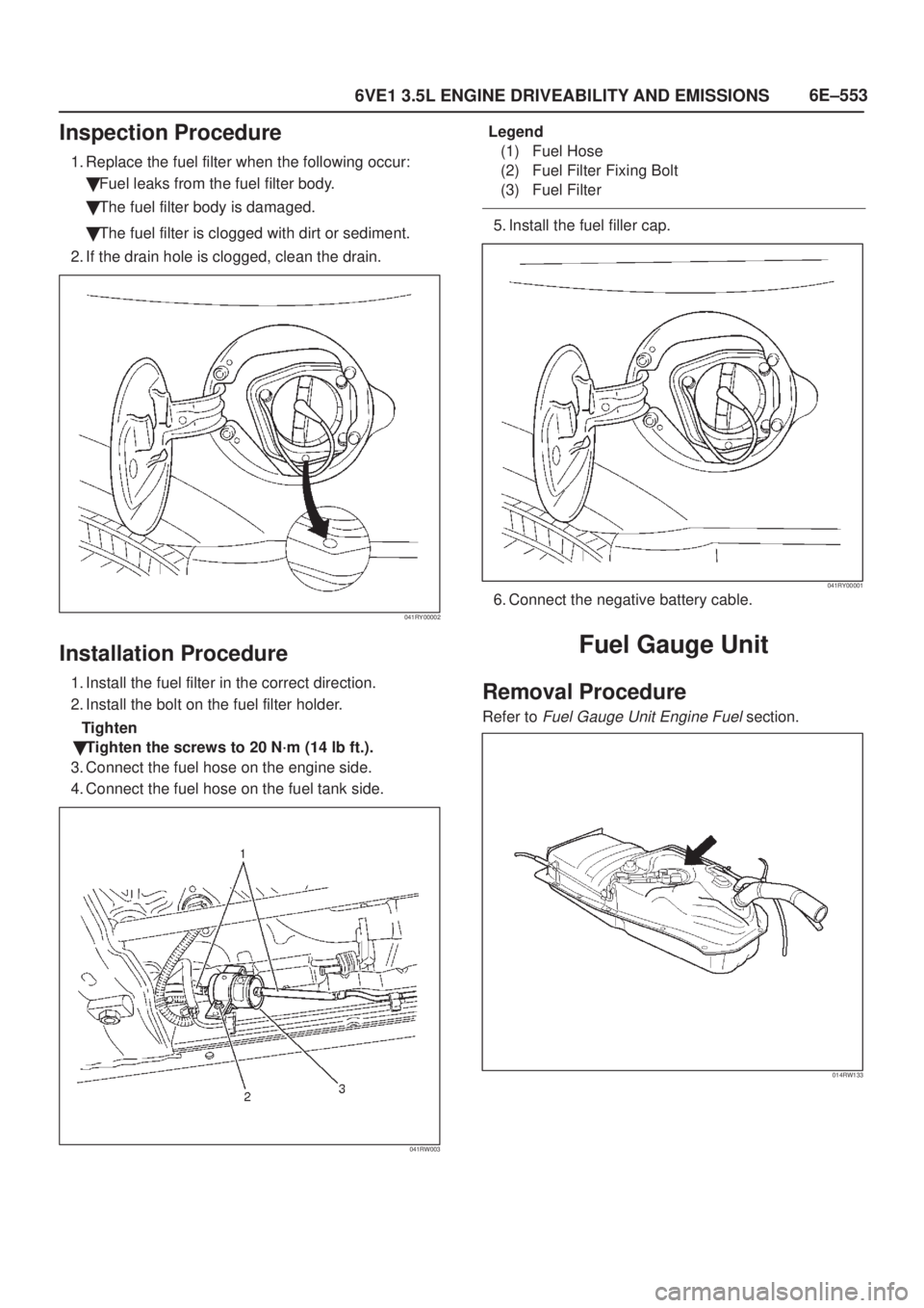
Inspection Procedure
1. Replace the fuel filter when the following occur:
�Fuel leaks from the fuel filter body.
�The fuel filter body is damaged.
�The fuel filter is clogged with dirt or sediment.
2. If the drain hole is clogged, clean the drain.
041RY00002
Installation Procedure
1. Install the fuel filter in the correct direction.
2. Install the bolt on the fuel filter holder.
Tighten
�Tighten the screws to 20 N´m (14 lb ft.).
3. Connect the fuel hose on the engine side.
4. Connect the fuel hose on the fuel tank side.
041RW003
Legend
(1) Fuel Hose
(2) Fuel Filter Fixing Bolt
(3) Fuel Filter
5. Install the fuel filler cap.
041RY00001
6. Connect the negative battery cable.
Fuel Gauge Unit
Removal Procedure
Refer to Fuel Gauge Unit Engine Fuel section.
014RW133
Page 1525 of 2100

6E±558
6VE1 3.5L ENGINE DRIVEABILITY AND EMISSIONS
5. Connect the connectors to manifold absolute
pressure sensor, solenoid valve, electric vacuum
sensing valve.
6. Connect the throttle position sensor electrical
connector to throttle body.
7. Install the engine cover.
8. Connect the negative battery cable.
9. Crank the engine until it starts. Cranking the engine
may take longer than usual due to trapped air in the
fuel rail and in the injectors.
Fuel Tank
Removal Procedure
Refer to Fuel Tank In Fuel Pump Relay
014RW134
Throttle Body (TB)
Removal Procedure
1. Disconnect the negative battery cable.
2. Drain the cooling system. Refer to
Cooling System
section.
3. Disconnect the electrical connectors:
�Throttle position (TP) sensor.
�Intake air temperature (IAT) sensor. Refer to
Intake
Air Temperature Sensor
section.
060RY00014
4. Disconnect the vacuum hose below the air horn.
5. Remove the intake air duct clamp.
6. Disconnect the intake air duct.
7. Disconnect the coolant lines from the throttle body.
8. Remove the bolts from the common chamber.
9. Remove the throttle body from the common chamber.
10. Remove the gasket from the common chamber.
025RY00004
11. Remove the TP sensor. Refer to Throttle Position
(TP) Sensor
section.
Page 1574 of 2100

Oil Pan and Crankcase
Removal
1. Disconnect battery ground cable.
2. Lift vehicle by supporting the frame.
3. Remove under cover.
4. Drain engine oil.
5. Remove fr")
6G±7
ENGINE LUBRICATION (6VE1 3.5L)
Oil Pan and Crankcase
Removal
1. Disconnect battery ground cable.
2. Lift vehicle by supporting the frame.
3. Remove under cover.
4. Drain engine oil.
5. Remove front wheels.
6. Remove oil level dipstick from level gauge tube.
7. Remove radiator under fan shroud.
8. Remove shift on the fly from axle housing.
9. Remove suspension cross member fixing bolts, 2 pcs
each per side and remove suspension cross member.
10. Remove axle housing assembly four fixing bolts from
housing isolator side and mounting bolts from wheel
side. At this time support the axle with a garage jack
and remove axle housing assembly. (for 4y4)
11. Remove the steering unit assembly.
12. Remove starter fixing bolts.
13. Remove oil pan fixing bolts.
14. Remove oil pan, using J-37228 sealer cutter, remove
oil pan.
013RS003
15. Remove crankcase fixing bolts.
16. Remove crankcase, using J-37228 sealer cutter,
remove crankcase.
NOTE: Do not deform or damage the flange of oil pan and
crankcase.
Replace the oil pan and/or crankcase if deformed or dam-
aged.
013RS003
Installation
1. Install crankcase.
A. Remove residual sealant, lubricant and moisture
from mounting surface, then dry thoroughly.
B. Properly apply a 4.5 mm (0.7 in) wide bead of
sealant (TB-1207C or equivalent) to mounting
surface of crankcase.
Sealant bead must be continuous.
�The crankcase must be installed within 5 minutes
after sealant application to prevent premature
hardening of sealant.
013RW010

Fuel Filter
Removal
CAUTION: When repair to the fuel system has been
completed, start engine and check the fuel system
for loose connection or leakage. For the fuel syste")