Page 807 of 1139

Heating and Air Conditioning
Recirculation Control Motor Test
1. Disconnect the 5P connector from the recirculation
control motor.
Incorrectly applying power and ground to
the recirculation control motor will damge it.
Follow the instructions carefullv.
2. Connect batterv oower to the No. 5 terminal ofthe
recirculation control motor, and ground the No. 1
and No. 2 terminals; the recirculation control motor
should run smoothly. To avoid damaging the
recirculation control motor, do not reverse power
and ground. Disconnect the No. 1 or No. 2
terminals from ground; the recirculation control
motor should stop at Fresh or Recirculate. Don't
cycle the recirculation control motor {or a long time.
RECIRCULATION CONTROL MOTOR
lf the recirculation control motor does not run in
step 2, remove it, then check the recirculation
control linkage and doors for smooth movement.
. lfthe linkage and doors move smoothly, replace
the recirculation control motor.. lf the linkageordoorsstickor bind, repairthem
as neeoeo.
21-36
Recirculation Control MotorI
Replacement
1.Remove the ECM (see page 11-4).
Remove the relay mount bracket bolt. and move
the relays out of the way,
Disconnect the 5P connector (A) from the
recirculation control motor (B), Remove the self-
tapping screws and the recirculation control motor
from the blower unit.
Installthe motor in the reverse order of removal.
Make sure the pin on the motor is properly
engaged with the linkage. After installation. make
sure the motor runs smoothly.
\
Page 815 of 1139

Heating and Air Conditioning
Heater Unit/Core Replacement (cont'd)
8. Remove the dashboard {see page 20-66).
9. Disconnectthe connectors (A) from the blower
motor, the recirculation control motor, the mode
control motor, and the power transistor, then
remove the wire harness clips (B) and the
connector (C). Remove the self-tapping screws and
the bracket (D).
Disconnect the connectors (A) from the evaporator
temperature sensor and the air mix control motor,
then remove the wire harness clips (B) and the
connector (C). Remove the self-tapping screw and
the cover (D). Disconnect the heater valve cable (E).
10,
7t,
21-44
11. Remove the mounting bolts, the mounting nuts,
and the heater unit.
Remove the self-tapping screws and the expansion
valve cover (A). Carefully pull out the evaporator
core (B) so you don't bend the inlet and outlet pipes.
Remove the grommet (C), then remove the self-
tapping screws and the flange cover (D). Bemove
the self-tapping screws and the pipe cover (E), then
carefully pull out the heater core (F) so you don't
bend the inlet and outlet oioes.
@
5x 1.0 mm9.8 N.m11.0 kgl m,7.2 tbf.ftl
12.
Page 817 of 1139
Heating and Air Conditioning
Heater Valve Cable Adjustment
1. From underthe hood, open the cable clamp {A),
then disconnect the heater valve cable (B) from the
heater valve arm {C).
tFrom under the dash, disconnect the heater valve
cable housing from the cable clamp (A), and
disconnect the heater valve cable (B) from the air
mix control linkage {C).
, t.- l
\'r2t' ''' '
' ::"'
Set the temperature control dial on Max Cool with
the ignition switch ON (ll).
Attach the heater valve cable (B) to the air mix
control linkage (C) as shown above, then snap the
heater valve cable housing into the cable clamp (A).
.'.-:',,
-"ll
.....-
21-46
5, From under the hood, turn the heater valve arm {C)
to the fully closed position as shown, and hold it.
Attach the heater valve cable (B) to the heater valve
arm, and gently pull on the heater valve cable
housing to take up any slack, then install the heater
valve cable housing into the cable clamp (A).
.
\
Page 818 of 1139

Compressor Replacement
1. lf the compressor is marginally operable, run the
engine at idle speed, and let the air conditioning
work for a few minutes, then shut the engine off.
2. Make sure you have the anti-theft code for the radio,
then write down the frequencies for the radio's
preset buttons.
3. Disconnect the negative cable from the battery.
4. Recover the refrigerant with a recovery/recycling/
charging station (see page 21-53).
5. Remove the alternator (see page 4-29).
6. Remove the Ay'C condenser fan assembly (see page
10-10).
7. Disconnectthe compressor clutch connector (A),
remove the bolts, then disconnect the suction line(B) and the discharge line (C)from the compressor.
Plug or cap the lines immediately after
disconnecting them to avoid moisture and dust
contamination.
6 x '1.0 mm9.8 N.m11.0 kgt.m,7.2 tbl.ttl
u1/
(
o
8. Remove the mounting bolts and the compressor.
8 x 1.25 mm22 N.m 12.2 kgf.m.
9. Installthe compressor in the reverse order of
removal, and note these items:
. Before installing the new compressor, check for
metal or other contamination in the line. Replace
any contaminated parts.. lf you're installing a newcompressor, you must
calculate the amount of refrigerant oil to be
removed from it (see page 21-6).. Replace the O-rings with new ones at each fitting,
and apply a thin coat of refrigerant oil before
installing them. Be sure to use the correct O-rings
for HFC-134a {R-134a) to avoid leakage,. Use refrigerant oil (KElHlN SP-'10) for HFC-134a
KEIHIN spiral type compressor only.. To avoid contaminatlon, do not return the oilto
the container once dispensed, and never mix it
with other refrigerant oils.. lmmediately after using the oil, reinstallthe cap
on the container, and seal it to avoid moisture
absorption.. Do not spill the refrigerant oil on the vehicle; it
may damage the paint. lf the refrlgerant oil
contacts the paint, wash it off immediately.. Charge the system (see page 21-55).. Do the engine control module (ECM) idle learn
procedure (see page 11-'139).. Enter the antitheft code for the radio, then enter
the customer's radio station presets.
21-47
Page 823 of 1139

Heating and Air Conditioning
Gondenser Replacement
1.
6x1.0mm9.8 N.m ('1.0 kgf.m,7.2lbf.ft)
Recover the refrigerant with a recovery/recycling/
charging station (see page 21-53).
Remove the front bumper {see page 20-85).
Remove the bolts, then disconnect the discharge
line (A) and the condenser line (B) from the
condenser. Plug or cap the lines immediately after
disconnecting them to avoid moisture and dust
conlamtnaflon.
,t\
6x1.0mm9.8 N.m (1.0 kgt.m.7.2lbf.ft)
21-52
4, Remove the mounting bolts, then remove the
condenser by lifting it up. Be careful not to damage
the radiator or the condenser fins when removino
the condenser.
6 x '1.0 mm9.8 N.m ('1.0 kgf.m,7.2 tbl.ftl
5.lnstallthe condenser in the reverse order of
removal, and note these items.
. lf you're installing a newcondenser, add
refrigerant oil (KElHlN SP- 10) lsee page 21'6).. Replace the O-rings with new ones at each fitting,
and apply a thin coat of refrigerant oil before
installing them. Be sure to use the correct O-rings
for HFC-134a (R-'134a)to avoid leakage.. lmmediately after using the oil, reinstallthe cap
on the container, and seal it to avoid moisture
absorption.. Do not spillthe refrigerant oil onthevehicle;it
may damage the paint. lf the refrigerant oil
contacts the paint, wash it off immediately.. Be careful not to damage the radiator or the
condenser fins when installing the condenser.. Charge the system (see page 21-55).
t -"'.
f,
t-
-li .:)-:.-- ---- - -'
Page 824 of 1139

Refrigerant Recovery
Air conditioning refrigerant or lubricant vapor
can irritate your eyes, nose. or throat.
Be careful when connecting service equipment.
Do not breathe refrigerant or vapor
Use only service equipment that is U.L.-listed and is
certified to meet the requirements of SAE J2210 to
remove HFC-134a (R-134a) from the air conditioning
system.
lf accidental system discharge occurs, ventilate the
work area before resuming service
Additional health and safety information may be
obtained from the refrigerant and lubricant
manufacturers.
1!l r: i t: -:
-'', -
-
(
'=i
r
1. Connect a R-134a refrigerant recovery/recycling/
charging station {A) to the high-pressure service
port (B) and the low-pressure service port (C), as
shown, following the equipment manufacturer's
instructions.
lvleasure the amount of refrigerant oil removed
from the Ay'C system after the recovery process is
completed. Be sure to put the same amount of new
refrigerant oil back into the Ay'C system before
chargrng.
21-53
Page 825 of 1139

Heating and Air Conditioning
System Evacuation
Use only service equipment that is U.L.-listed and is
certified to meet the requirements of SAE J2210 to
remove HFC-134a (R-134a)from the air conditioninq
system.
lf accidental system discharge occurs, ventilate the
work area before resuming service.
Additional health and safety information may be
obtained from the refrigerant and lubricant
manufacturers.
1. When an Ay'C system has been opened to the
atmosphere, such as during installation or repair, it
must be evacuated using a R-134a refrigerant
recovery/recycling/charging station (lf the system
has been open for several days, the receiver/dryer
should be replaced, and the system should be
evacuated for several hours.)
. Air conditioning refrigerant or lubricant vapor
can irritate your eyes, nose, or throat.. Be carefulwhen connecting service equipment.. Do not breathe refrigerant or vapor.
21-54
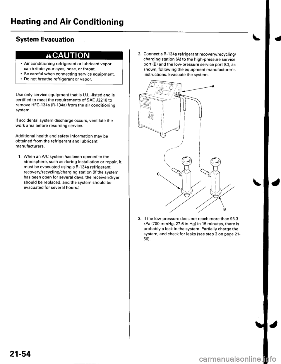
2. Connect a R-134a refrigerant recovery/recycling/
charging station (A)to the high-pressure servicepon (B) and the low-pressure service port (C), as
shown, following the equipment manufacturer's
instructions. Evacuate the system.
lf the low-pressure does not reach more than 93.3
kPa {700 mmHg, 27.6 in.Hg) in 15 minutes, there isprobably a leak in the system. Partially charge the
system, and check for leaks (see step 3 on page 21-
56).
-i - r4.t
Page 826 of 1139

System Charging
Air conditioning refrigerant or lubricant vapor
can irritate your eyes, nose, or throat.
Be carefulwhen connecting service equipment.
Do not breathe refrigerant or vapor,
Use only service equipment that is U.L.'listed and is
certified to meet the requirements of SAE J2210 to
remove HFC-134a {R-134a) from the air conditioning
system.
lf accidental system discharge occurs, ventilate the
work area before resuming service
Additional health and safety information may be
obtained from the refrigerant and lubricant
manufacturers.
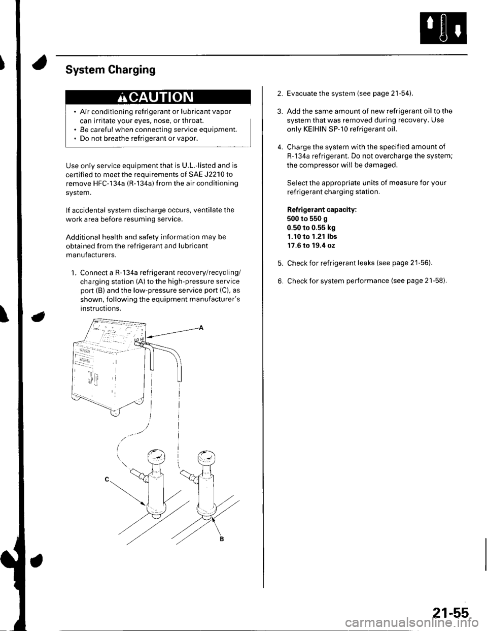
1. Connect a R-134a refrigerant recovery/recycling/
charging station (A) to the high-pressure service
pon (B) and the low-pressure service port {C), as
shown, following the equipment manufacturer's
instructions.
2.
3.
4.
Evacuate the system (see page 21'54).
Add the same amount of new refrigerant oil to the
system that was removed during recovery. Use
only KEIHIN SP-10 refrigerant oil.
Charge the system with the specified amount of
R-134a refrigerant. Do not overcharge the system;
the compressor will be damaged.
Select the appropriate units of measure for your
refrigerant charging station.
Refrigerant capacity:
500 to 550 g
0.50 to 0.55 kg
1.10 to 1.21 lbs
17.6 to 19.4 oz
Check for refrigerant leaks (see page 21'56).
Check for system performance (see page 21-58).
21-55