2002 HONDA CIVIC dead battery
[x] Cancel search: dead batteryPage 57 of 1139

Gharging System
Charging Circuit Troubleshooting
lf the charging system indicator does not come on or
does not go off, or the battery is dead or low, test these
items in the order listed below:
Battery (see page 22-50)
Charging system indicator
Alternator and regulator circuit
Alternator control system
Charging System Indicator Test
1. Turn the ignition switch ON {ll).
Does the chatging system indicator come on?
YES Go to step 2.
NO Go to step 3.
2. Start the engine.
Does the charging system indicator go off?
YES-Charging system indicator circuit is OK. Go
to the Alternator and Regulator circuit Test. t
NO-Go to step 3.
3. Turn the ignition switch OFF.
4. Troubleshoot the multiplex control system (see
page 22 172).
ls the multiplex control system OK?
YES Go to step 5.
NO Check the multiplex control system as
indicated by the diagnostic trouble code (DTC) (see
step 8 on page 22-172).1
5. Disconnect the engine wire harness 6P connector
from the starter sub harness 6P connector.
4-22
\"4
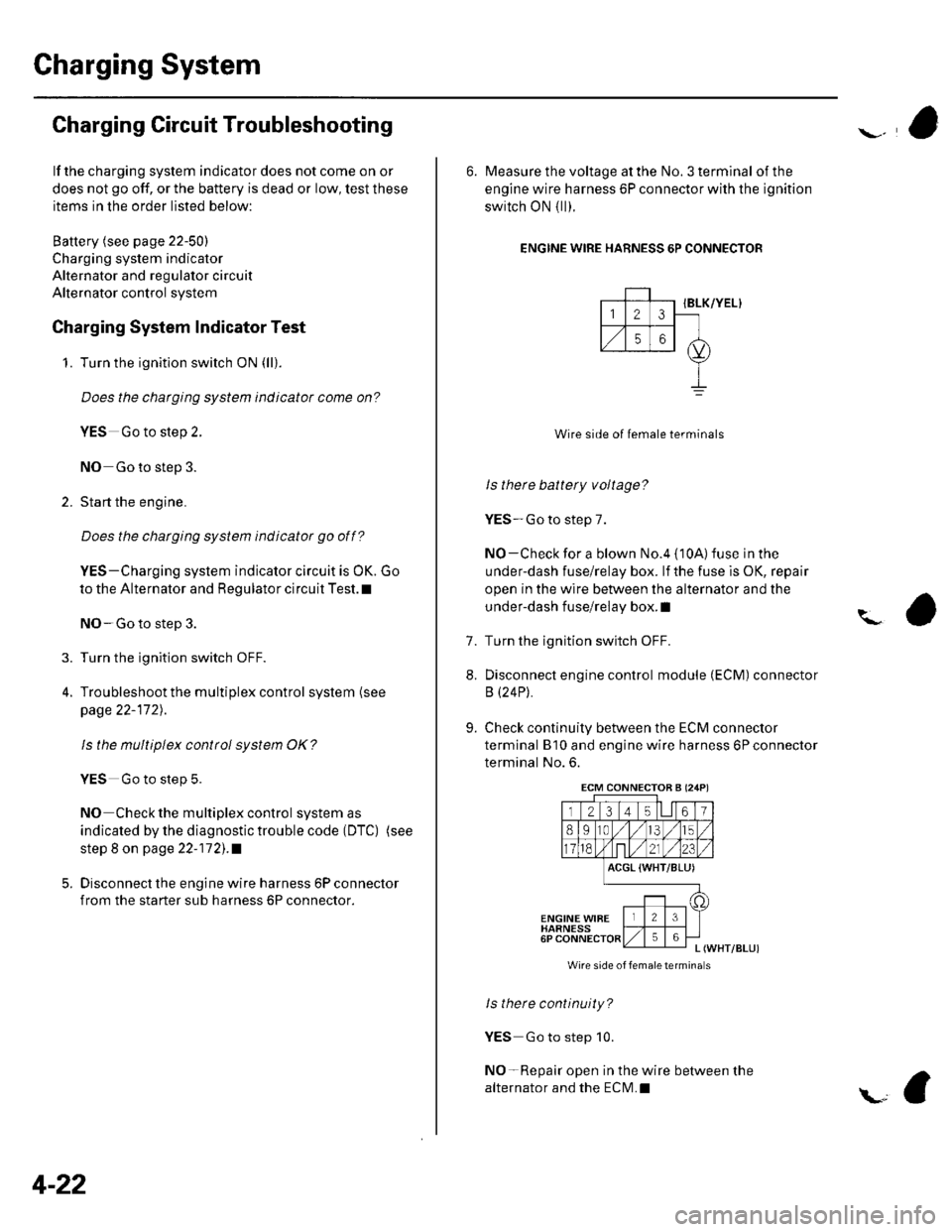
6. Measure the voltage at the No. 3 terminal of the
engine wire harness 6P connector with the ignition
switch ON { ll).
ENGINE WIRE HARNESS 6P CONNECTOR
IBLK/YEL}
Wire side of female terminals
ls there battery voltage?
YES-Go to step 7.
NO-Check for a blown No.4 {10A) fuse in the
under-dash fuse/relay box. lf the fuse is OK, repair
open in the wire between the alternator and the
under-dash fuse/relay box. I
Turn the ignition switch OFF.
Disconnect engine control module (ECM) connector
B (24P).
Check continuity between the ECM connector
terminal B'10 and engine wire harness 6P connector
terminal No. 6.
?
7.
8.
9.
ACGL {WHT/BLU)
ENGINE WIBEHARNESS6PL (WHT/BLUI
Wire side of femaletermina s
ls there continuity?
YES Go to step 10.
NO-Repair open in the wire between the
alternator and the ECN4.I
ECM CONNECTOB A (24P)
Page 227 of 1139
![HONDA CIVIC 2002 7.G Workshop Manual Fuel and Emissions Systems
System Descriptions {contd)
ECM Inputs and Outputs at Connector A (31P)
\. il
Wire side of female terminals
\.
1AFS]TC2
GP2
3IGPl4PG25PG.16AFS+1
CKP
IKS
10SG211sG1
12IACV
HONDA CIVIC 2002 7.G Workshop Manual Fuel and Emissions Systems
System Descriptions {contd)
ECM Inputs and Outputs at Connector A (31P)
\. il
Wire side of female terminals
\.
1AFS]TC2
GP2
3IGPl4PG25PG.16AFS+1
CKP
IKS
10SG211sG1
12IACV](/manual-img/13/5744/w960_5744-226.png)
Fuel and Emissions Systems
System Descriptions {cont'd)
ECM Inputs and Outputs at Connector A (31P)
\. il
Wire side of female terminals
\.
1AFS]TC2
GP2
3IGPl4PG25PG.16AFS+1
CKP
IKS
10SG211sG1
12IACV
'15
TPS16AFS_18
VSS
19IVAP20vcc221vccl
22AFSHTC+
23LG225
Ct\.4PA
26CMPB(rDc)
27IGPLS428IGPLS329IGPLS230IGPLS,I
NOTE: Standard battery voltage is 12 V.
JorminalnumberWirecolor[€rminal namoDescriptionSignal
19GRN/REDMAP (MANIFOLDABSOLUTE PRESSURESENSOR)
Detects MAP sensor signalWith ignition switch ON (ll):about3 VAt idle: about 1.0 V (depending on enginespeed)
20YEUBLUVCC2 (SENSOR VOLTAGE)Provides sensor voltageWith ignition switch ON {ll): about 5 VWith ionition switch OFF: about0V21YEUREDVCC] (SENSOB VOLTAGE)Provides sensor voltageWith ignition switch ON {ll): about 5 VWith ionition switch OFF: about0V22AFSHTC - (AIR FUELRATIO (A"iFiSENSORHEATER CONTROL + SIDE)
Detects a,/F sensor heatervoltageWith ign;tion switch ON lll): banery voltage
23BRN?ryE LLG2 (LOGIC GROUNDround for the ECM circuLessthan 1.0 V at alltimes24BRN?ryE L1(Lround for the ECM circuLess than '1.0 V at alltimes25B LU,^/VHTCMP A (CAMSHAFT
POSITION SENSOR A)Detects CMP sensor AstonalWith engine running: pulses
26GRNCMP B CAMSHAFTPOSITION (CMP)SENSOBB (TDC (TOP DEAD CENTERSENSORi)
Detects CMP sensor 8 (TDc
sensor)With engine running: pulses
27BRNIGPLS4 {No. 4IGNITIONCOIL PULSE)Drives No, 4 ignition coiWith ignition switch ON (ll)r about 0 vWith engine running: pulses28WHT/BLUIGPLS3 {No.3IGNITIONCOIL PULSE)Orives No.3 rgnition coi
29BLU/REDlGPLS2lNo.2 IGNITIONCOIL PTJLSE)Drives No.2 ignition coil
30YEUGRNIGPLSI (No. 1 IGNITIONco
PlltsF)Drives No. I ignition coil
11-20
\.
a
a
Page 253 of 1139

Fuel and Emissions Systems
How to Set Readiness Codes
Malfunction lndicator Lamp (MlL) Indication
(ln relation to Readiness Codesl
The vehicle has certain "readiness codes" that are part
of the on-board diagnostics for the emissions systems.
lf the vehicle's battery has been disconnected or gone
dead, if the DTCS have been cleared, or if the ECM has
been reset, these codes are set to incomplete. In some
states, part of the emission testing is to make su re these
codes are set to complete. lf all of them are not set to
complete, the vehicle may fail the emission test, or the
test cannot be finished.
To check ifthe readiness codes are complete, turn the
ignition switch ON (ll), but do not start the engine. The
MIL will come on for 15 20 seconds. lf it then goes off,
the readiness codes are complete. lf it blinks several
times, one or more readiness codes are not complete.
To set readlness codes from incomplete to complete.
do the procedure for the appropriate code.
11-46
L
Catalytic Converter Monitor and Readiness
Code
NOTE:. Do not turn the ignition switch off during the
procedure.
. All readiness codes are cleared when the battery is
disconnected or when the ECM is cleared with the
OBD ll scan tool or Honda PG lvl Tester.. Low ambient temperatures or excessive slop-and-go
traffic may increase the drive time needed to switch
the readiness code from incomplete to complete.' The readiness code will not switch to com Dlete until
all the enable criteria are met.. lf a fault in the secondary HO2S system caused the
MIL to come on. the readiness code cannot be set to
comDlete until vou correct the fault.
Enable Criteria. ECT at 158"F (70'C) or higher.. Intake air temperature (lAT) at 20"F (-7'C) or higher.. Vehicle speed is steady, and vehicle speed sensor
(VSS) reads more then 25 mph (13km/h).
Procedure
1. Connect the scan tool to the vehicle's data link \
connector (DLCi, and bring up the tool's generic \"
OBD ll mode.
Start the engine.
Test-drive the vehicle under stop-and-go conditions
with short periods of steady cruise. After about
5 miles (3 km), the readiness code should switch
from incomplete to complete.
lf the readiness code is still set to incomplete, check
for a temporary DTC. lf there is no DTC, one or
more of the enable crlteria were probably not met;
2.
3.
Page 1030 of 1139

General Troubleshooting Information
DTC (Diagnostic Trouble Codesl
The self-diagnostic function of the SRS system allows it
to locate the causes of system problems and then store
this information in memory. For easier troubleshooting,
this data can be retrieved via a data link circuit.
. When you turn the ignition switch ON (ll), the SRS
indicator will come on. lf it goes off after 6 seconds,
the system is normal.. lf there is an abnormality, the svstem locates and
defines the problem, stores this information in
memory, and turns the SRS indicator on. The data
will remain in the memory even when the ignition
switch is turned off or if the battery is disconnected.. When you connect the Honda PG lM Tester to the 16P
data link connector (DLC)to short the SCS terminal,
and turn the ignition switch ON (ll). the SRS indicator
will indicate the diagnostic trouble code (DTC) by the
number of blinks.. When you connect the Honda PGM Tester to the 16P
data link Connector (DLC), you can retrieve the DTC in
the Honda Systems "SRS" menu.. After reading and recording the DTC, proceed with
the troubleshooting procedure for th is code.
Precautions. Use only a digital multimeter to check the system. lf
it's not a Honda multimeter, make sure its output is
10 mA (0.01A) or less when switched to the smallest
value in the ohmmeter range, A tester with a higher
output could damage the airbag circuit or cause
accidental airbag deployment and possible injury.. Whenever the ignition switch is ON (ll), or has been
turned OFF for less than 3 minutes, be careful not to
bump the SRS uniU the airbags could accidentally
deploy and cause damage or injuries.. Before you remove the SRS harness, disconnect the
driver's airbag connector. the front passenger's
airbag connector, both side airbag connectors, both
seat belt buckle tensioner connectors, and both seat
belt tensioner connectors.. Make sure the battery is sufficiently charged. lf the
battery is dead or low, measuring values won't be
correct.. Do not touch a tester probe to the terminals in the
SRS unit or harness connectors, and do not connect
the terminals with a jumper wire. Use only the
backprobe set and the Honda PGM Tester. Backprobe
spring loaded lock type connectors correctly.
Reading the DTC
When the SRS indicator is on, read the DTC using either
of the following methods:
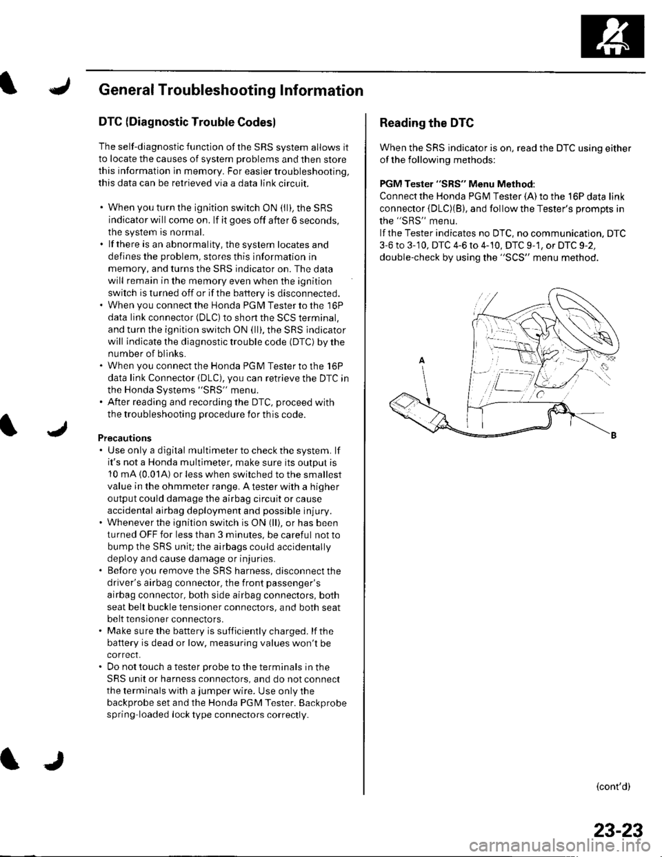
PGM Tester "SRS" Menu Method:
Connect the Honda PGM Tester {A) to the 16P data link
connector {DLC)(B), and follow the Tester's Drompts in
the "SRS" menu.
lf the Tester indicates no DTC, no communication. DTC
3-6 to 3-'10, DTC 4-6 to 4-10, DTC 9-1, or DTC 9-2,
double-check by using the "SCS" menu method.
(cont'd)
23-23