2002 HONDA CIVIC air condition
[x] Cancel search: air conditionPage 827 of 1139

Heating and Air Conditioning
Refrigerant Leak Test
Special Tool Required
Leak detector, Honda Tool and Equipment YGK-H-10PM
commerciallv available
Compressed air mixed with R-134a forms a
combustible vapor.
The vapor can burn or explode causing serious
injury.
Never use compressed air to pressure test
R-134a service equipment or vehicle air
conditioning system.
Air conditioning refrigerant or lubricant vapor
can irritate your eyes, nose, or throat.
Be carefulwhen connecting service equipment.
Do not breathe refrigerant or vapor
Use only service equipment that is U.L.-listed and is
certiified to meet the requirements of SAE J2210 to
remove HFC-134a (R-134a) from the air conditioning
system.
lf accidental system discharge occurs, ventilate the
work area before resuming service.
R-134a service equipment or vehicle air conditioning
systems should not be pressure tested or leak tested
with compressed air.
Additional health and safety information may be
obtained from the refrigerant and lubricant
manufacturers.
21-56
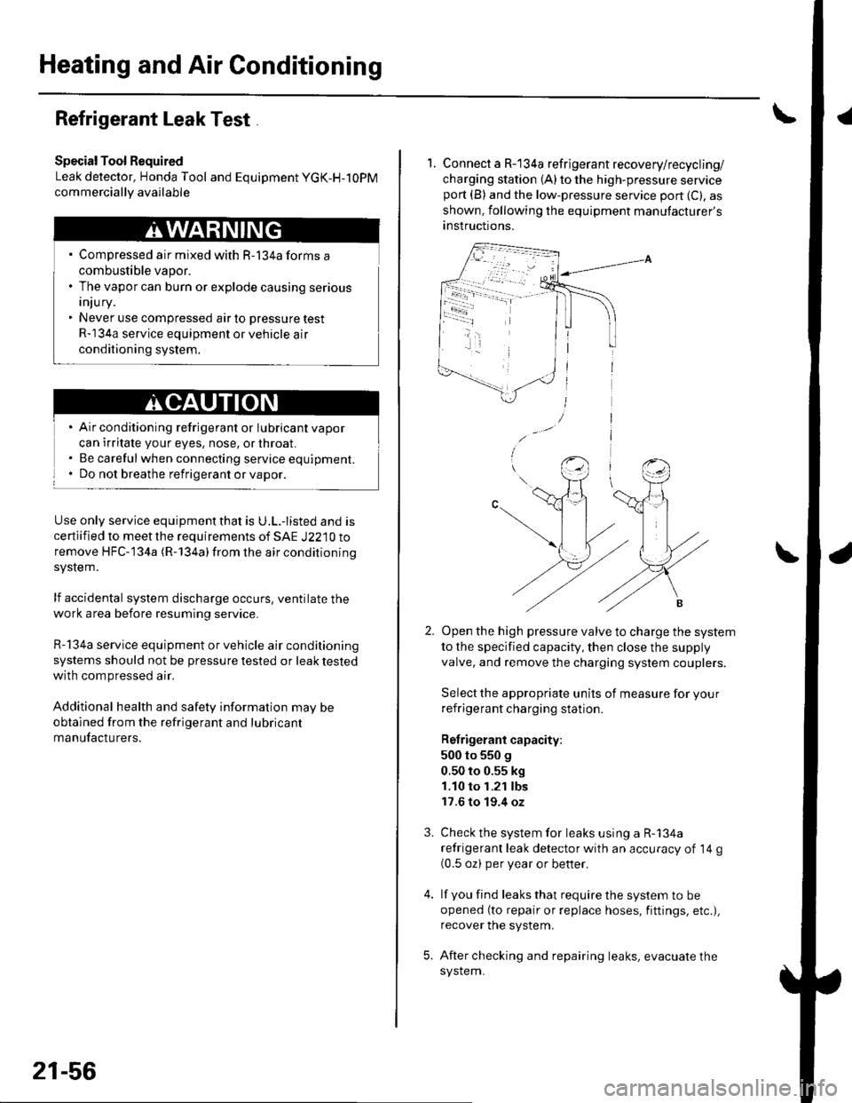
1. Connect a R-134a refrigerant recovery/recycling/
charging station (A) to the high-pressure serviceport (B) and the low-pressure service port (C), as
shown, following the equipment manufacturer's
anstructions.
Open the high pressure valve to charge the system
to the specified capacity, then close the supply
valve, and remove the charging system couplers.
Select the appropriate units of measure for your
refrigerant charging station.
Refrigerant capacity:
500 to 550 g
0.50 to 0.55 kg
1.10 to 1.21 lbs
17.6 to 19.4 oz
Check the system for leaks using a R-134a
refrigerant leak detector with an accuracy of 14 g(0.5 oz) per year or better.
lf you find leaks that require the system to be
opened (to repair or replace hoses, fittings, etc.),
recover the system.
After checking and repairing leaks, evacuate the
system.
3.
Page 829 of 1139

Heating and Air Conditioning
A/C System Tests (cont'd)
1.
Performance Test
Air conditioning refrigerant or lubricant vapor
can irritate your eyes, nose, or throar.
Be carefulwhen connecting service equipment.
Do not breathe refrigerant or vapor.
The performance test will help determine if the air
conditioner system is operating within specifications.
Use only service equipment that is U.L.-listed and is
cenified to meet the requirements of SAE J2210 toremove HFC-134a (R-134alfrom the air conditioning
system.
lf accidental system discharge occurs, ventilate the
work area before resuming service
R-134a service equipment or vehicle air conditioning
systems should not be pressure tested or leak testedwith compressed air.
Additional health and safety information may be
obtained from the refrigerant and lubricant
manufacturers.
Connect a R-134a refrigerant recover/recycling/
charging station to the high-pressure service port
and the low-pressure service port, following the
equipment manufacturer's instructions.
Determine the relative humidity and air
Iemperaru re.
' Compressed air mixed with R-134a forms a
combustible vapor.. The vapor can burn or explode causing serious
Injury.. Never use compressed air to pressure test
R-134a service equipment or vehicle air
conditioning systems.
21-58
4.
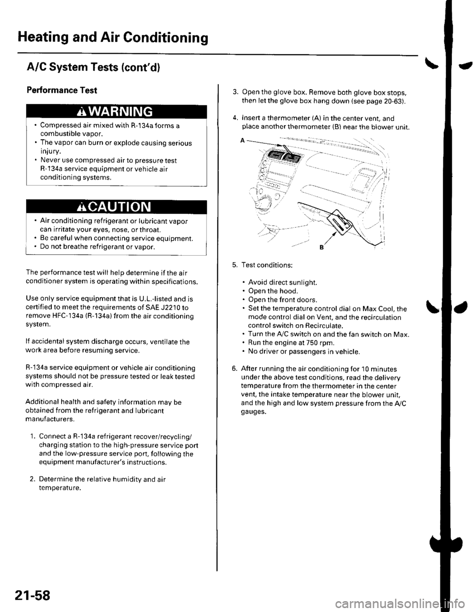
Open the glove box. Remove both glove box stops,
then let the glove box hang down (see page 20-63).
Insert a thermometer (A) in the center vent, andplace another thermometer {B) near the blower unit.
Test conditions:
. Avoid direct sunlight.. Open the hood.. Open the front doors.. Sel the temperature control dial on Max Cool, the
mode control dial on Vent, and the recirculation
control switch on Recirculate.. Turn the A,/C switch on and the fan switch on Max.. Run the engine at 750 rpm.. No driver or passengers in vehicle.
After running the air conditioning for I0 minutes
under the above test conditjons, read the delivery
temperature from the thermometer in the center
vent, the intake temperature near the blower unit,
and the high and low system pressure from the Ay'Cga uges.
Page 918 of 1139

Turn Signal/Hazard Relay Input Test
1. Removetheturn signal/hazard relay (A) from the under-dash fuse/relay box (B).
Inspect the relay and fuse/relay box socket terminals to be sure they are all making good contact
. lf the terminals are bent. loose, or corroded, repairthem as necessary, and recheckthe system.
. lf the terminals look OK, go to step 3.
Make these input tests at the fuse/relay box.
.lfanvtestindicatesaproblem,findandcorrectthecause,thenrecheckthesystem.
. lf all the inputtests prove OK,theturn signal/hazard relay must befaulty. Replace it
000i 0!1000
00u! u0
CavitvTesl conditionTest: Desired resultPossible cause il result is not obtained
1Under all conditionsCheck for continuity to ground:
There should be continuiw.
. Poor ground (G201)
. An ooen in the wire
3lgnition switch ON ( ll)
Hazard warning switch
OFF
Check for voltage to ground:
There should be battery voltage.
' Blown No. 19 (7.5A) fuse in the
under-dash fuse/relay box. Faulty hazard warning switch. An ooen in the wire
Hazard warning switch
ON
lgnition switch OFF
Check for voltage to ground:
There should be battery voltage.
. Blown No. 5 {10A) fuse in the
under-hood fuse/relay box. Faulty hazard warning switch. An ooen in the wire
2lgnition switch ON ( ll)
and turn signal switch
in Right or Left position
Connect No. 2 terminalto No. 3
terminal:
Right or left turn signal lights
should come on.
. Poor ground (G201, G301, G501,
G502, G553). Faulty turn signal switch. An oDen in the wire
lgnition switch OFF
Hazard warning switch
ON
Connect No.2 terminal to No. 3
termrnal:
Hazard wa rning lights should
come on.
. Poor ground (G201, G301, G501,
G502, G553). Faulty hazard warning switch. An open in lhe wire
22-87
Page 961 of 1139

Power Windows
1.
2.
Passenger's Window Switch Input Test
Remove the switch panel (see page 20-4).
Disconnect the 5P connector (A) from the switch (B).
o
'' "'"1.
4.
Wire side of female terminals
BLU/WHTGRN/BLK
Input the connector and socket terminals to be sure they are all making good contact.
. lf theterminals are bent, loose or corroded, repairthem as necessary, and recheckthe system.. lf the terminals look OK, go to step 4.
Reconnect the connector, and using a back probe, make these input tests at the connector. lf any test indicates aproblem, find and correct the cause, then recheck the svstem,
CavitvWireTest conditionTest: Desired resultPossible cause if result is not obtained
3GRN/BLKlgnition switch ON
{ ll)
Check for voltage to
grouno:
There should be battery
voltage.
Blown No.6 (7,5A)fuse in the
under-dash fuse/relay box
Blown No.22 {20A)fuse in the
under-dash fuse/relay box
Faulty power window relay
An open in the wire
Poor qround (G201)
2BLD,A/VHTlgnition switch ON( )
At the master
window switch,
press and hold
down the
passenger's switch
Check for voltage to
ground:
There should be battery
voltage.
Faulty master window switch
An open in the wire
BLU/REDlgnition switch ON(||)
At the master
window switch,
pull up and hold
the passenger's
switch
Check for voltage to
grouno:
There should be battery
voltage.
Faulty master window switch
An open in the wire
22-130
Page 1007 of 1139

Multiplex Control System
Multiplex Control Unit lnput Test (cont'd)
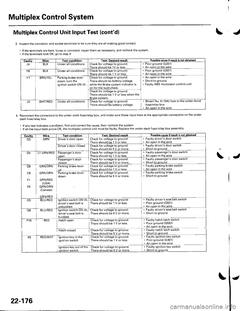
3. Inspect the connector and socket terminals to be sure they are all making good contact
.lftheterminalsarebent,looseorcorroded,repairthemasnecessary,andrecheckthesystem. llthe terminals look OK, go to step 4.
4. Reconnectthe connectorstothe under dash fuserelay box, and make surethese inputtests atthe appropriate connectors on lhe under-
dash fuse/relav box.
. lf any test indicates a problem, {ind and correct the cause, then recheck the system. lf allthe input tests prove OK, the multiplex control unit must be faulty. Replace the under_dash fuse/relay box assembly
CavitvWireTest conditionTest: Desired .esult r Possible cause if resullE qS!q!!e!!ed
J4BLK[J nder all conditionsCheck {or voltage 1o ground:Therc sholl.l he 1V or lessPoor ground (G20'l)An ooen in the wire
Y6BLKlJnder all conditionsCheck for voltage to ground:There should bc 1 V or less.Poor ground 1G501)An ooen in the wire
Y1BFNryELParking brake leverdown, turn theigntion switch ON (ll)
Check for voltage to ground:There should be battery voltagewhile the Brake system indicator ison forthe buld check.
An open in the wireShortto groundFaulty ABS modulatorcontrol unit
Check for voltage to ground:There should be 1V or less when the
J2WHT/REDUnder allconditionsCheck for voltage to groundiThere should be baftery voltage.Blown No.9 (10A)fuse in the under'hoodfuse/relay boxAn oncn in rhc wire
CavitvTest conditionTesi: Oesired resultPossible cause ifresult is notobtained
o3GRNDriver's door openCheck for voltage to ground:There should be 1 V or less-Faulty driver's door switchAn ooen in the wire
Driver's door closedCheck for voltage to ground:There should be 5 V or more.Faulty driver's door switchShort to qround
O4LT GRN/REDPassenger's doorCheck .for voltage 10 ground:There should be 1 V or less.Faulty passenger's door switchAn ooen inthewire
Passenger's doorCheck for voltage to ground:There should be 5 V or more.Faulty passenger's door switchShort to oround
osI]l.l
4.,
F1
F8
GRN/ORN
GRN/ORN
GRN/RED(USA)GRN/ORN(Canada)
Parking brake leverCheck for voltage to groLrnd:There shorl.l be 1 V or less.Faulty parking brake switch. An ooen in thewireCheck for voltage to ground:There should be 5 V or more.
. Faulty parking brake switchShortto ground
o5BLU/REDlgnition switch ON (ll),
driver's seat belt isCheck for voltage to ground:There should be 1V or less.Faulty driver's seat belt switchPoorground (G551)An oDen in the wire
Q6BLU/REDlgnition switch ON (ll)
driver's seat belt isbuckled.
Check {or voltage to ground:There should be 6 V or more.Faulty driver's seat belt switchShortto ground
P18RED
H",=
Check for voltage to ground:There sho0ld be 1V or less-
f -9*:li:'^:**:':s*:*
Faulty hatch latch swrtchPoor ground (G552)An open in the wireFaulty hatch latch switch
X5lgnirion key in the Check for voliage to gtound:ignit on switch Thpre should be I V or lcss
lgnrtron kev our o{ the Check for vollage to ground:
. Faulty ignition key switch. Poor ground (G401). An open in the wire
I : [11y.'::i':::1"' **6
\
22-176