2002 HONDA CIVIC heater
[x] Cancel search: heaterPage 229 of 1139
![HONDA CIVIC 2002 7.G Workshop Manual Fuel and Emissions Systems
System Descriptions (contdl
ECM lnputs and Outputs at Connector E (31P}
L
u
1iMoFPR
2sr-{]zs3LG34SG3
6$1025HTC
1M RLY
8AFSHTCR
I
14FTP15ELD
16EPSLD
18ACC20Z/VBS21VSV
22BKSW HONDA CIVIC 2002 7.G Workshop Manual Fuel and Emissions Systems
System Descriptions (contdl
ECM lnputs and Outputs at Connector E (31P}
L
u
1iMoFPR
2sr-{]zs3LG34SG3
6$1025HTC
1M RLY
8AFSHTCR
I
14FTP15ELD
16EPSLD
18ACC20Z/VBS21VSV
22BKSW](/manual-img/13/5744/w960_5744-228.png)
Fuel and Emissions Systems
System Descriptions (cont'dl
ECM lnputs and Outputs at Connector E (31P}
L
u
1iMoFPR
2sr-{]zs3LG34SG3
6$1025HTC
1M RLY
8AFSHTCR
I
14FTP15ELD
16EPSLD
18ACC20Z/VBS21VSV
22BKSW23K-LINE24SEFMJ26NEP
21rMoCD
29scs30WEN31MIL
Wire side of female terminals
NOTE: Standard battery voltage is '12 V.
TerminalnumberWire colorferminal nameDescription Signal
GRNI/ELIMO FPR (IMMOBILIZERFLJEL PUMP RELAYIDrives PGM Fl main relay 20Vfor2 seconds after turning ignition switch ON{ll). then batterv voltaoe2WHT/REDSHO2S (SECONDARYHEATED OXYGEN SENSOR(SECONDARY HO2S),SENSOR 2r
Detects secondary HO2S{sensor 2) signalWith throttle Jully opened from idle with fullywarmed up engine: above 0.6VWith throttle quickly closed: below 0.4 V
3BRN/YELLG3 (LOGIC GROUND)cround forthe ECM/PCMcontrolcircuitLess than 1.0 V at all times
4PNKSG3 {SENSOR GBOUND)Sensor oroundLess than 1.0 V at all times5YEUELUVCC3 {SENSOR VOLTAGE)Provides sensor voltageWith ignition switch ON (ll): about 5 VWith ionition switch OFF: about 0 V6BLKATr'HTSO25HTC (SECONDARYHEATED OXYGEN SENSOR(SECONDARY H02S)HEATER CONTROL)
Drives secondary HO2SheaterWith ignition switch ON (ll): baftery voltageWilh fullv warmed up engine running: dul,controlled
1REDA/ELMRLY (PGM.FI MAINRELAY}Drives PGM-Flmain relay 1Power source forthe DTCWith ignition switch ON (ll): about 0 VWith ignition switch OFF: battery voltage
IORNAFSHTCR {AIR FUEL BATIO(Iy'F)SENSOR HEATERCONTROL RELAY)
Drives air fuel ratio sensorheater relayWith ignition swirch ON {ll): 0 V
IYEUBLKIGl (IGNITION SIGNAL)Detecrs ignition signalWith ignition switch ON (ll): battery voltageWith iqnition switch OFF: about 0 V't4LT GRNFIP lFUEL TANKPRESSURE (FTP) SENSOR)Detects FTP sensor signalWith ignition switch ON (ll) and fuel fill cap open:about 2.5 VGRN/REDELD (ELECTRICAL LOADDETECTOF)Detects ELD signalWith ignition swjtch ON itt):aOoutO.t V l-gV(deDendino on electrical load)LT GRN/8LKEPSLD (ELECIRICALPOWEB STEEBING LOADDETECT)
Detects Power steering loadsrgnalAt idle with steering wheel in straight aheadposition: about 0 VAt idle with steering wheelatfull lock: momentary
'18REDACC (Ay'C CLUTCH RELAY)Drives P,/C clutch relayWith compressor ON: about 0 VWith comoressor OFF: batterv voltaoe
11-22
\-
Page 233 of 1139

Fuel and Emissions Systems
System Descriptions (cont'd)
PGM-FI System
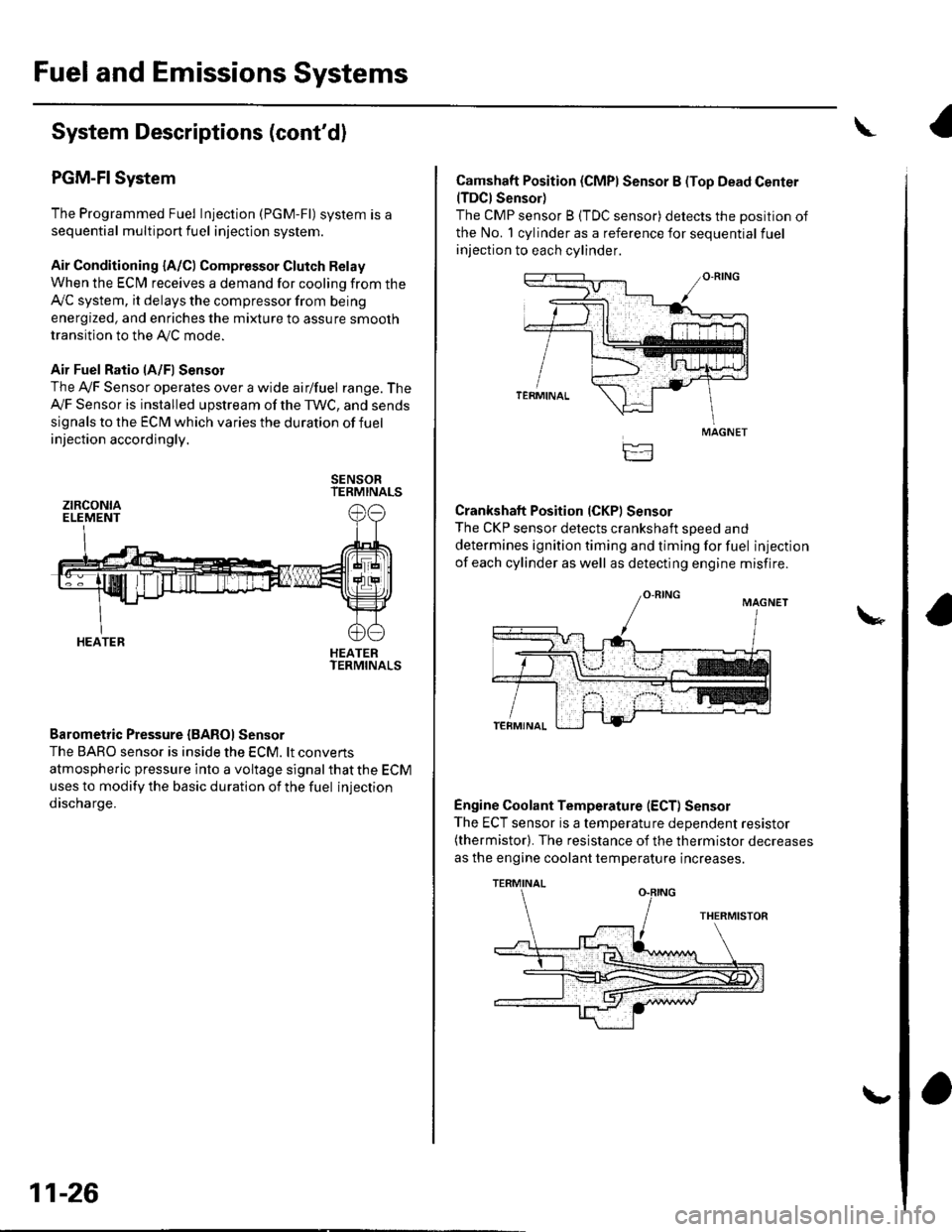
The Programmed Fuel Injection (PGM-Fl) system is a
sequential multiport fuel injection system.
Air Conditioning {A/C) Compressor Glutch Relay
When the ECfM receives a demand for cooling from the
Ay'C system, it delays the compressor from being
energized, and enriches the mixture to assure smooth
transition to the AVC mode.
Air Fuel Ratio lA/Fl Sensor
The Ay'F Sensor operates over a wide airlfuel range. The
Ay'F Sensor is installed upstream of the TWC, and sends
signals to the ECM which varies the duration of fuel
injection accordingly.
SENSORTERMINALS
HEATERTERMINALS
Barometric Pressure {BAROI Sensor
The BARO sensor is inside the ECM. lt convens
atmospheric pressure into a voltage signal that the ECM
uses to modify the basic duration of the fuel injection
discharge.
ztRcoNtaELEMENT
HEATER
11-26
\,
Camshaft Position (CMPI Sensor B (Top Dead Center(TDCI Sensor)
The CMP sensor B (TDC sensor) detects the position of
the No. 1 cylinder as a reference for sequential fuel
injection to each cylinder.
Crankshaft Position (CKPI Sensor
The CKP sensor detects crankshaft soeed and
determines ignition timing and timing for fuel injection
of each cylinder as well as detecting engine misfire.
Engine Coolant Temperature (ECT) Sensor
The ECT sensor is a temperature dependent resistor(thermistor). The resistance of the thermistor decreases
as the engine coolant temperature increases.
MAGNET
TERMINAL
Page 235 of 1139

Fuel and Emissions Systems
(
(
(
System Descriptions (cont'dl
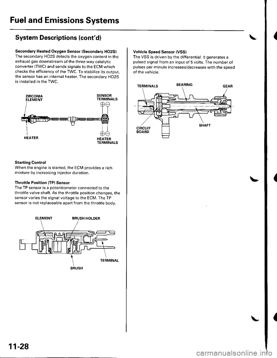
Secondary Heated Oxygen Sensor (Secondary HO2S)
The secondary HO2S detects the oxygen content in the
exhaust gas downstream of the three way catalytic
converter (TWC) and sends signals to the ECM which
checks the efficiency of the TWC. To stabilize its output,
the sensor has an internal heater. The secondarv HO2S
is installed in the TWC.
ztRcoNtaELEMENTSENSORTERMINALS
HEATERTERMINALS
Starting Control
When the engine is started, the ECM provides a rich
mixture by increasing injector duration.
Throttle Position ITP) Sensor
The TP sensor is a potentiometer connected to the
throttle valve shaft. As the throttle position changes, the
sensor varies the signal voltage to the ECM. The TP
sensor is not replaceable apart from the throftle body.
ELEMENTBRUSH HOLDER
gRUSH
11-28
Vehicle Speed Sensor (VSS)
The VSS is driven by the differential. lt generates apulsed signal from an input of 5 volts. The number ofpulses per minute increases/decreases with the speed
of the vehicle.
BEARING
Page 252 of 1139

""rr"a* JIr''lHr/cnN 1
CONNECTOR E
CONNECTOi K
CONNECTOFJ/GRN
IGNITIONSWITCH
lG2
'I
TESTTACHOMETERCONNECTO8
UNDER.HOOD
UNDER.DASHFUSE/RELAY BOX:
UNDER.DASHFUSE/FELAY BOX
Brake pedal pressed: closedBrake pedal releasedr open
POStTtON SWTTCH
,or"-9J3{51re* _{F "_.rl
4 ACG (1oAt1 tGN CO|L t15A)2 A/F HEATER {2OA)17 FUEL PUMP I15A}1O METER {7.5AI14 A/C CLUTCH RELAY {1OA}
11-45
Page 254 of 1139

Evaporative Emissions (EVAP) Control
System Monitor and Readiness code
NOTE:
All readiness code are cleared when the batterV is
disconnected or when the ECM is cleared with the
OBD ll scan tool or Honda PGM Tester.
The enable criteria must be repeated if the intake air
temperature (lAT) drops lower than 36'F (20"C) from
its value at engine $an up.
Enable Criteria
At engine start up, ECT and IAT are higher than 32'F(0"C) , but lower than 95'F (35"C).
At engine start up, the ECT and IAT are within 12'F(7'C) of each other.
Procedure
1. Connect the scan tool to the vehicle's data link
connector (DLC), and bring up the tool's generic
OBD ll mode.
2. Start the engine.
3. Test-drive the vehicle under stop-and-go conditions
with short periods of steady cruise. After about
2.5 miles (1.6 km), the readiness code should
switch f rom incomplete to complete.
4. lf the readinesscode isstill setto incomplete, check
for a temporary DTC. lf there is no DTC, one or
more of the enable criteria were probably not met;
repeat the procedure.
Air Fuel Ratio (A/Fl Sensor Monitor and
Readiness Code
NOTE:. Do not turn the ignition switch off during the
orocedure.. All readiness codes are cleared when the baftery is
disconnected or when the ECM is cleared with the
OBD ll scan tool or Honda PGM Tester.
Enable Criteria
ECT at 140'F (60"C) or higher.
Procedure
1. Connect the scan toolto the vehicle's data link
connector (DLC), and bring up the tool's generic
OBD ll mode.
2. Start the engine.
3. Test-drive the vehicle under stop-and-go conditions
with short periods of steady cruise. During the
drive, decelerate (wirh the throttle fully closed) for
5 seconds. After about 3.5 miles (2.2 km). the
readiness code should switch from incomDlete to
complete.
4. lfthereadinesscodeisstill set to incomplete, check
for a temporary DTC. lfthere is no DTC, the enable
criteria was probably not meU repeat the procedure.
Air/Fuel Ratio (A/Fl Sensor Heater Monitor
Readiness Code
NOTE; All readiness codes are cleared when the battery
is disconnected or when the ECM is cleared with the
OBD ll scan tool or Honda PGM Tester,
Procedure'1. Connect the scan tool to the vehicle's data link
connector {DLC), and bring up the tool's generic
OBD ll mode.
2. Start the engine, and let it idle for 1 minute. The
readiness code should switch from incomplete to
comDlete.
3. lf the readiness code is still set to incomplete, check
for a temporary DTC. lf there is no DTC, repeat theproceoure.
(cont'd)
11-47
Page 275 of 1139

PGM-FISystem
3.
DTC Troubleshooting (cont'dl
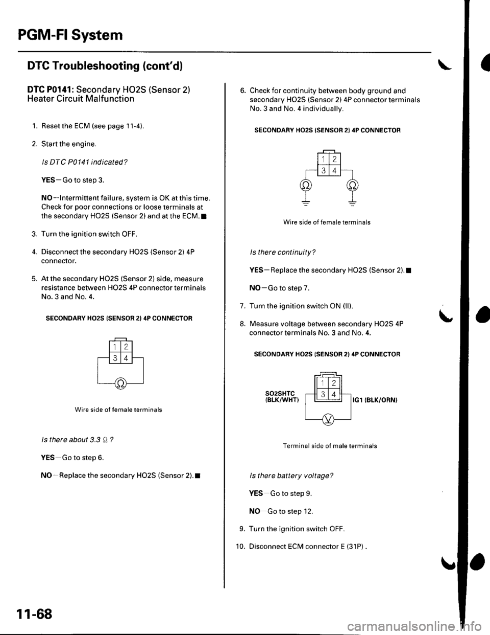
DTC P0141: Secondary HO2S (Sensor 2l
Heater Circuit Malfunction
1. Reset the ECM (see page 1 l-4)
2. Start the engine.
ls DTC P0141 indicated?
YES-Go to step 3.
NO-lntermittent failure, system is OK at this time.
Check for poor connections or loose terminals at
the secondary HO2S (Sensor 2) and at the ECM.I
Turn the ignition switch OFF.
Disconnect the secondary H02S (Sensor 2) 4P
connecror.
At the secondary HO2S (Sensor 2) side, measure
resistance between H02S 4P connector terminals
No.3 and No. 4.
SECONDARY HO2S (SENSOR 21 4P CONNECTOR
Wire side ol lemale terminals
ls there about 3.3 Q ?
YES Go to step 6.
NO- Replace the secondary HO2S (Sensor 2). t
5.
11-68
6. Check for continuity between body ground and
secondary H02S (Sensor 2) 4P connector terminals
No.3 and No. 4 individually.
SECONDARY HO2S {SENSOR 21 4P CONNECTOR
Wire side of female terminals
ls there continuity?
YES- Replace the secondary HO2S (Sensor 2).1
NO-Go to step 7.
Turn the ignition switch ON (ll).
Measure voltage between secondary H02S 4P
connector terminals No. 3 and No. 4,
SECONDARY HO2S (SENSOR 2l ilP CONNECTOR
t
7.
8.
9.
10.
s02sHTc{BLK/WHTIIG1 (BLK/ORN}
Terminal side of male terminals
ls there battery voltage?
YES Go to step 9.
NO Go to step 12.
Turn the ignition switch OFF.
Disconnect ECM connector E {31P)
Page 277 of 1139

PGM-FI System
DTC Troubleshooting (cont'dl
DTC P0171: Fuel System Too Lean
DTC P0172: Fuel System Too Rich
NOTE: lf some of the DTCS listed below are stored at
the same time as DfC PO17'l and/ot PO172,
troubleshoot those DTCS first, then recheck for P0171
andlot P0112.
P0107, P0108. P1 128. P1 129: Manifold absolute
pressure (MAP) sensor
P1 162. P1 166, P 1 167: 4,,/F sensor (Sensor 1 ) heater
P0137, P0138: Secondary HO2S (Sensor 2)
P014'l: Secondary HO2S (Sensor 2) heater
P1259: VTEC system
1. Check the fuel pressure (see page 11-'145).
ls luel pressure OK?
YES Go to step 2.
NO Check these items:
. lf the pressure is too high, replace the fuel
pressure regulator (see page 11-152).1. lf the pressure istoo low.checkthefuel pump,
the fuel feed pipe, the fuel filter, and replace the
fuel pressure regulator (see page 11-152).I
2. Start the engine. Hold the engine at 3,000 rpm with
no load (in neutral) until the radiator fan comes on.
11-70
3. Turn the ignition switch OFF.
4. With a vacuum pump, apply vacuum to the
evaporative emission (EVAP) canister purge valve
(A) from the evaporative emission (EVAP) canister
side.
' A973AX-041-XXXXX
Does it hold vacuum?
YES-Check the engine valve clearances and adjust
if necessary, lf the valve clearances are OK, replace
the injectors (see page 1 1-1 1 1).1
NO-Replace the EVAP canister purge valve.l
Page 296 of 1139

DTC Pl166: Ay'F Sensor (Sensor 1) Heater
Circuit Malfunction
1. Resetthe ECM (see page 11-4).
2. Start the engine.
ls DTC P1166 indicated?
YES-Go to step 3.
NO-lntermittent failure, system is OK at this lime.
Check for poor connections or loose terminals at
the Ay'F sensor relay, the A,/F sensor (Sensor 1), and
the EcM. !
3. Check the following fuse:
. No. 14 OPTION (30A)fuse in under-hood fuse/
reray Dox.. No. 2*B LAF (Ay'F) HEATER (20A) fuse in under-
dash fuse/relay box.. No. 4 ACG (10A) in underdash fuse/relay box.
Are any of the fuses blown?
YES Repair short in the wire between the Ay'F
sensor relay and the fuses.I
NO Go to step 4.
4. Measure voltage between ECM connector
terminals A1 and A24. 30 seconds after the ignition
switch is turned ON (ll).
ECM CONNECTOR A I31P)
Wire srde of lemale terminals
Is therc battery voltage?
YES-Update the ECM if it does not have the latest
soflware, or substitute a known-good ECM. then
recheck (see page 1 1-6). lf the symptom/indication
goes away with a known-good ECM, replace the
original ECM.I
NO-Go to step 5.
5. Measure voltage between ECM connector
terminals A22 and A24.
ECM CONNECTOR A {31P}
Wire side of female terminals
ls there battery voltage?
YES Go to step 6.
NO-Go to step 10.
6. Turn the ignition switch OFF.
7. Disconnect ECM connector E (31P).
8. Turn the ignition switch ON {ll).
(cont'd)
11-89