2002 HONDA CIVIC Tacho
[x] Cancel search: TachoPage 40 of 1139

Starter Circuit Troubleshooting
NOTE:. Airtemperature must be between 59'and 100'F (15'
and 38'C) during this procedure.
. After this test, or any subsequent repair, reset the
engine controle module (ECM) to clear any diagnostlc
trouble codes (DTCS) {see page 11-4).. The battery must be in good condition and fully
charged.. lf you disconnect the baftery, do the ECM idle learn
procedure (see page 11-139).
Recommended Procedure:. Use a starter system tester.. Connect and operate the equipment in accordance
with the manuf acturer's instructions.
Alternate Procedure
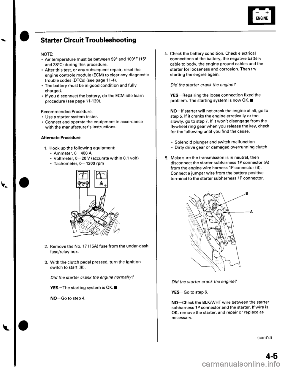
1. Hook up the following equipment:. Ammeter, 0 400 A. Voltmeter, 0 20 V (accurate within 0.1 volt). Tachometer,0 1200 rpm
2.Remove the No. 17 (15A) fuse from the under-dash
fuse/relay box.
With the clutch pedal pressed, turn the ignition
switch to start (lll).
Did the starter crank the engine normally?
YES-The starting system is OK.I
NO-Go to step 4.
3.
L
4-5
4. Check the battery condition. Check electrical
connections at the battery, the negative baftery
cable to body, the engine ground cables and the
starter for looseness and corrosion. Then try
starting the engine again.
Did the statter crank the engine?
YES Repairing the loose connection fixed the
problem. The starting system is now OK.!
NO lf starterwill notcranktheengine atall, goto
step 5. lf it cranks the engine erratically or too
slowly, go to step 7. lf it won't disengage from the
flywheel ring gear when you release the key, check
for the following until you find the cause.
. Solenoid plunger and switch malfunction. Dirty drive gear or damaged overrunning clutch
5. Make sure the transmission is in neutral, then
disconnect the starter subharness 1P connector (A)
from the engine wire harness 'lP connector (B).
Connect a jumper wire from the battery positive
terminal to the starter subharness 'l P connector.
Did the starter crank the engine?
YES-Go to step 6.
NO Check the BLK,ANHT wire between the starter
subharness 1P connector and the starter. lf wire is
OK, remove the starter, and repair or replace as
necessary.
(cont'd)
Page 73 of 1139

Cruise Control
Symptom Troubleshooting Index
NOTE:' The numbers in the table showthetroubleshooting sequence.. Before troubleshooting.- check the No, 10 (7.5A) and No. 4 (10A) fuses in the under-dash fuse/relay box. and the No. 7 (15A) fuse in theunder-hood fuse/relay box,- check that the horn sounds.- check the tachometer to see if it works properly.- check the speedometer lo see if it works properly.
SymptomDiagnostic procedureAlso check forCruise control cannot be
set
1. Check main switch (see page 4-42)
2. Check SET/RESUME/CANCEL switch (see page 4-42)
3. Test brake pedal position switch (see page 22-84) and checkits adjustment {see page 19,6)
4. Test clutch pedal position switch (see page 4-45) and check
its adjustment (see page 12-41
5. Check cruise control unit {see page 4-40}
6. Check vehicle speed sensor (VSS) (see page 22-65)
. Poor ground:
G501. Open circuit,
loose or
disconnected
term inals:
LT GRN,
BLI(ORN.
GRY/RED, BLU.
LT BLU,
BLUAA/HTCruise control can be set
but indicator light does
not go on
1. Check cruise control indicator bulb in gauge assembly {seepage 22-631
2. Check cruise control unit (see page 4-40)
. Poor ground:
G501. Open circuit,
loose or
disconnected
termrnats:
YEL, BLUA/ELar, 'i.a c^aa.l ic
noticeably higher or
lower than what was set
1. Check vehicle speed sensor (VSS) {see page 22-65)
Check cruise control actuator {see page 4-43)
2. Check cruise control unit (see page 4-40)
Excessive overshooting
or undershooting when
trying to set speed
1. Check cruise control actuator (see page 4-43)
2. Check vehicle speed sensor (VSS) (see page 22-65)
Check cruise control unit (see page 4-40)
3.
Speed fluctuation on a
flat road with cruise
control set
1. Check vehicle speed sensor (VSS) (see page 22-65)
Check cruise control actuator (see page 4-43)
2. Check cruise control unit (see page 4-40)
Vehicle does not
decelerate or accelerate
accordingly when SET/
RESUME/CANCEL button
is pushed
1. Check SET/RESU ME/CANCEL switch (see page 4-42)2. Check cruise control unit {see page 4-40)
Open circuit, loose
or disconnected
terminals:
GRY/RED,
LT GRN/BLKSet speed does not
cancel (engine rpm stays
high) when clutch pedal
is pushed
1. Testclutch pedal position switch (see page 4-45) and checkits adjustment (see page 12-4)
2. Check cruise control unit (see page 4-40)
Short to ground in
the LT BLU wire
Set speed does not
cancel when brake pedal
is pushed
'1. Test brake pedal position switch (see page 22-84) and checkits adjustment (see page 19-6)
2. Check cruise control unit (see page 4-40)
Open circuit, loose
or disconnected
terminals:
WHT/BLK
4-38
g,
Page 170 of 1139

Engine Lubrication
Oil Pressure Switch Test
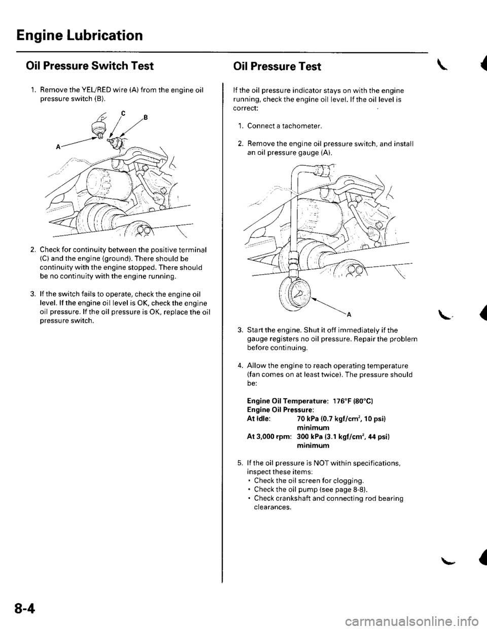
1. Remove the YEURED wire (A)from the engine oilpressure switch (B).
Check for continuity between the positive terminal(C) and the engine (ground). There should be
continuity with the engine stopped. There should
be no continuity with the engine running.
lf the switch fails to operate, check the engine oil
level. lf the engine oil level is OK. check the engine
oil pressure. lf the oil pressure is OK, replace lhe oil
Dressure switch.
2.
8-4
Oil Pressure Test
lf the oil pressure indicator stays on with the engine
running. check the engine oil level. lf the oil level is
correct:
Connect a tachometer.
Remove the engine oil pressure switch, and install
an oil pressure gauge {A).
{
'1.
\.(
4.
Sta rt the engine. Shut it off immediately if thegauge registers no oil pressure. Repair lhe problem
before continuing.
Allow the engine to reach operating temperature(fan comes on at least twice), The pressure should
be:
Engine Oil Temperature: 176'F (80'Cl
Engine Oil Pressure:
At ldle:70 kPa (0.7 kgf/cm', 10 psi)
mtntmum
At 3,000 rpm: 300 kPa (3.1 kgf/cm',44 psi)
minimum
lf the oil pressure is NOT within specifications,
inspect these items:. Check the oil screenforclogging.. Check the oil pump (see page 8-8).. Check crankshaft and connecting rod bearing
clearances.
I
Page 220 of 1139

ECM Data
You can retrieve data from the ECI\4 by connecting the OBD ll scan tool or the Honda PGM Tester to the data link
connector (DLC). The items listed in the table below conform to SAE recommended practice. The Honda PGM Tester
also reads data beyond that recommended by SAE to help you find the causes of intermittent problems.
The "operating values" listed are approximate and may vary depending on the environment and the individual
vehicle.
Unless noted otherwise, "at idle speed" means idling with the engine completely warmed up in the neutral position,
and the A,/C and all
Diagnostic
Trouble Code(DTC}
lf the ECM delects a problem, it will store it as a code
consisting of one letter and four numbers. Depending on
the problem, an SAE-defined code (Poxxx) or a Honda,
defined code {P1xxx) will be output to the tester.
The ECI\4 computes engine speed from the signals sent
from the crankshaft position (CKP) sensor. This data is
used for determining the time and amount of injected fuel.
detected, there is no
ourpul.
lf no problem is YES
Nearly the same as
tachometer indication
At idle speed;
The ECM converts pulse signals from the vehicle speed
sensor (VSS).Nearly the same as
speedometer
indication
Manifold
Absolute
Pressure(MAP)
The absolute pressure caused in the intake manifold by
engine load and speed.
With engine stopped: YES
Nearly the same as
almospnenc pressure.
At idle speed: about
20 4'1 kPa(150 310 mmHg,
6- 12 in.Hq).0.7 1.3 V
The ECT sensor converts coolant temperature into voltage
and signals the ECM. The sensor is a thermistor whose
internal resistance changes with coolant tempetature. The
ECM uses the voltage signals from the ECT sensor to
determine the amount of injected fuel.
With cold engine:
Same as ambient
temperature and IAT
With engine warmed
up; about 116 2'12"F
100'c).0.5-0.8 v
Air Fuel Ratio The A,/F sensor detects the oxygen content in the exha ust 0.0 - 1 .25 V(Ay'F) Sensor. gas and sends voltage signals to the Eclvl, Basedonthese 8.0 11.0mA(PGM(Sensor 1) signals, the ECM controls the airlfuel ratio. When the I Tester)
oxygen content is high (that is, when the ratio is leaner At idle speed:
than the stoichiometric ratio), the voltage signal is Iower. about 0.1 0.9 V
When the oxygen content is low (that is, when the ralio is
richer than the stoichiometric ratio). the voltage signal is
higher. The A'lF sensor signals are electrical current that
are indicated as voltaqe on the
The HO2S detects the oxygen content in the exhaust gas
and sends voltage signals to the ECM. Based on these
signals, the ECM controls the airlfuel ratio. When the
oxygen content is high (that is, when the ratio is leaner
than the stoichiometric ratio), the voltage signal is lower.
When the oxygen content is low (that is, when the ratio is
richer than the stoichiometric ratio), the voltage signal is
Secondary
Heated
Oxygen
Sensor(Secondary
H02S,
Sensor2)
0.0 1.25 V NO
At idle speed:
about 0.1 0.9 V
(cont'd)
11-13
Page 252 of 1139

""rr"a* JIr''lHr/cnN 1
CONNECTOR E
CONNECTOi K
CONNECTOFJ/GRN
IGNITIONSWITCH
lG2
'I
TESTTACHOMETERCONNECTO8
UNDER.HOOD
UNDER.DASHFUSE/RELAY BOX:
UNDER.DASHFUSE/FELAY BOX
Brake pedal pressed: closedBrake pedal releasedr open
POStTtON SWTTCH
,or"-9J3{51re* _{F "_.rl
4 ACG (1oAt1 tGN CO|L t15A)2 A/F HEATER {2OA)17 FUEL PUMP I15A}1O METER {7.5AI14 A/C CLUTCH RELAY {1OA}
11-45
Page 332 of 1139

18.Remove the VTEC oil pressure switch (A) and
installthe specialtools as shown, then reinstall the
VTEC oil pressure switch.
07406-0070300
\lsl
t:={
R
07406-0020201 ot07MAJ-PY,lo11A and07MAJ-PY40120
A22 N.ml2.2kgt.m,16 rbf.ft)
19.
20.
21.
22.
07NAJ-P07010A
Reconnect the VTEC solenoid valve 2P connector
and VTEC oil pressure switch 2P connector.
Connect a tachometer or OBD ll scan tool/Honda
PGM Tester to the DLC.
Start the engine. Hold the engine at 3,000 rpm with
no load (in neutral) until the radiator fan comes on.
Checkthe oil pressure at engine speeds of 1,000
and 2.000 rpm. Keep the measuring time as shon
as possible {less than 1 minute) because the engine
is running with no load.
ls the oil ptessure below 49 kPa (0.5 kgf/cnf,
7 psi)?
YES Go to step 23.
NO Inspect the VTEC solenoid valve (see page 11-'t28l.a
23.
24.
25.
26.
Turn the ignition switch OFF.
Disconnect the VTEC solenoid valve 2P connector.
Aftach the battery positive terminalto VTEC
solenoid valve 2P connector terminal No. 2.
Start the engine, then connect the battery negative
terminalto VTEC solenoid valve 2P connector
terminal No. 1, and check the oil pressure at an
engine speed of 3,000 rpm.
ls the oil pressure above 390 kPa (4.0 kgt/crtf ,
57 psi)?
YES Go to step 27.
NO Inspectthe VTEC solenoid valve (see page I1-
12Al.a
27. With the battery terminals still connectedtothe
VTEC solenoid valve connector, measure voltage
between ECM connector terminal 89 and bodv
oround.
ECM CONNECTOR B {24P)
ls there battery voltage above 4,000 tpm?
YES Go to step 28.
NO-Replace the VTEC oil pressure switch (see
page 11'128).1
Turn the ignition switch OFF.
Disconnect the battery terminals from the VTEC
solenoid valve terminal connector.
(cont'd)
28.
29.
Wire side of female terminals
11-125
Page 345 of 1139

ldle Control System
ldle Speed lnspection
NOTE:' Leave the idle air control (lAC) valve connecled.. Before checking the idle speed, check these items:- The malfunction indicator lamp (MlL) has not been
reported on.- lgnition timing- Spark plugs- Air cleaner- PCV system. Pullthe parking brake lever up. Start the engine, and
make sure the headlights are off.
1. Disconnect the evaporative emission (EVAP)
canister purge valve 2P connector.
2. Connect a tachometer (A)to the test tachometer
connector (B), or connect the Honda PGM Tester (C)
or an OBD ll scan tool to the data link connector(DLC) (D) located under the driver's side of the
dashboard.
11-138
4.
3.
5.
6.
Start the engine. Hold the engine at 3,000 rpm with
no load (in neutral) until the radiator fan comes on,
then let it idle.
Check the idle speed with no-load conditions;
headlights, blower fan, radiator fan, and air
conditioner off.
ldle speed should be: 750 t 50 rpm
Let the engine idle for 1 minute with the heater fan
switch on Hl and air conditioner on, then check the
idle speed.
ldle speed should be: 750 t 50 rpm
NOTE: lf the idle speed is not wilhin specification,
go to the Symptom Troubleshooting Index,
Reconnect the EVAP canister purge valve 2P
connector.
Page 524 of 1139

DTC 22: Vehicle Speed Sensor Signal
DTC 23: Engine Speed Signal
NOTE:. lf the MIL indicator is ON, troubleshoot the PGIVI-Fl
system first.. Even though the system is operating normally, the
EPS indicator will come on under the following
conditions.
- Condition 1:. The vehicle was traveling at least '12.4 mph(20 km/h), then. A rapld change in vehicle speed was detected,
then. The vehicle (or the vehicle speed sensor signal)
stopped for at least 5 seconds, and. The engine speed was still 1,640 rpm or higher for
at least 5 seconds- Condition 2:
After the vehicle (or the vehicle speed sensor
signal) has stopped for at least 10 seconds, yetthe
engine speed was still 1,640 rpm or higher for at
least 20 seconds.- Condition 3:
When the vehicle speed is 10 km/h (6.2 mph) or
above and the engine is running at 280 rpm or
below for 3 seconds.
1. Start the engine and check the tachometer.
ls the tachometer working correctly?
YES- Go to step 2.
NO-Go to step 9.
2. Test-drive the vehicle above 15 km/h {9.3 mph).
ls the speedometer working correctly?
YES Go to step 3.
NO-Perform the speedometer system
troubleshooting {see page 22-651.a
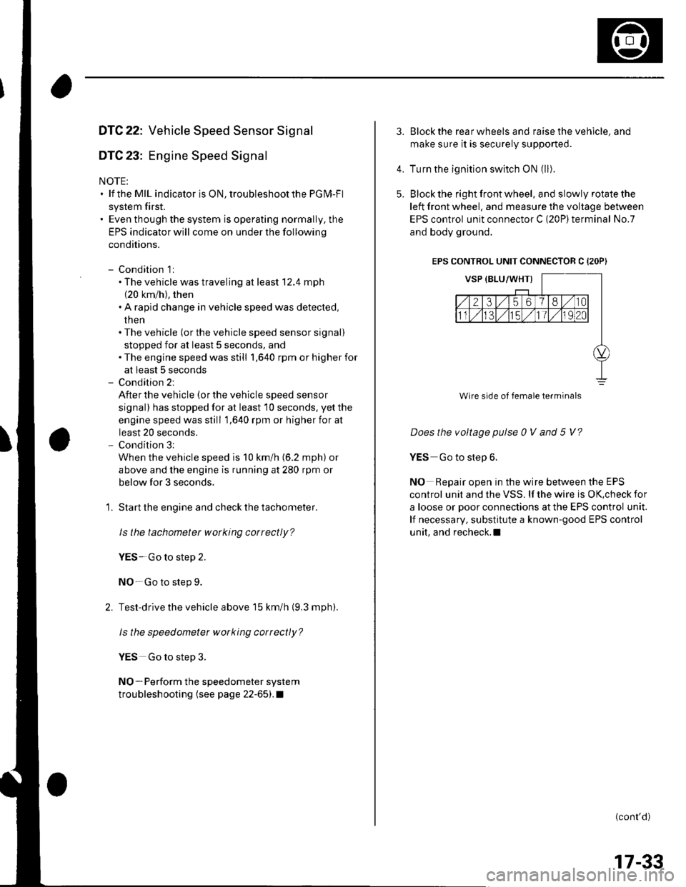
3.Block the rear wheels and raise the vehicle, and
make sure it is securely supported.
Turn the ignition switch ON (ll).
Block the right front wheel, and slowly rotate the
left front wheel, and measure the voltage between
EPS control unit connector C (20P)terminal No.7
and body ground.
EPS CONTROL UNIT CONNECTOR C {2OP)
Does the voltage pulse 0 V and 5 V?
YES Go to step 6.
NO Repair open in the wire between the EPS
control unit and the VSS. lf the wire is OK,check for
a loose or poor connections at the EPS control unit.
lf necessary, substitute a known-good EPS control
unit, and recheck.l
(conr'd)
4.
5.
Wire side of female terminals
17-33