2002 HONDA CIVIC seat adjustment
[x] Cancel search: seat adjustmentPage 96 of 1139

\
Engine Mechanical
Cylinder Head
Special Tools
Comoonent Location Index
Engine Compression Inspection
VTEC Rocker Arm Test ........... ............ 6-7
VTC Actuator Inspection .................... 6-8
Valve Clearance Adjustment ............. 6-9
Crankshaft Pulley Removal and Installation .............. 6-11
Cam Chain Removal ........................... 6-12
Cam Chain Installation ....................... 6-15
Auto-Tensioner Removal/1nsta11ation ......................... 6-19
Chain Case Oil Seal Installation ........ 6-21
Cyf inder Head Cover Removal .......... 6-22
Cylinder Head Removal ..................... 6-23
WC Actuator. Exhaust Camshaft Sorocket
Repf acement .........6-24
Cylinder Head Inspection for Warpage ...................... 6-25
Rocker Arm Assembly Removal ................................. 6-26
Rocker Arms and Shafts
Disassembly/Reassembly .............. 6-27
Rocker Arms and Shafts Inspection ............................ 6-28
Camshaft Inspection .......................... 6-29
Valves, Springs, and Valve Seals Removal ................ 6-31
Valve Insoection ...................... ........... 6-32
Valve Stem-to-Guide Clearance Insoection ............... 6-32
Valve Guide Reolacement ................. 6-33
Valve Seat Reconditioning ................ 6-35
Valves, Springs, and Valve Seals Installation ............ 6-37
Rocker Arm Assemblv Installation .... 6-38
Cvlinder Head Installation ........................................... 6-39
Cylinder Head Cover Installation ...... 6-41
6-2
6-3
b-t'
Page 505 of 1139

Rack Guide Adjustment
Special Tool Required
Locknut wrench, 43 mm 07MAA-S100200
1. Set the wheels in the straight ahead position.
2. Remove the heat shield (A).
3.
9.8 N.m (r.0 kgf.m,7.2lbtft)
Remove the transmission mount bracket (see step
32 on page 13-8).
Loosen the rack guide screw locknut (A)with the
special tool, then remove the rack guide screw (B).
Remove the old sealant from rack guide screw, and
apply new sealant to the middle of the threads (A).
Loosely installthe rack guide screw on the steering
gearDox.
'-.i. '' '
07MAA-S100200
6. Tighten the rack guide screw (A)ro 25 N.m (2.5
kgf.m, 18lbf.ft). then loosen it.
5" Max.
j i-rrrr-,
I 4il N.m{a.5 kgf.m,33lbt.ft)
Retighten the rack guide screw to 6 N.m (0.6 kgf m,
4 lbf.ft), then back it off to the specified angle.
Specified Return Angle: 5' Max.
Hold the rack guide screw stationary with a wrench,
and tighten the locknut by hand until it's fully
seated.
Installthe special tool on the locknut (B), and hold
the rack guide screw (A) stationary with a wrench,
Tighten the locknut an additional 30" with the
specialtool.
Reinstall the transmission mount bracket and heat
sh ie ld,
Check for unusual steering effort through the
complete turning travel.
Check the steering wheel rotation play (see page
17-4) and the power assist (see page 17-4).
11.
7.
9.
10.
12.
17-13
Page 654 of 1139

Body
DoorsComponent Location Index ...........Door Panel Removal/lnstallation .....,..........Door Outer Handle ReplacementDoor Latch ReplacementDoor Glass and RegulatorReplacementDoor Sash Trim Replacement .......................
Door Glass Outer WeatherstripReplacement
Door Weatherstrip Beplacement
Door Glass Adjustment .................................Door Position Adjustment .............................Door Striker Adiustment ................................MirrorsComponent Location Index ...........................Power Mirror Replacement ...........................Mirror Holder Replacement ...........................Rearview Mirror Rep1acement ......................
GlassComponent Location Index ...........................Windshield Replacement
Bear Window Rep1acement ...........................
Ouarter Glass Replacement ..........................MoonroofComponent Location Index ...........................Symptom Troubleshooting Index
Glass Height Adjustment ...............................
Glass ReplacementWind Def lector 8ep1acement ........................Drain Channel Rep1acement ..........................Sunshade Replacement .................................Motor ReplacementFrame and Drain Tube Replacement ............Drain Channel Slider and Cable AssemblyReplacementLimit Switch Adjustment ...............................Closino Force and ODenina Draq Check ......lnterioi TrimComponent Location Index ...........................Trim Removal/lnstallation DoorArea ..........Trim Removal/lnstallation-Rear Side AreaTrim Removal/lnstallation-Cargo Floor AreaTrim Removal/lnstallation-Hatch Area .........Headliner Removal/lnstallation* Carpet Rep1acement .......................................ConsolesConsoles, Front and RearRemova l/lnsta llationFront Console Disassembly/Reassembly .....
20-220,420-620-7
20-920 t0
20- 10
20-1120-1120-1220 13
20-1420-1520-1520-16
20 1120-1920-2520-29
20,3520-3620-3720-3120-3820 3920-4020-4120,42
20 4420-4620,44
20-4920 50
20-51
DashboardInstrument Panel Removal/lnstallation ........Driver's Dashboard Lower CoverRemovat InstallationDriver's Dashboard Under CoverRemova t Insta llation
Oriver's Pocket Removal/lnstallation ............Shift Lever Trim Removal/lnstallation ..........Center Panel Removal/lnstallation ...............Passenger's Dashboard Lower CoverRemova l/lnsta llat ionx Glove Box Removal/lnstallationDashboard Side VentRemoval/lnstallation .................................. 20-64Beverage Holder Removal/lnstallation ........ 20-64Driver'sTray Removal/lnstallation ............... 20-65Passenger's Tray Removal/lnstallation ........ 20 65* Dashboard Removal/lnstallation .................. 20-66Steerinq Hanqer Beam Reolacement ........... 20-68Seats "
Component Location Index ........................... 20-10* Front Seat Removal/lnstallation ................... 20-11* Front Seat Disassembly/Reassembly-Driver's .................................. 20-73* Front Seat Disassembly/Reassembly-Passenger's ........................... 20-74* Front Seat Cover Replacement ..................... 2O-75Rear Seat Removal/1nsta11ation ..................... 20-80Rear Seat-back Latch Replacement .............. 20-81Rear Seat-backStriker Replacement ............ 20-81
20-59
20-59
Rear Seat-back Cover Replacement ............. 20-82Rear Seat Cushion Cover Replacement ....... 20.84BumpersFront Bumper Removal/lnstallation .............Rear Bumoer Removal/lnstallation ...............HoodAdjustmentHood Seal ReplacementHood Insulator Rep1acement .........................Hatch
20-6020,6020 6120-62
20-63
20-63
20,8520-86
20-4720,8820,89
20-5220-5320-5420-55
20-5720-58
Adjustment ................... 20-90Hatch Suppon Strut Replacement ................ 20-91Hatch WeatherstriD Reo1acement ................. 20-92
Fuel Fill DoorAdiustment ................... 20-93Exterior TrimFront Grille Replacement ..............Cowl Covers Replac"rn""t .. . .....................A pillar Corner Trim Replacement ................Roof lMolding Replacement ...........................Rear License Trim ReplacementHatch Spoiler 8ep1acement ...........................Emblem Rep1acement .........................
20-9420-9520-9620-9720,9820-9920-100
Page 909 of 1139

Exterior Lights
Headlight Adjustment
Before adiusting the headlights:. Park the vehicle on a level surface.. Make sure the tire pressures are correct.. The driver or someone who weighs the same should
sit in the driver's seat.
'1. Clean the outer lens so that you can see the center
of the headlights (A).
Headlights become very hot during use; do not
touch them or any attaching hardware immediately
after they have been turned off.
22-78
7.5 m {25 ftl
\
2. Park the vehicle 7.5 m (25 ft) away from a wall or a
screen (A).
3. Open the hood.
Page 1134 of 1139

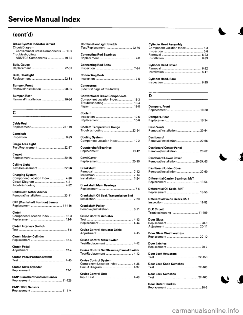
Service Manual Index
(cont'dl
Brake System Indicator CircuitCircuit DiagramConventional Brake Components..... 19-9TroubleshootingABS/TCS Components .... ....... ...... 19-55
Bulb, GeugeRep|acemenl................ .. ............2263
Bulb, HeadlightReplacement ......................................... 22-A1
Bumper, FrontRemoval/1nsra11ation ............................ 20 85
Bumper, RearRemoval/lnstallation... ... . .....20.86
Combination Light SwilchTesVReplacement ..............................22 80
Connecting Rod BearingsRep|acement...................... .......-....7-8
Connecting Rod Boltsf nspection ....................-.-.-.-.................... 7 -24
Connecting RodsInspection ........,,.,.,...,.,.,.,.,,,,.,,,.,.,.,.,.,.,.,.. 7 5
Connectors(See first page of this Index)
Conventional Brake Component3Component Location Index ................... 19'3Troub1eshootin9 ..................................... 19-4
Cylinder Head AssemblyComponent Location Index ..................... 6-3Inspection ................................................. 6 6Removal ..........&�23Insta11alion .............................................. 6 39
Cylinder Head Cover8emova1 ..............-.-................................. 6-22Installation ..............................................6-41
Cylinder Head, BareInspecton..,.....,.
D
c
Cable ReelReplacement....................................... 23-1 19
CamshaftInspection .......................-...-................... 6-29
Cargo Area LightTesVRep1acement ................................ 22-97
CarpetReplacement.....-...-..... ... ......-.20-55
Ceiling Light-estrReplacement ................................ 22.96
Charging SystemComponent Location Index................... 4-20Circuit Diagram ...................................... 4-21
19-8
CoolantInspection .................. ..... .. 106Replacement................. ... . .. 10 6
Coolant Temperature Gat|geTroub1eshootin9................................... 22 64
Cooling SyslemComponent Location Index................... 10-2
Countershaft BearingsReplacement............... ..................... 13-42
Cowl CoverReplacement............... .. ..... ....20-95
CrankshaftRemoval .................................................. 7 -12
Repair ..................
Inspec(on,,,,,........1 14
Dampers. FrontReplacement................ ..................... 18 20
Oampers, RearRep1acement......................................... 18-34
Dash VentsBemoval/lnstallation .-.......................... 20-64
DashboardBemoval/1nsta11ation ............................ 20-66
Oashboard Center PanelRemoval/1nstaf 1ation ............................ 20 62
Dashboard Lower CoverRemoval/lnstallation ...................... 20-59, 63
Dashboard Under CoverRemoval/lnstallation ............................ 20 60
Diff erential Carrier Bearings, M/TRep1acement,,......,...,...,.,.,,,.,.,,,........,.,. 13-54
Ditferential Oil Seals, M/T8ep1acement......................................... 13-55
Differential Pinion Gears, M/TInspection .,....-,.,,,.,..,.-,.,.........,.,.,,, 13 53
OLC CircuitTroubleshooting ................................ 1 1-109
Door GlassRep1acement.,.,,,,,,,,,,,.,,,,,,,,,,.,.,.,.,.,,,,,,.,, 20-9Adjustment. .. .....................20-11
Door Glass WeathelstripsReplacement .............-.. . . . ..........-......20 10
Door LatchesReplacement ..........-.-.............................. 20-7
Door Lock ActuatorsTest ...................................................... 22-154
Door Lock Knob SwitchesTest -......... . . . - . . . . . . . . ......22-160
Door Lock SwitchesTest ........... ............................ ............. 22-160
Door Outer HandlesRep1acemen1 ........................................... 20-6
3
Child Seat Tether AnchorRemoval/lnstaf lat;on .. ........................ 23 11
CKP (Crankshaft Position) SonsorReplacement....................................... 1 1-116
ClutchComponentLocation 1ndex................... 12-3Rep1acemen1........................................... 12-9
Clutch InteYlock SwitchTest.....-........-...-............. ...---.-.......4-6
Clutch Master CylinderReplacement........................................... 12 5
clutch PedalAdjustment ............................................. 12 4
Clutch Pedal Position SwitchTest.,.,,,,,.,,,.,.,,,,,,.,.,,,,,,,,,.,,,,,.. ......445
lnstallation.................. . ..... .....1-24
Crankshalt Main BearingsReplacement........-.-.................................. 7-6
CrankshaftOil Seal,Transmission End1nstanation .............................................. 7 28
Crankshafl PulleyRemoval/lnstallation -..................-.......... 6-1 1
Cruise Control Actuator
Troubleshooting
Clutch Slave CylindorBeplacemeit...
...................... 4-43
.......4-22
Test
12-1
RepIacement........................................... 4-44
Cruise Control Actuator CableAdjustment ............................................. 4 45
Cruise Control Main SwitchTesVRep1acement .................................. 4 42
Cruise Control Set/Resume/Cancel SwitchTesVRep1acement .................................. 4 42
Cruise Control SystomComponent Localion Inde\................... 4-36Circuit Diagram ....-................................. 4 37
Cruise Control UnitInputTest.............................. .. ...4,40CMP {Camshaft Positionl Senso]Replacement....-...-.............................. 1 1-128
CMP (TDC) SensorsReplacement............-.......................... 1 1 1 14
Page 1139 of 1139

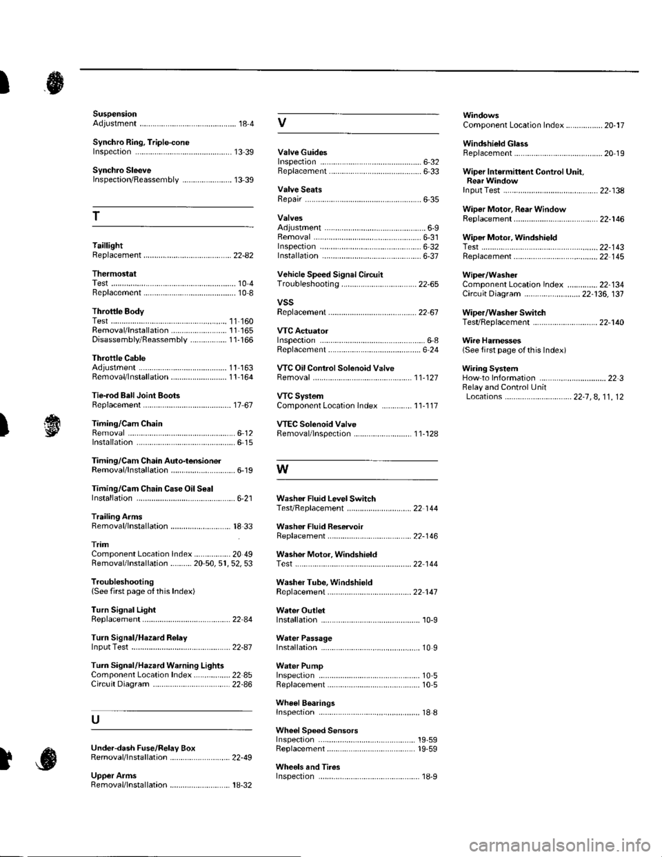
SuspensionAdjustment................-............................184 VComponent Location Index................. 20-17
Windshield GlessReplacement............-..............-............. 20 19
Synchro Ring, Triple-coneInspection...............-..........................1339 ValveGuides
Synchro SleeveInspectaon/Reassemb1y ....................... 13 39
Inspection ............-.-................................ 6 32Beplacement ..........-................................ 6 33 Wiper Intermittent Control Unit,Rear WindowInput Test
T
Valve SeatsRepair ...................................................... 6 35.....22-134
WiDer Motor, Rear WindowRep1acement....................................... 22-1 46Adjustment .-.-.......Removal ...-...-......................................-... 6-31 WiDer Motor, windshield6-9
.....6-32 Test.......-..........-.....-.............................22-143Taillight
ThermostaiTest ........................
Inspec!on
Vehicle Speed Signal Circuit
VTC System
Wiper/WasheI
Wi.ing System
10 4 Troubleshooting .....-... ..........................22-65 Component Location In dex ..............22-134Replacement.....-...-....... ...................... 10 IvssThrottle BodyTest ..................Removal/lnstallation .. . . . . . .. ... 11-'165 VTC ActuatorDisassembly/Feassemb|y................-11-166 Inspection
Circuit Diagram .......................... 22-136, 131
Replacement -.............. ............ .............22 61 Wiper/Washor SwitchTesVReplacement .............................. 22-1 40
.................68 WireHarnesses
11-160
Replacement ........................................... 6 24 (Seefirstpageofthislndex)Throttle CableAdjustment ...... ...-.................... 11163 VTC Oil ConlrolSolenoid ValveRemoval/1nsta11ation..........................11164 Removal....-...-... |1-127 HowtoIn{ormation ...............................223Belay and Control UnitLocations .-....-.............. -.-.-....- 22-7, 4, 1 1, 12Beplacement.........-............................... 1767 ComponentLocationlndex.............. 11-117Tie-rod Ball Joint Boots
lnstallation
Replacement
Turn Signal/Hazard Relay
tsTiming/Cam ChainVTEC Solenoid Valve...612 Femoval/lnspection....-......................11-128................ 6 15
Timing/Cam Chain Auto-tensionelRemoval/1nsta11ation..............................6-19 W
Troubleshooting{See first page ot this Index)
Turn Signal Light
Timing/Cam Chain CaseOil SealInstallation......................-......................6,21 Washer Fluid Level SwitchTesVReplacement .............................. 22 1 44Trailing ArmsRemoval/lnstallation .............. . . . . ..... 18 33 Washer Fluid ReservoirReplacement ....................................... 22-1 46tnmComponent Location lndex ................- 20 49 Washer Motor, WindshieldRemoval/lnstallation ..-.......20 50,51,52,53 Test -..............-.............. ........................22 144
Washer Tube, WindshieldReplacement......-...-............................ 22 1 47
W.ter Outlet.........22 A4 Installation ..................-........................... '10-9
InputTest........22-87 lnstallation................ 10IWeter Passage
Wheels andTires
Turn Signal/Hazard Warning Lights Water PumpComponent Location In dex .................22 85 Inspection ........................... .. . . . ....... 10 5Circu it Diagram ................-................... 22-86 Replacement .-......................................... 10 5
U
WheelBearingsInspec|ion ....................................... ....... 18 8
Wheel Speed SensorsInspection ..-..,.,.,,.,,,,,.,.,,,...................... 19-59Replac€ment ........-....... . . . . . . .. -.... 19-59UndeFdash Fuse/R€lay BoxRemoval/lnstaf lation ............................ 22-49
Upper ArmsRemoval/|nsta11ation................. ... 18-32
],sInspect|on