Page 3 of 216
Maintenance and Specifications 156
Hood 160
Engine compartment 161
Engine oil 164
Battery 167
Fuel information 175
Air filter(s) 190
Part numbers 195
Refill capacities 195
Lubricant specifications 196
Engine data 198
Vehicle dimensions 198
Accessories 202
Index 205
All rights reserved. Reproduction by any means, electronic or mechanical
including photocopying, recording or by any information storage and retrieval
system or translation in whole or part is not permitted without written
authorization from Ford Motor Company. Ford may change the contents without
notice and without incurring obligation.
Copyright 2001 Ford Motor Company
Table of Contents
3
Page 9 of 216
Vehicle Symbol Glossary
Child Safety Door
Lock/Unlock
Interior Luggage
Compartment Release
Symbol
Panic AlarmEngine Oil
Engine CoolantEngine Coolant
Temperature
Do Not Open When HotBattery
Avoid Smoking, Flames,
or SparksBattery Acid
Explosive GasFan Warning
Power Steering FluidMaintain Correct Fluid
LevelMAX
MIN
Emission SystemEngine Air Filter
Passenger Compartment
Air FilterJack
Check fuel capLow tire warning
Introduction
9
Page 12 of 216

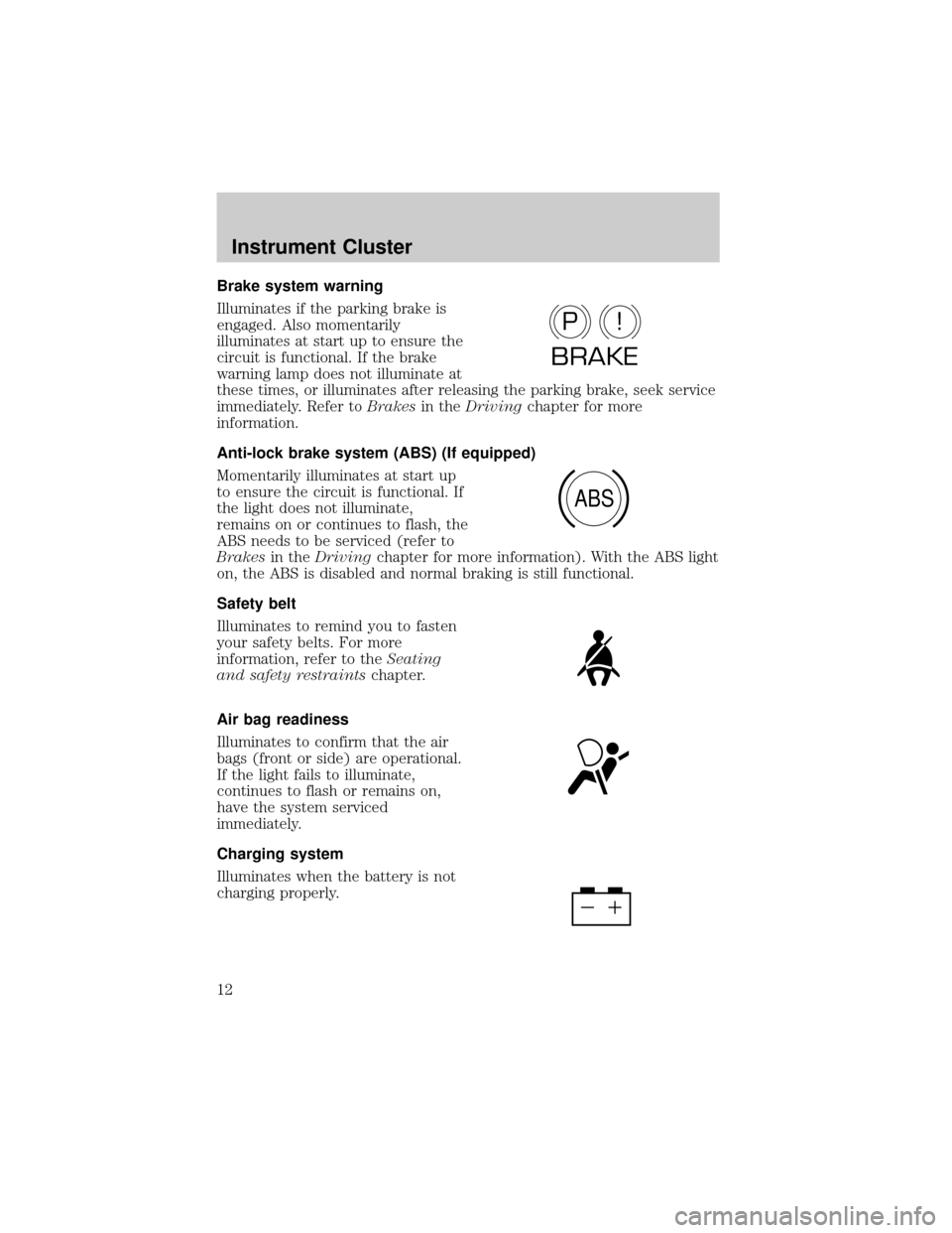
Brake system warning
Illuminates if the parking brake is
engaged. Also momentarily
illuminates at start up to ensure the
circuit is functional. If the brake
warning lamp does not illuminate at
these times, or illuminates after releasing the parking brake, seek service
immediately. Refer toBrakesin theDrivingchapter for more
information.
Anti-lock brake system (ABS) (If equipped)
Momentarily illuminates at start up
to ensure the circuit is functional. If
the light does not illuminate,
remains on or continues to flash, the
ABS needs to be serviced (refer to
Brakesin theDrivingchapter for more information). With the ABS light
on, the ABS is disabled and normal braking is still functional.
Safety belt
Illuminates to remind you to fasten
your safety belts. For more
information, refer to theSeating
and safety restraintschapter.
Air bag readiness
Illuminates to confirm that the air
bags (front or side) are operational.
If the light fails to illuminate,
continues to flash or remains on,
have the system serviced
immediately.
Charging system
Illuminates when the battery is not
charging properly.
P!
BRAKE
ABS
Instrument Cluster
12
Page 67 of 216
Sounding a panic alarm
Press this control to activate the
alarm.
To deactivate the alarm, press the
control again or turn the ignition to
ACC or ON.
Opening the trunk
Press the control once to open the
trunk.
Ensure that the trunk is closed and
latched before driving your vehicle.
Failure to latch the trunk
completely may cause objects to fall
out of the trunk or block the rear
view.
Replacing the battery
The remote transmitter is powered by one coin type three-volt lithium
battery CR2032 or equivalent. Typical operating range will allow you to
be up to 10 meters (33 feet) away from your vehicle. A decrease in
operating range can be caused by:
²weather conditions
²nearby radio towers
²structures around the vehicle
²other vehicles parked next to the vehicle
Locks and Security
67
Page 68 of 216
To replace the battery:
1. Twist a thin coin between the two
halves of the transmitter near the
key ring. DO NOT TAKE THE
FRONT PART OF THE
TRANSMITTER APART.
2. Place the positive (+) side of new
battery in the same orientation.
Refer to the diagram inside the
transmitter unit.
3. Snap the two halves back
together.
Replacement of the battery willnotcause the remote transmitter to
become deprogrammed from your vehicle. The remote transmitter should
operate normally after battery replacement.
Replacing lost transmitters
If a remote transmitter has been lost
and you would like to remove it
from the vehicle's memory, or you
would like to purchase additional
remote transmitters and have them
programmed to your vehicle:
²Takeallyour vehicle's
transmitters to your dealer for
programming, or
²Perform the programming
procedure yourself
Locks and Security
68
Page 125 of 216

Fuse/Relay
LocationFuse Amp
RatingPassenger Compartment Fuse
Panel Description
METER 10A Backup Lamps, Engine Controls,
Instrument Cluster, Rear Window
Defrost, Shift Lock, Warning
Chime, Turn Signal Switch
WIPER 20A Wiper/Washer, Blower Relay
STOP 15A Stop Lamps
TAIL 15A Exterior Lamps, Instrument
Illumination
SUN ROOF 15A Power Moonroof
ASC 10A Speed Control
CIGAR 20A Cigar Lighter
AIR BAG 10A Joint Connector, Air Bag
Diagnostic Monitor
FOG 10A Fog Lamps, Daytime Running
Lamps (DRL)
AUDIO 15A Radio
FUEL
INJECTOR10A HO2S, Evaporative Emission
Purge Flow Sensor
P. WINDOW 30A CB Power Windows
BLOWER 30A CB A/C-Heater
Power distribution box
The power distribution box is located in the engine compartment. The
power distribution box contains high-current fuses that protect your
vehicle's main electrical systems from overloads.
Always disconnect the battery before servicing high current
fuses.
Always replace the cover to the power distribution box before
reconnecting the battery or refilling fluid reservoirs
If the battery has been disconnected and reconnected, refer to the
Batterysection of theMaintenance and specificationschapter.
Roadside Emergencies
125
Page 132 of 216

JUMP STARTING YOUR VEHICLE
The gases around the battery can explode if exposed to flames,
sparks, or lit cigarettes. An explosion could result in injury or
vehicle damage.
Batteries contain sulfuric acid which can burn skin, eyes, and
clothing, if contacted.
Do not attempt to push-start your vehicle. Automatic
transmissions do not have push-start capability; also, the
catalytic conveter may become damaged.
Preparing your vehicle
When the battery is disconnected or a new battery is installed, the
transmission must relearn its adaptive strategy. As a result of this, the
transmission may shift firmly. This operation is considered normal and
will not affect function or durability of the transmission. Over time, the
adaptive learning process will fully update transmission operation to its
optimum shift feel.
1.Use only a 12±volt supply to start your vehicle.
2. Do not disconnect the battery of the disabled vehicle as this could
damage the vehicle's electrical system.
3. Park the booster vehicle close to the hood of the disabled vehicle
making sure the two vehiclesdo nottouch. Set the parking brake on
both vehicles and stay clear of the engine cooling fan and other moving
parts.
4. Check all battery terminals and remove any excessive corrosion before
you attach the battery cables. Ensure that vent caps are tight and level.
5. Turn the heater fan on in both vehicles to protect any electrical
surges. Turn all other accessories off.
Roadside Emergencies
132
Page 133 of 216
Connecting the jumper cables
1. Connect the positive (+) booster cable to the positive (+) terminal of
the discharged battery.
Note:In the illustrations,lightning boltsare used to designate the
assisting (boosting) battery.
2. Connect the other end of the positive (+) cable to the positive (+)
terminal of the assisting battery.
+–+–
+–+–
Roadside Emergencies
133