2002 DODGE RAM lock
[x] Cancel search: lockPage 218 of 2255

(9) Remove the bolts/nuts from the pedal assembly
and remove the assembly.
INSTALLATION
(1) Position the replacement pedal assembly on the
dash and cowl.
(2) Install the bolts/nuts and tighten to 28 N´m (21
ft. lbs.).
(3) Connect the front cable to the arm on the pedal
assembly.
(4) Tighten the front cable grommet to the floor-
pan and the cable retainer, roll the carpet back.
(5) Connect the wires to the brake lamp switch.
(6) Install the knee bolster, (Refer to 23 - BODY/
INSTRUMENT PANEL/STEERING COLUMN
OPENING COVER - INSTALLATION).
(7) Raise the vehicle.
(8) Adjust the parking brake cable tensioner.
CABLES
REMOVAL
REMOVAL - REAR PARK BRAKE CABLE
(1) Raise and support the vehicle.
(2) Lockout the parking brake cable (Fig. 53).
(3) Loosen cable adjuster nut.
(4) Remove the rear park brake cable from the
intermediate park brake cable.(5) Compress tabs on cable end fitting on the rear
park brake cable to the frame mount bracket. Then
pull the cable through the bracket.
(6) Disengage the park brake cable from behind
the rotor assembly. (Fig. 54).
(7) Compress cable tabs on each cable end fitting
at the brake cable support plate.
(8) Remove the cables from the brake cable sup-
port plates.REMOVAL - FRONT PARKING BRAKE CABLE
(1) Raise and support vehicle.
(2) Loosen adjusting nut to create slack in front
cable.
Fig. 52 Parking Brake Pedal Assembly
1 - PARK BRAKE PEDAL
2 - FRONT CABLE
Fig. 53 LOCK OUT PARKING CABLE
1 - LOCKING PLIERS
2 - PARKING BRAKE CABLE
Fig. 54 DISENGAGEMENT OF CABLE
1 - LEVER
2 - CABLE END
BR/BEBRAKES - BASE 5 - 29
PEDAL (Continued)
Page 219 of 2255

(3) Remove the front cable from the cable connec-
tor.
(4) Compress cable end fitting at underbody
bracket and remove the cable from the bracket.
(5) Lower vehicle.
(6) Push ball end of cable out of pedal clevis with
small screwdriver.
(7) Compress cable end fitting at the pedal bracket
and remove the cable (Fig. 55).
(8) Remove the left cowl trim and sill plate.
(9) Pull up the carpet and remove the cable from
the body clip.
(10) Pull up on the cable and remove the cable
with the body grommet.
INSTALLATION
INSTALLATION - REAR PARK BRAKE CABLE
(1) Push each cable end through the brake cable
support plate hole until the cable end fitting tabs
lock into place.
NOTE: Pull on the cable to ensure it is locked into
place.
(2) Push the cable through the frame bracket.
(3) Lock the left cable end fitting tabs into the
frame bracket hole.
(4) Install the rear cables into the tensioner rod
behind the rear of the brake assembly.(5) Install the cable to the intermediate cable con-
nector.
(6) Release and remove the lock out device.
(7) Perform the park brake adjustment procedure,
(Refer to 5 - BRAKES/PARKING BRAKE/CABLE
TENSIONER - ADJUSTMENTS).
(8) Remove the supports and lower the vehicle.
INSTALLATION - FRONT PARKING BRAKE
CABLE
(1) From inside the vehicle, insert the cable end
fitting into the hole in the pedal assembly.
(2) Seat the cable retainer in the pedal assembly.
(3) Engage the cable ball end in clevis on the pedal
assembly.
(4) Route the cable along the top of the wheel well
and clip in place.
(5) Route the cable through the floorpan and
install the body grommet.
(6) Place the carpet down and install the left cowl
trim and sill plate.
(7) Raise and support the vehicle.
(8) Route the cable through the underbody bracket
and seat the cable housing retainer in the bracket.
(9) Connect the cable to the cable connector.
(10) Perform the park brake adjustment proce-
dure, (Refer to 5 - BRAKES/PARKING BRAKE/CA-
BLE TENSIONER - ADJUSTMENTS).
(11) Lower the vehicle.
CABLE TENSIONER
ADJUSTMENTS
ADJUSTMENT
NOTE: Tensioner adjustment is only necessary
when the tensioner, or a cable has been replaced or
disconnected for service. When adjustment is nec-
essary, perform adjustment only as described in the
following procedure. This is necessary to avoid
faulty park brake operation.
(1) Raise the vehicle.
(2) Back off the cable tensioner adjusting nut to
create slack in the cables.
(3) Remove the rear wheel/tire assemblies. Then
remove the brake drum in hat assembly.
(4) Verify the brakes are in good condition and
operating properly.
(5) Verify the park brake cables operate freely and
are not binding, or seized.
(6) Check the rear brake shoe adjustment with
standard brake gauge.
Fig. 55 Parking Brake Pedal
1 - PARK BRAKE PEDAL
2 - FRONT CABLE
5 - 30 BRAKES - BASEBR/BE
CABLES (Continued)
Page 221 of 2255
INSTALLATION
(1) Position the park brake release handle to the
instrument panel.
(2) Slide the handle and bracket assembly up into
the instrument panel receptacle until both of the
park brake release handle mounting bracket latches
are engaged with the notches in the instrument
panel receptacle.
(3) Lower the park brake release handle and reach
under the driver side outboard end of the instrument
panel to engage the park brake release linkage rod
end with the lever on the back of the park brake
release handle.
(4) Lift the park brake release handle to access
and snap the plastic retainer clip that secures the
park brake release linkage rod to the lever on the
back of the park brake release handle over the link-
age rod.
(5) Reach under the driver side outboard end of
the instrument panel to access and engage the park
brake release linkage rod end to the park brake
mechanism.
(6) Snap the plastic retainer clip that secures the
park brake release linkage rod to the park brake
mechanism on the left cowl side inner panel over the
linkage rod.
(7) Reconnect the battery negative cable.
SHOES
REMOVAL
(1) Raise and support the vehicle.
(2) Remove the tire and wheel assembly.
(3) Remove the disc brake caliper, (Refer to 5 -
BRAKES/HYDRAULIC/MECHANICAL/DISC
BRAKE CALIPERS - REMOVAL)
(4) Remove the disc brake rotor, (Refer to 5 -
BRAKES/HYDRAULIC/MECHANICAL/ROTORS -
REMOVAL)
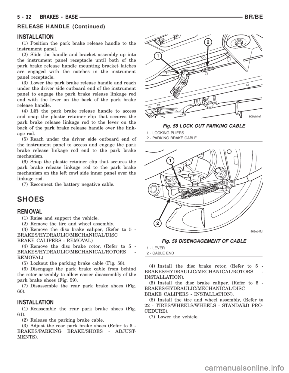
(5) Lockout the parking brake cable (Fig. 58).
(6) Disengage the park brake cable from behind
the rotor assembly to allow easier disassembly of the
park brake shoes (Fig. 59).
(7) Disassemble the rear park brake shoes (Fig.
60).
INSTALLATION
(1) Reassemble the rear park brake shoes (Fig.
61).
(2) Release the parking brake cable.
(3) Adjust the rear park brake shoes (Refer to 5 -
BRAKES/PARKING BRAKE/SHOES - ADJUST-
MENTS).(4) Install the disc brake rotor, (Refer to 5 -
BRAKES/HYDRAULIC/MECHANICAL/ROTORS -
INSTALLATION).
(5) Install the disc brake caliper, (Refer to 5 -
BRAKES/HYDRAULIC/MECHANICAL/DISC
BRAKE CALIPERS - INSTALLATION).
(6) Install the tire and wheel assembly, (Refer to
22 - TIRES/WHEELS/WHEELS - STANDARD PRO-
CEDURE).
(7) Lower the vehicle.
Fig. 58 LOCK OUT PARKING CABLE
1 - LOCKING PLIERS
2 - PARKING BRAKE CABLE
Fig. 59 DISENGAGEMENT OF CABLE
1 - LEVER
2 - CABLE END
5 - 32 BRAKES - BASEBR/BE
RELEASE HANDLE (Continued)
Page 224 of 2255

BRAKES - ABS
TABLE OF CONTENTS
page page
BRAKES - ABS
DESCRIPTION.........................35
OPERATION...........................36
DIAGNOSIS AND TESTING - ANTILOCK
BRAKES............................36
STANDARD PROCEDURE
STANDARD PROCEDURE - RWAL SERVICE
PRECAUTIONS.......................36
STANDARD PROCEDURE - BLEEDING ABS
BRAKE SYSTEM......................36
SPECIFICATIONS
TORQUE CHART......................37
FRONT WHEEL SPEED SENSOR
DESCRIPTION.........................38
OPERATION...........................38
REMOVAL
REMOVAL - 4X2......................39REMOVAL - 4X4......................39
INSTALLATION
INSTALLATION - 4X2...................39
INSTALLATION - 4X4...................39
REAR WHEEL SPEED SENSOR
DIAGNOSIS AND TESTING - REAR WHEEL
SPEED SENSOR......................40
REMOVAL.............................40
INSTALLATION.........................40
HCU (HYDRAULIC CONTROL UNIT)
DESCRIPTION.........................40
OPERATION...........................40
REMOVAL.............................41
INSTALLATION.........................41
BRAKES - ABS
DESCRIPTION
The antilock brake system (ABS) is an electroni-
cally operated, all wheel brake control system. 2500
and 3500 vehicles have Electronic Brake Distribution
(EBD) designed into the systen which eliminates the
combination/proportioning valve.
The system is designed to prevent wheel lockup
and maintain steering control during periods of high
wheel slip when braking. Preventing lockup is accom-
plished by modulating fluid pressure to the wheel
brake units.
The hydraulic system is a three channel design.
The front wheel brakes are controlled individually
and the rear wheel brakes in tandem (Fig. 1). The
ABS electrical system is separate from other electri-
cal circuits in the vehicle. A specially programmed
controller antilock brake unit operates the system
components.
ABS system major components include:
²Controller Antilock Brakes (CAB)
²Hydraulic Control Unit (HCU)
²Wheel Speed Sensors (WSS)²ABS Warning Light
Fig. 1 Antilock Brake System
1 - MASTER CYLINDER AND RESERVOIR
2 - POWER BRAKE BOOSTER
3 - WIRES TO WHEEL SPEED SENSORS
4 - RIGHT REAR WHEEL
5 - LEFT REAR WHEEL
6 - HYDRAULIC BRAKE LINES TO WHEELS
7 - COMBINATION VALVE
8 - HARNESS
9 - RIGHT FRONT WHEEL
10 - LEFT FRONT WHEEL
11 - CAB/HCU
BR/BEBRAKES - ABS 5 - 35
Page 225 of 2255
OPERATION
Battery voltage is supplied to the CAB when a
speed of 15 miles per hour is reached. The CAB per-
forms a system initialization procedure at this point.
Initialization consists of a static and dynamic self
check of system electrical components.
The static and dynamic checks occurs at ignition
start up. During the dynamic check, the CAB briefly
cycles the pump and solenoids to verify operation. An
audible noise may be heard during this self check.
This noise should be considered normal.
If an ABS component exhibits a fault during ini-
tialization, the CAB illuminates the amber warning
light and registers a fault code in the microprocessor
memory.
The CAB monitors wheel speed sensor inputs con-
tinuously while the vehicle is in motion. However,
the CAB will not activate any ABS components as
long as sensor inputs indicate normal braking.
During normal braking, the master cylinder, power
booster and wheel brake units all function as they
would in a vehicle without ABS. The HCU compo-
nents are not activated.
The purpose of the antilock system is to prevent
wheel lockup during periods of high wheel slip. Pre-
venting lockup helps maintain vehicle braking action
and steering control.
The antilock CAB activates the system whenever
sensor signals indicate periods of wheel slip. Periods
of wheel slip occur when brake stops involve high
pedal pressure and rate of vehicle deceleration.
The antilock system prevents lockup during a
wheel slip condition by modulating fluid apply pres-
sure to the wheel brake units.
Brake fluid apply pressure is modulated according
to wheel speed, degree of slip and rate of decelera-
tion. Sensors at each front wheel convert wheel speed
into electrical signals. These signals are transmitted
to the CAB for processing and determination of
wheel slip and deceleration rate.
The ABS system has three fluid pressure control
channels. The front brakes are controlled separately
and the rear brakes in tandem. A speed sensor input
signal indicating a wheel slip condition activates the
CAB antilock program.
There are Two solenoid valves (Isolation and Dump
valve) which are used in each antilock control chan-
nel. The valves are all located within the HCU valve
body and work in pairs to either increase, hold, or
decrease apply pressure as needed in the individual
control channels.
During an ABS stop the ISO valve actuates, Stop-
ping anymore pressure build Ðup to the calipers.
Then the Dump valve dumps off pressure until the
wheel unlocks. This will continue until the wheels
quit slipping altogether.
DIAGNOSIS AND TESTING - ANTILOCK
BRAKES
The ABS brake system performs several self-tests
every time the ignition switch is turned on and the
vehicle is driven. The CAB monitors the systems
input and output circuits to verify the system is oper-
ating correctly. If the on board diagnostic system
senses that a circuit is malfunctioning the system
will set a trouble code in its memory.
NOTE: An audible noise may be heard during the
self-test. This noise should be considered normal.
NOTE: The MDS or DRB III scan tool is used to
diagnose the ABS system. For additional informa-
tion refer to the Antilock Brake section in Group
8W. For test procedures refer to the Chassis Diag-
nostic Manual.
STANDARD PROCEDURE
STANDARD PROCEDURE - RWAL SERVICE
PRECAUTIONS
The RWAL uses an electronic control module, the
CAB. This module is designed to withstand normal
current draws associated with vehicle operation.
Care must be taken to avoid overloading the CAB
circuits.In testing for open or short circuits, do
not ground or apply voltage to any of the cir-
cuits unless instructed to do so for a diagnostic
procedure.These circuits should only be tested
using a high impedance multi-meter or the DRB
tester as described in this section. Power should
never be removed or applied to any control module
with the ignition in the ON position. Before removing
or connecting battery cables, fuses, or connectors,
always turn the ignition to the OFF position.
CAUTION: Use only factory wiring harnesses. Do
not cut or splice wiring to the brake circuits. The
addition of after-market electrical equipment (car
phone, radar detector, citizen band radio, trailer
lighting, trailer brakes, ect.) on a vehicle equipped
with antilock brakes may affect the function of the
antilock brake system.
STANDARD PROCEDURE - BLEEDING ABS
BRAKE SYSTEM
ABS system bleeding requires conventional bleed-
ing methods plus use of the DRB scan tool. The pro-
cedure involves performing a base brake bleeding,
followed by use of the scan tool to cycle and bleed the
5 - 36 BRAKES - ABSBR/BE
BRAKES - ABS (Continued)
Page 226 of 2255
HCU pump and solenoids. A second base brake bleed-
ing procedure is then required to remove any air
remaining in the system.
(1) Perform the base brake bleeding, (Refer to 5 -
BRAKES/HYDRAULIC/MECHANICAL - STAN-
DARD PROCEDURE).
(2) Connect the scan tool to the Data Link Connec-
tor.(3) Select ANTILOCK BRAKES, followed by MIS-
CELLANEOUS, then ABS BRAKES. Follow the
instructions displayed. When scan tool displays TEST
COMPLETE, disconnect scan tool and proceed.
(4) Perform base brake bleeding a second time,
(Refer to 5 - BRAKES/HYDRAULIC/MECHANICAL -
STANDARD PROCEDURE).
(5) Top off master cylinder fluid level and verify
proper brake operation before moving vehicle.
SPECIFICATIONS
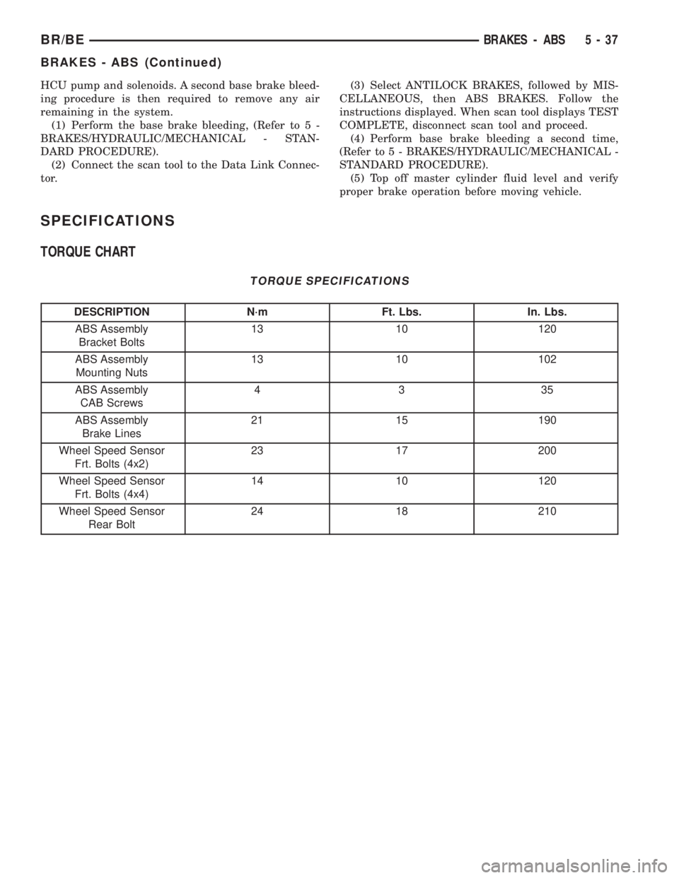
TORQUE CHART
TORQUE SPECIFICATIONS
DESCRIPTION N´m Ft. Lbs. In. Lbs.
ABS Assembly
Bracket Bolts13 10 120
ABS Assembly
Mounting Nuts13 10 102
ABS Assembly
CAB Screws4335
ABS Assembly
Brake Lines21 15 190
Wheel Speed Sensor
Frt. Bolts (4x2)23 17 200
Wheel Speed Sensor
Frt. Bolts (4x4)14 10 120
Wheel Speed Sensor
Rear Bolt24 18 210
BR/BEBRAKES - ABS 5 - 37
BRAKES - ABS (Continued)
Page 227 of 2255
FRONT WHEEL SPEED
SENSOR
DESCRIPTION
The ABS brake system uses 3 wheel speed sensors.
A sensor is mounted to each front steering knuckles.
The third sensor is mounted on top of the rear axle
differential housing.
OPERATION
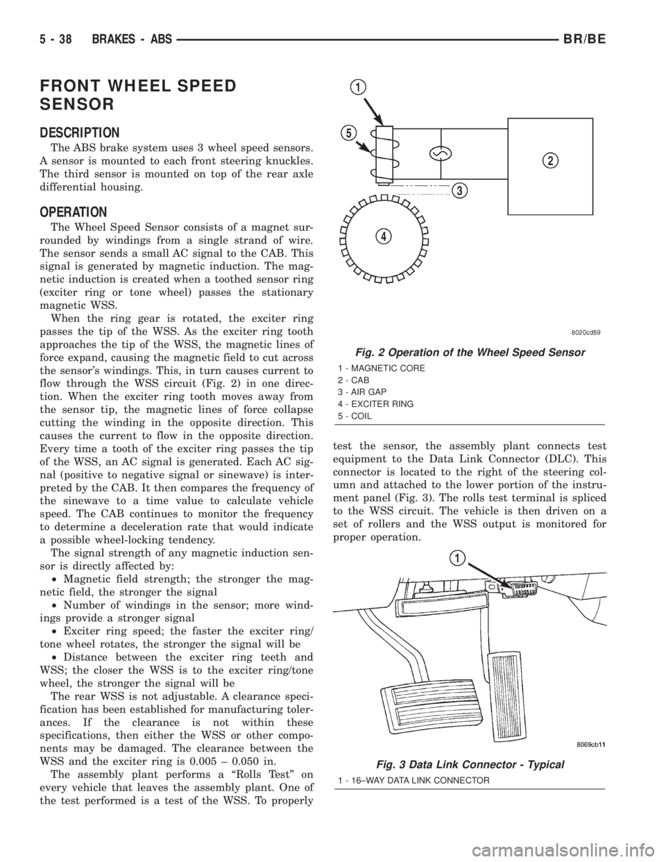
The Wheel Speed Sensor consists of a magnet sur-
rounded by windings from a single strand of wire.
The sensor sends a small AC signal to the CAB. This
signal is generated by magnetic induction. The mag-
netic induction is created when a toothed sensor ring
(exciter ring or tone wheel) passes the stationary
magnetic WSS.
When the ring gear is rotated, the exciter ring
passes the tip of the WSS. As the exciter ring tooth
approaches the tip of the WSS, the magnetic lines of
force expand, causing the magnetic field to cut across
the sensor's windings. This, in turn causes current to
flow through the WSS circuit (Fig. 2) in one direc-
tion. When the exciter ring tooth moves away from
the sensor tip, the magnetic lines of force collapse
cutting the winding in the opposite direction. This
causes the current to flow in the opposite direction.
Every time a tooth of the exciter ring passes the tip
of the WSS, an AC signal is generated. Each AC sig-
nal (positive to negative signal or sinewave) is inter-
preted by the CAB. It then compares the frequency of
the sinewave to a time value to calculate vehicle
speed. The CAB continues to monitor the frequency
to determine a deceleration rate that would indicate
a possible wheel-locking tendency.
The signal strength of any magnetic induction sen-
sor is directly affected by:
²Magnetic field strength; the stronger the mag-
netic field, the stronger the signal
²Number of windings in the sensor; more wind-
ings provide a stronger signal
²Exciter ring speed; the faster the exciter ring/
tone wheel rotates, the stronger the signal will be
²Distance between the exciter ring teeth and
WSS; the closer the WSS is to the exciter ring/tone
wheel, the stronger the signal will be
The rear WSS is not adjustable. A clearance speci-
fication has been established for manufacturing toler-
ances. If the clearance is not within these
specifications, then either the WSS or other compo-
nents may be damaged. The clearance between the
WSS and the exciter ring is 0.005 ± 0.050 in.
The assembly plant performs a ªRolls Testº on
every vehicle that leaves the assembly plant. One of
the test performed is a test of the WSS. To properlytest the sensor, the assembly plant connects test
equipment to the Data Link Connector (DLC). This
connector is located to the right of the steering col-
umn and attached to the lower portion of the instru-
ment panel (Fig. 3). The rolls test terminal is spliced
to the WSS circuit. The vehicle is then driven on a
set of rollers and the WSS output is monitored for
proper operation.
Fig. 2 Operation of the Wheel Speed Sensor
1 - MAGNETIC CORE
2 - CAB
3 - AIR GAP
4 - EXCITER RING
5 - COIL
Fig. 3 Data Link Connector - Typical
1 - 16±WAY DATA LINK CONNECTOR
5 - 38 BRAKES - ABSBR/BE
Page 229 of 2255
NOTE: Check the sensor wire routing. Be sure the
wire is clear of all chassis components and is not
twisted or kinked at any spot.
(6) Install the tire and wheel assembly.
(7) Remove the support and lower the vehicle.
(8) Reconnect the ABS wheel speed sensor wire
electrical connector inside the engine compartment.
(9) Apply the brakes several times to seat the
brake shoes and caliper piston. Do not move the vehi-
cle until a firm brake pedal is obtained.
(10) Verify the wheel speed sensor operation with
a scan tool.
REAR WHEEL SPEED SENSOR
DIAGNOSIS AND TESTING - REAR WHEEL
SPEED SENSOR
Diagnosis of base brake conditions which are
mechanical in nature should be performed first. This
includes brake noise, lack of power assist, parking
brake, or vehicle vibration during normal braking.
The Antilock brake system performs several self-
tests every time the ignition switch is turned on and
the vehicle is driven. The CAB monitors the system
inputs and outputs circuits to verify the system is
operating properly. If the CAB senses a malfunction
in the system it will set a DTC into memory and trig-
ger the warning lamp.
NOTE: The MDS or DRB III scan tool is used to
diagnose the Antilock Brake system. For test proce-
dures refer to the Chassis Diagnostic Manual.
REMOVAL
(1) Raise vehicle on hoist.
(2) Remove brake line mounting nut and remove
the brake line from the sensor stud.
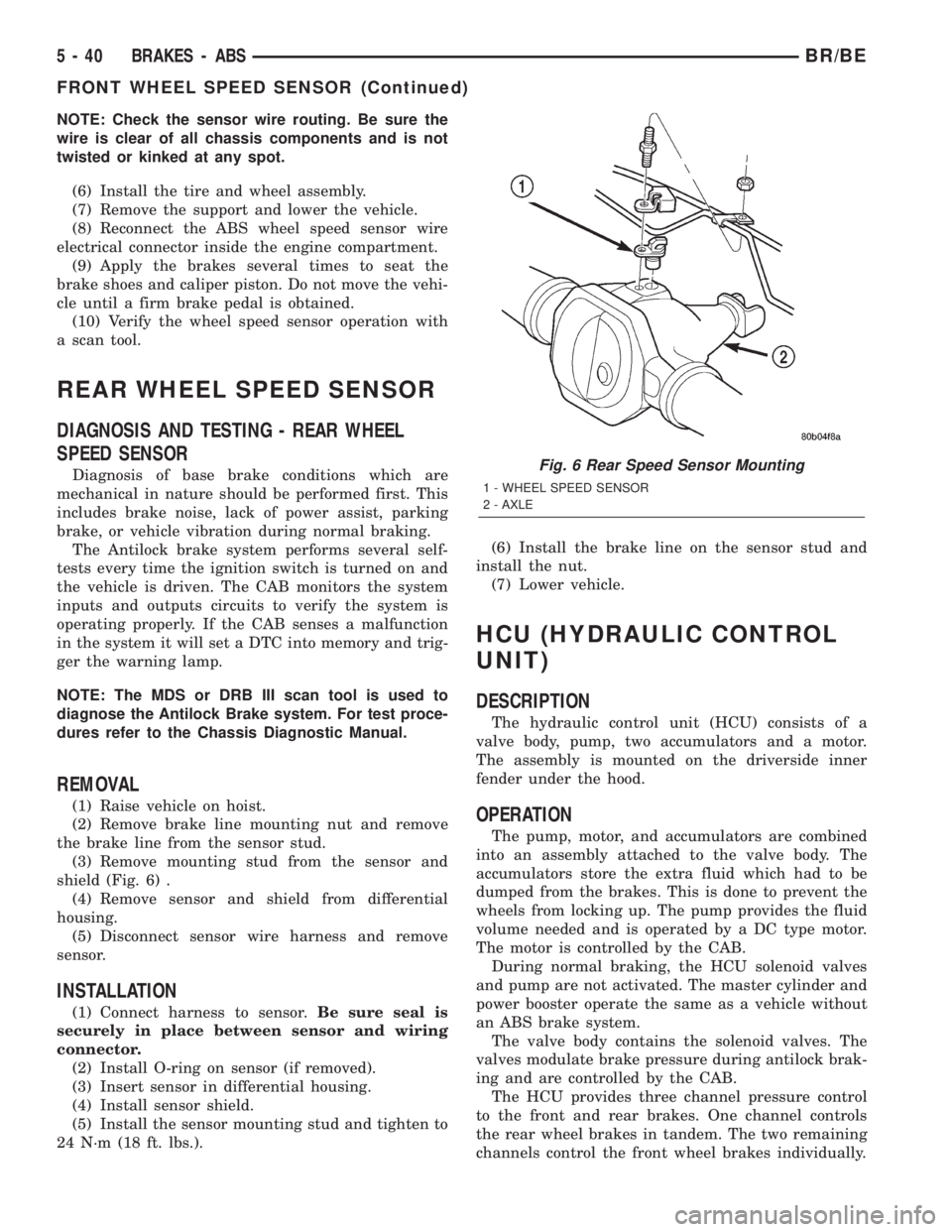
(3) Remove mounting stud from the sensor and
shield (Fig. 6) .
(4) Remove sensor and shield from differential
housing.
(5) Disconnect sensor wire harness and remove
sensor.
INSTALLATION
(1) Connect harness to sensor.Be sure seal is
securely in place between sensor and wiring
connector.
(2) Install O-ring on sensor (if removed).
(3) Insert sensor in differential housing.
(4) Install sensor shield.
(5) Install the sensor mounting stud and tighten to
24 N´m (18 ft. lbs.).(6) Install the brake line on the sensor stud and
install the nut.
(7) Lower vehicle.
HCU (HYDRAULIC CONTROL
UNIT)
DESCRIPTION
The hydraulic control unit (HCU) consists of a
valve body, pump, two accumulators and a motor.
The assembly is mounted on the driverside inner
fender under the hood.
OPERATION
The pump, motor, and accumulators are combined
into an assembly attached to the valve body. The
accumulators store the extra fluid which had to be
dumped from the brakes. This is done to prevent the
wheels from locking up. The pump provides the fluid
volume needed and is operated by a DC type motor.
The motor is controlled by the CAB.
During normal braking, the HCU solenoid valves
and pump are not activated. The master cylinder and
power booster operate the same as a vehicle without
an ABS brake system.
The valve body contains the solenoid valves. The
valves modulate brake pressure during antilock brak-
ing and are controlled by the CAB.
The HCU provides three channel pressure control
to the front and rear brakes. One channel controls
the rear wheel brakes in tandem. The two remaining
channels control the front wheel brakes individually.
Fig. 6 Rear Speed Sensor Mounting
1 - WHEEL SPEED SENSOR
2 - AXLE
5 - 40 BRAKES - ABSBR/BE
FRONT WHEEL SPEED SENSOR (Continued)